Wideband Meta-dielectric Resonator Antenna
Wenke Jiang, Guanghui Xu, Yanbin Luo, Zhixiang Huang, Wei Wang,
Mouping Jin, and Hong-Li Peng
1Information Materials and Intelligent Sensing Laboratory of Anhui Province
Anhui University, Hefei 230039, China
1036697676@qq.com, ghxu86@ahu.edu.cn, zxhuang@ahu.edu.cn
2East China Research Institute of Electronic Engineering
Hefei 230088, China
luoyanb001@163.com, shu00ww@163.com, jinmoup_cn@sina.com
3Key Laboratory of Ministry of Education for Design and Electromagnetic Compatibility of
High-Speed Electronics Systems
Shanghai Jiao Tong University, Shanghai 200240, China
hl.peng@sjtu.edu.cn
Submitted On: December 12, 2024; Accepted On: April 29, 2025
ABSTRACT
A novel wideband meta-dielectric resonator antenna (MDRA) is presented in this paper. Metamaterial technology is introduced to broaden the impedance bandwidth of the DRA. The proposed MDRA comprises a 44 array of subwavelength meta-dielectric resonator cuboids (0.09600.09600.1160, where 0 denotes the free space wavelength at the center frequency) fed by a microstrip-slot configuration. The proposed MDRA achieves a wideband -10 dB impedance bandwidth of 36% (1.88-2.71 GHz) with a stable radiation pattern. Due to its advantages of low profile, simple structure, wide bandwidth and stable radiation pattern, the MDRA may be applied to the wideband wireless communication systems.
Index Terms: Dielectric resonator antenna, metamaterial, stable radiation pattern, wideband.
I. INTRODUCTION
With the development of 5G and B5G wireless communications, data transmission capacity is in increasing demand [1]. Meanwhile, wideband antennas, as important transmitting and receiving devices, have attracted considerable attention for enhancing communication capacity. To date, many different types of antennas have been developed for broadband operation, such as L-probe fed antenna [2], E-shaped patch antenna [3], magneto-electric dipoles [4] and others [5]. In addition, dielectric resonator antennas (DRAs) are also adopted for wideband applications due to their light weight, cost efficiency, smaller size and high radiation efficiency.
To achieve wideband operation of DRAs, many techniques have been proposed and developed. One technique is to adopt special DRA structures to excite multiple modes for bandwidth enhancement, such as H- or T-shaped DRAs [6-9], but their radiation patterns do not exhibit stable broadside characteristics. For example, a diversity cylindrical DRA can achieve a wider impedance bandwidth of 30%, covering 3.08-4.16 GHz, but its broadside radiation pattern is degraded [9].
An alternative approach for bandwidth enhancement is to excite hybrid resonant modes in the DRA using a complex feeding network [10-12]; however, this method is limited by the intricate feed structure and increased antenna dimensions. In [10], a tri-mode stub-loaded resonator was employed as the feeding network to achieve an impedance bandwidth of 34%. In [11], a cup-like DRA with a coil feeding structure demonstrated a bandwidth of 29%. In [12], a 1-to-4 slot-coupled feeding mechanism was utilized to excite a cylindrical DRA, achieving an impedance bandwidth of 25.2% (without aperture mode) and 34% (with aperture mode). In addition, fractal geometries and multi-element configurations have been employed to significantly enhance the bandwidth of DRAs [13-17], but these designs typically exhibit asymmetric radiation patterns and high cross-polarization levels. In [18], a wideband DRA with a lattice structure was proposed, but it requires a high-permittivity (about 40) lattice body and an additional SIW cavity.
Recently, metamaterials have received a lot of attention due to their unique electromagnetic physics perspectives [19-21]. However, to date, few studies have focused on metamaterial-based DRAs. In [20], a DRA integrated with a top-loaded rotatable anisotropic metasurface was proposed, achieving an impedance bandwidth of 0.65 GHz (6.52-7.17 GHz). In [21], by adding a 66 array of periodic metallic patch cells and shorting walls, the impedance bandwidth of the DRA is dramatically increased to about 17.2% (1.75-2.08 GHz), and it achieves a stable gain of 6.6 dBi and a lower cross-polarization level. However, its bandwidth is still narrow, and the rectangular structure of the DRA is not completely changed (extra metasurface patches are added).
In this work, metamaterial technology is adopted to enhance the impedance bandwidth of the DRA while maintaining good radiation patterns. A novel wideband meta-dielectric resonator antenna (MDRA) is proposed in this paper. The MDRA consists of a 44 meta-dielectric resonator cuboid array fed by a microstrip-slot configuration. Each cuboid element has a length of 12 mm, which is about 0.0960 (where 0 denotes the free-space wavelength at the center frequency). Its 15 mm height corresponds to 0.1160. Therefore, the element size meets the subwavelength characteristic of metamaterials. Through the antenna fabrication and testing, the proposed MDRA achieves a 36% -10 dB impedance bandwidth (1.88-2.71 GHz) with a stable radiation pattern. Due to these advantages, including low profile, simple structure, wide bandwidth and stable radiation characteristics, the MDRA is highly suitable for modern wireless communication systems with stringent miniaturization requirements, such as 5G mobile terminals and IoT devices.
This paper is organized as follows. Section II presents the operation principle and design of the MDRA. Section III compares and discusses the simulated and measured results. Section IV draws the final conclusions.
II. THEORETICAL ANALYSIS OF THE MDRA
A. Configuration of the MDRA
Figure shows the top and side configurations of the MDRA on the grounded substrate with a thickness of t. The RT/duroid 5880 with a dielectric constant of 2.2 and loss tangent of 0.0009 is adopted as the substrate. The proposed MDRA consists of a 44 meta-dielectric resonator array composed of AlO material cuboids with a length of d, width of d and height of h. Parameters s and s are the gaps between cuboid elements, as shown in Fig. 1 (a). The slot with a length of l and width of w provides electromagnetic coupling to the meta-dielectric resonator and a microstrip line is employed for thefeeding.
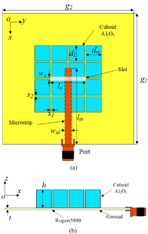
Figure 1: Configuration of the wideband meta-dielectric resonator antenna: (a) top view and (b) side view.
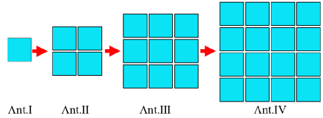
Figure 2: Structural evolution of the wideband MDRA.
B. Design of the proposed MDRA
Figure 2 shows the design flow of the proposed MDRA. Ant.I has one meta-dielectric element. The 22 meta-dielectric array is defined as Ant.II. Ant.III comprises the 33 meta-dielectric array. Finally, Ant.IV consists of the 44 meta-dielectric array. Their simulated |S11| is shown in Fig. 3. It is noted that the resonant frequency decreases from Ant.I to Ant.IV. This is because the dielectric structure size gradually increases.
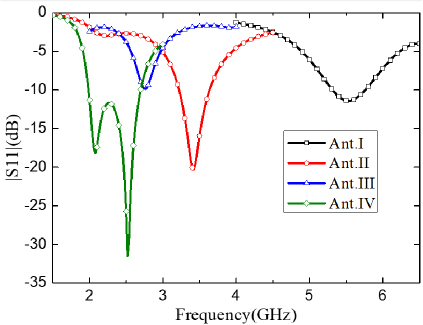
Figure 3: Simulated |S11| of the four evolution antennas.
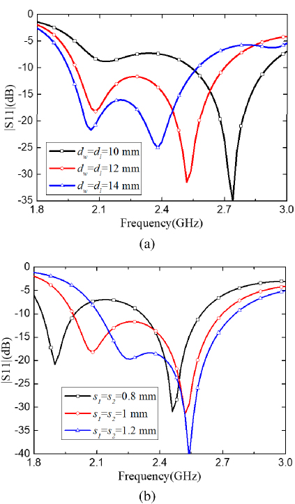
Figure 4: Simulated |S11| of the proposed MDRA with sizes d, d, s and s.
According to Ant.IV, structural size optimization is performed. By fixing the gap width (ss1 mm), the side length d of the meta-dielectric cuboid is decreased from 14 to 10 mm, and the impedance bandwidths of the proposed MDRA change, as shown in Fig. 4 (a). When the gap width (s and s) between the meta-dielectric cuboids changes, the simulated |S11| is displayed in Fig. 4 (b). When dd12 mm and ss1 mm, a wider impedance bandwidth is achieved and two resonant frequency points (2.08 and 2.54 GHz) are obtained for enhancing the impedance bandwidth. The final geometrical parameters of the proposed MDRA are summarized in Table 1.
Table 1: Key parameters of MDRA (Unit: mm)
| g | g | d | d | l | w |
| 10 | 10 | 12 | 12 | 27 | 2 |
| s | s | l | w | h | t |
| 1 | 1 | 58 | 4.85 | 15 | 1.57 |
C. Work principle of the proposed MDRA
To explore the working principle of MDRA, the electric field distributions at the two resonant frequency points are simulated and analyzed. First, the four side view planes (1#, 2#, 3# and 4#) of MDRA in the E-plane direction are selected to investigate the electric field, as shown in Fig. 5. In addition, the electric field of the MDRA from the top view is also a key observation surface and is provided for studying the radiation performances.
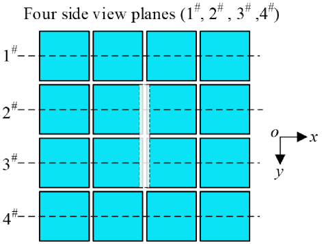
Figure 5: Four side view planes (1#, 2#, 3# and 4#) of MDRA in the E-plane direction.
Figure 6 shows the simulated electric field distributions of MDRA at 2.08 GHz. The antenna operates in TE111 mode, with low-loss characteristics and uniform field distribution for efficient energy radiation. In the top view shown in Fig. 6 (a), the electric field in the middle part is stronger and those on both sides are weaker, but the electric field directions on the top surface of each meta-dielectric cuboid are almost the same. In the side view shown in Fig. 6 (b), the electric fields of each horizontal row cuboid have the same rotation direction. Therefore, the corresponding far-field radiation is good, as shown in Fig. 8.
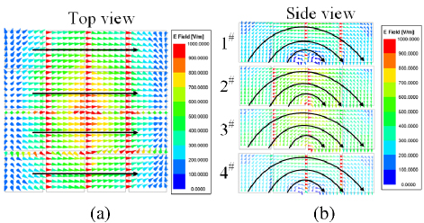
Figure 6: Simulated electric field distributions of MDRA at resonant frequency of 2.08 GHz: (a) top view and (b) side view.
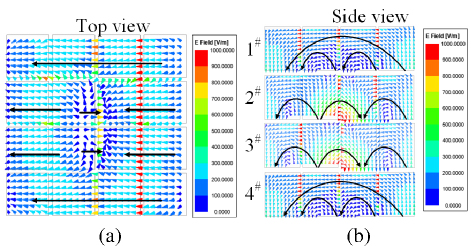
Figure 7: Simulated electric field distributions of MDRA at resonant frequency of 2.54 GHz: (a) top view and (b) side view.
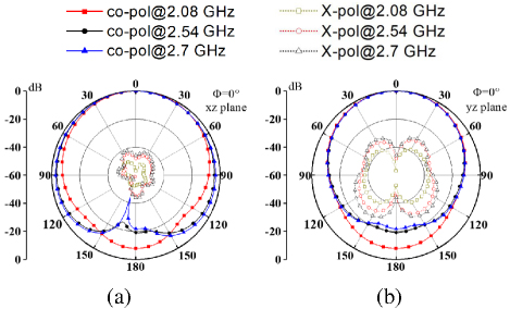
Figure 8: Simulated normalized radiation patterns of proposed MDRA at frequencies of 2.08, 2.54 and 2.7 GHz: (a) in the E-plane and (b) in the H-plane.
Similarly, Figs. 7 (a) and (b) display MDRA’s electric field distributions at 2.54 GHz in top and side views. The antenna’s center operates in TE131 mode, where its multi-lobe field strengthens radiation coupling and boosts performance. Top view and side view show weaker electric fields in the middle and side regions but stronger fields at vertical gaps, while maintaining consistent field directions across all cuboids. The corresponding far-field radiation is good, as shown in Fig. 8. In addition, it is found that the main beams with different frequencies are similar and the antenna has a lower cross-polarization level in the E-plane (40 dB) and H-plane (30 dB).
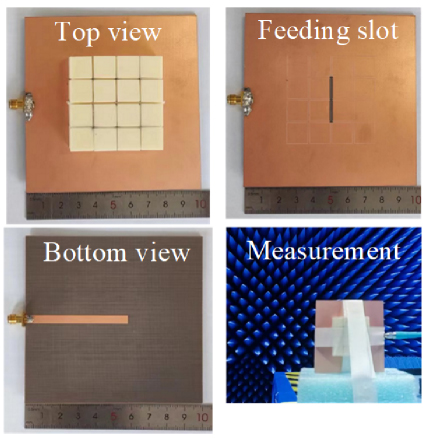
Figure 9: Fabrication and measurement photos of MDRA.
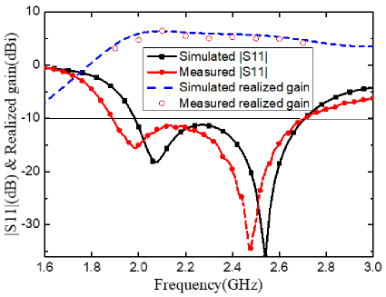
Figure 10: Simulated and measured |S11| and gains of MDRA.
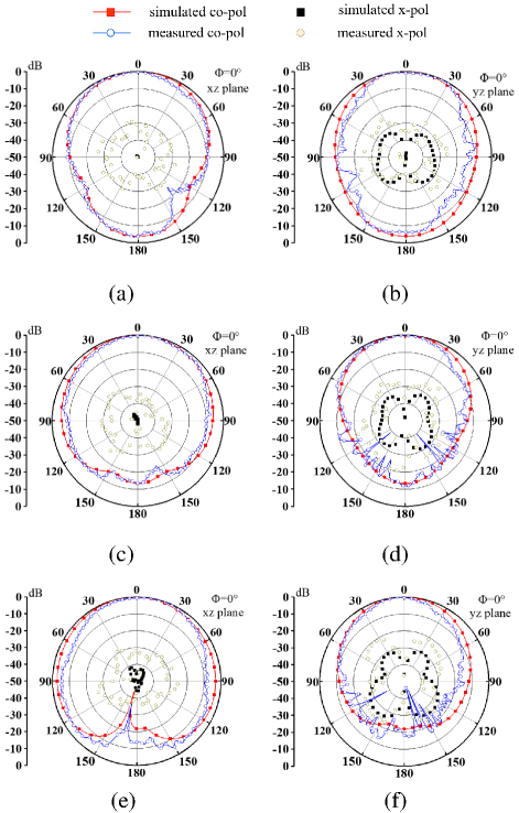
Figure 11: Simulated and measured normalized radiation patterns of the antenna: (a) 1.9 GHz in the E-plane, (b) 1.9 GHz in the H-plane, (c) 2.3 GHz in the E-plane, (d) 2.3 GHz in the H-plane, (e) 2.7 GHz in the E-plane, and (f) 2.7 GHz in the H-plane.
Table 2: Comparison of proposed MDRA and previous wideband DRAs
| Ref. | Type of Structure | BW (%) | f (GHz) | Size (0) | Peak Gain (dBi) | Complexity | Radiation Pattern | |
| [7] | Asymmetrical T-shaped with trapezoidal probe feeding | 75.08 | 6.1 | 9.8 | 0.140.480.26 | 7.35 | Medium | Unstable broadside |
| [8] | Triangular DRA | 47.4 | 5.68 | 10 | 0.0960.350.35 | 6.5 | Simple | Unstable broadside |
| [10] | Rectangular DRA | 34 | 2.6 | 10.2 | 2.272.271.45 | 9.1 | Complex | Unstable broadside |
| [11] | Cup-shaped DRA | 29 | 3.5 | 4.3 | 0.250.250.23 | Medium | Stable | |
| [16] | 22 Cylindrical DRA array | 13.7 | 8 | 12 | 1.891.890.24 | 17.8 | Simple | Unstable broadside |
| [20] | DRA with a top-loaded rotatable anisotropic metasurface | 9.5 | 6.8 | 20.5 | 0.880.630.072 | 5.57 | Complex | Stable |
| [21] | DRA with metasurface patches and shorting walls | 17.2 | 1.9 | 15 | 0.320.320.044 | 6.6 | Complex | Stable |
| This Work | 44 meta-dielectric resonator | 36 | 2.33 | 9.8 | 0.40.40.116 | 7.69 | Simple | Stable |
0 denotes free space wavelength at center frequency
III. EXPERIMENTAL RESULTS AND DISCUSSION
The results comparison between simulations and measurements of the proposed MDRA are performed in this section. Fabrication and measurement photos of the MDRA are given in Fig. 9. Simulated and measured |S11| and gains of the MDRA are compared in Fig. 10. Simulated and measured -10 dB impedance bandwidths of the proposed MDRA are about 30% (2-2.7 GHz) and 36% (1.88-2.71 GHz), respectively. Measured |S11| and gains have a frequency deviation with the simulated ones due to changes in dielectric constant and fabrication assembly errors. The simulated and measured radiation patterns of MDRA at frequencies of 1.9, 2.3 and 2.7 GHz are compared in Fig. 11. Simulated and measured main lobes are similar and they have stable radiation pattern characteristics. Cross-polarization levels are less than 30 dB in the main lobe, but measured ones are less than 20 dB. The difference in cross-polarization level may be caused by errors in fabrication, assembly and radiation measurement. These differences indicate acceptable agreement.
Table 2 summarizes the comparison results of the proposed MDRA and other existing wideband DRAs. It is noted that the proposed MDRA features the advantages of low profile, simple structure, wide bandwidth and stable radiation pattern. Due to the symmetrical structure, the proposed MDRA has a lower cross-polarization level at the operating band. The design achieves broadband performance through coupling effects between subwavelength DRA arrays, offering a novel approach to address bandwidth limitations. Furthermore, while [20, 21] implemented metasurface properties by adding metal patches on the resonator surface, the proposed method directly realizes wideband functionality through the inherent material properties and periodic arrangement of dielectric resonators.
IV. CONCLUSION
In this paper, a novel wideband MDRA is presented based on metamaterial technology. By constructing a subwavelength resonant unit array, the bandwidth limitations of conventional DRAs have been successfully overcome. The MDRA employs a 44 periodically arranged dielectric resonator array, which is fed by a microstrip-slot configuration. Experimental verification demonstrates that the proposed MDRA achieves a wideband -10 dB impedance bandwidth of 36% (1.88-2.71 GHz) with a peak gain of 7.69 dBi and a stable radiation pattern. Compared with existing dielectric resonator antennas, the proposed MDRA utilizes a subwavelength resonator unit array, exhibiting advantages of low profile, simple structure, wide bandwidth and stable radiation performance. These characteristics make it particularly suitable for application scenarios with stringent requirements on antenna integration and radiation performance, including 5G mobile terminals and IoT devices.
REFERENCES
[1] W. Hong, Z. H. Jiang, C. Yu, P. Chen, Z. Yu, H. Zhang, B. Yang, X. Pang, M. Jiang, Y. Cheng, M. K. Taher Al-Nuaimi, Y. Zhang, J. Chen, and S. He, “Multibeam antenna technologies for 5G wireless communications,” IEEE Trans. Antennas Propag, vol. 65, no. 12, pp. 6231-6249, Dec. 2017.
[2] L. Wang, Y.-X. Guo, and W.-X. Sheng, “Wideband high-gain 60-GHz LTCC L-probe patch antenna array with a soft surface,” IEEE Trans. Antennas Propag., vol. 61, no. 4, pp. 1802-1809, Apr. 2013.
[3] K. Fan, Z.-C. Hao, and Q. Yuan, “A low-profile wideband substrate integrated waveguide cavity-backed E-shaped patch antenna for the QLINKPAN applications,” IEEE Trans. Antennas Propag., vol. 65, no. 11, pp. 5667-5676, Nov. 2017.
[4] J. Sun, A. Li, and K.-M. Luk, “A high-gain millimeter-wave magneto-electric dipole array with packaged microstrip line feed network,” IEEE Antennas Wireless Propag. Lett., vol. 19, no. 10, pp. 1669-1673, Oct. 2020.
[5] J. Yin, Q. Wu, C. Yu, H. Wang, and W. Hong, “Broadband symmetrical E-shaped patch antenna with multimode resonance for 5G millimeter wave applications,” IEEE Trans. Antennas Propag., vol. 67, no. 7, pp. 4474-4483, July 2019.
[6] X. Liang and T. A. Denidni, “H-shaped dielectric resonator antenna for wideband applications,” IEEE Antennas Wireless Propag. Lett., vol. 7, pp. 163-166, 2008.
[7] Y. Gao, Z. Feng, and L. Zhang, “Compact asymmetrical T-shaped dielectric resonator antenna for broadband applications,” IEEE Trans. Antennas Propag., vol. 60, no. 3, pp. 1611-1615, Mar. 2012.
[8] S. Maity and B. Gupta, “Experimental investigations on wideband triangular dielectric resonator antenna,” IEEE Trans. Antennas Propag., vol. 64, no. 12, pp. 5483-5486, Dec. 2016.
[9] T. Yang, J. Ren, B. Zhang, Y.-T. Liu, T. Ma, and Y. Yin, “Wideband diversity cylindrical dielectric resonator antenna based on multimode resonance,” IEEE Antennas Wireless Propag. Lett., vol. 22, no. 9, pp. 2205-2209, Sep. 2023.
[10] H. Liu, H. Tian, L. Liu, and L. Feng, “Co-design of wideband filtering dielectric resonator antenna with high gain,” IEEE Trans. Circuits Syst. II Exp. Briefs, vol. 69, no. 3, pp. 1064-1068, Mar.2022.
[11] S. Zheng, Z.-Y. Zhang, X. Chen, and A. A. Kishk, “Wideband monopole-like cup dielectric resonator antenna with coil feeding structure,” IEEE Trans. Antennas Propag., vol. 70, no. 8, pp. 7118-7123, Aug. 2022.
[12] X. S. Fang, L. P. Weng, and Z. Fan, “Design of the wideband and low-height omnidirectional cylindrical dielectric resonator antenna using arced-apertures feeding,” IEEE Access, vol. 11, pp. 20128-20135, 2023.
[13] A. Gaonkar, M. Ayyappan, and P. Patel, “A novel fractal RDRA for C-band applications,” IEEE Trans. Compon., Packag., Manuf. Technol., vol. 13, no. 7, pp. 995-1002, July 2023.
[14] W. Luo, Y. Feng, Y. Ren, and B. Yin, “A novel wideband fractal rectangular dielectric resonator antenna with improved radiation performance,” AEU-Int. J. Electron. Commun., vol. 142, pp. 153-184, Dec. 2021.
[15] S. Dhar, R. Ghatak, B. Gupta, and D. R. Poddar, “A wideband Minkowski fractal dielectric resonator antenna,” IEEE Trans. Antennas Propag., vol. 61, no. 6, pp. 2895-2903, June 2013.
[16] Q. Wu, H. Li, S.-W. Wong, Z. Zhang, and Y. He, “A simple cylindrical dielectric resonator antenna based on high-order mode with stable high gain,” IEEE Antennas Wireless Propag. Lett., vol. 23, no. 11, pp. 3476-3480, Nov. 2024.
[17] M. K. Saleem, M. A. S. Alkanhal, and A. F. Sheta, “Two element dielectric resonator antenna with beam switching,” Applied Computational Electromagnetics Society (ACES) Journal, vol. 30, no. 11, pp. 1209-1214, Aug. 2021.
[18] X.-Y. Dong, W.-W. Yang, H. Tang, and J.-X. Chen, “Wideband low profile dielectric resonator antenna with a lattice structure,” Electron. Lett., vol. 53, no. 19, pp. 1289-1290, Sep. 2017.
[19] M. Martinis, L. Bernard, K. Mahdjoubi, R. Sauleau, and S. Collardey, “Wideband antenna in cavity based on metasurfaces,” IEEE Antennas Wireless Propag. Lett., vol. 15, pp. 1053-1056, 2016.
[20] X. Shi, C.-W. Shen, Y.-H. Ke, and J.-X. Chen, “A frequency-tunable dielectric resonator antenna with rotatable anisotropic metasurface,” IEEE Antennas Wireless Propag. Lett., vol. 23, no. 1, pp. 429-433, Jan. 2024.
[21] S.-K. Zhao, N.-W. Liu, Q. Chen, G. Fu, and X.-P. Chen, “A low-profile dielectric resonator antenna with compact-size and wide bandwidth by using metasurface,” IEEE Access, vol. 9, pp. 29819-29826, 2021.
BIOGRAPHIES

Wenke Jiang was born in 1998. He received his B.S. degree from Henan Polytechnic University, Jiaozuo, China, in 2022. He is currently pursuing his M.S. degree at Anhui University. His current research interests include dielectric resonator antenna and millimeter-wave antenna.

Guanghui Xu was born in 1986. He received the B.E. degree from Anhui Jianzhu University, Hefei, China, in 2009, the M.E. degree from Shenzhen University, Shenzhen, China, in 2012, and the Ph.D. degree from the Department of Electronic Engineering, Shanghai Jiao Tong University, Shanghai, China, in 2019. His research interests include millimeter-wave (mm-wave) antenna and reconfigurable antennas.

Yanbin Luo received the B.S. degree from the China University of Mining and Technology, Xuzhou, China, in 2015. He is currently pursuing the Ph.D. degree with the Beijing University of Posts and Telecommunications, Beijing, China. His research interests include graphene/GaAs nanowire photodetectors, graphene reconfigurable antennas, wideband antennas and miniaturized antennas.

Zhixiang Huang was born in 1979. He received the B.S. and Ph.D. degrees from Anhui University, Hefei, China, in 2002 and 2007, respectively. His research interests include theoretical and computational research in electromagnetics and imaging, focusing on multiphysics and interdisciplinary research, and fundamental and applied aspects in metamaterials and activemetamaterials.

Wei Wang received the Ph.D. degree in navigation, guidance, and control from Harbin Engineering University (HEU), Harbin, China, in 2005. He was a Post-Doctoral Research Associate at Harbin Institute of Technology, Harbin, from July 2006 to April 2009. His current research interests include location, mapping, and image processing.

Mouping Jin received the Ph.D. degree in electromagnetic field and microwave technology from Xidian University, Xi’an, China, in 2000. His current research interests include antenna systems and microwave passive devices.

Hong-Li Peng was born in Shangluo, China, in 1966. He received the B.S., M.S., and Ph.D. degrees from Xidian University, Xi’an, China, in 1988, 1991, and 2005, respectively. His current research interests mainly include tunable RF and microwave passive circuits research, reconfigurable compact antennas/array analysis and design, and spatial wireless channel modeling.
ACES JOURNAL, Vol. 40, No. 5, 436–442
doi: 10.13052/2025.ACES.J.400507
© 2025 River Publishers