Multi-objective Optimization Design of a DSSRM with U-type Modular Segmental-stator Structure
Xing Wang, Hao Chen, Fengyuan Yu, Wenju Yan, Jianfei Pan, and Yassen Gorbounov
1International Joint Research Center of Central and Eastern European Countries
on New Energy Electric Vehicle Technology and Equipment
Xuzhou 221008, China
3512@cumt.edu.cn, hchen@cumt.edu.cn
2International Cooperation Joint Laboratory of New Energy Power Generation
and Electric Vehicles of Jiangsu Province Colleges and Universities
Xuzhou 221008, China
3Jiangsu Province Foreign Expert Workshop
on New Energy Power Generation and Electric Transportation
Xuzhou 221008, China
4School of Electrical Engineering
China University of Mining and Technology, Xuzhou 221116, China
cumt_yfy@163.com, yanwenju09@126.com
5Shenzhen Research Institute
China University of Mining and Technology, Shenzhen 518057, China
6School of Electromechanical and Control Engineering
Shenzhen University, Shenzhen 518054, China
pjf@szu.edu.cn
7Department of Informatics
New Bulgarian University, Sofia 1618, Bulgaria
y.gorbounov@mgu.bg
Submitted On: December 19, 2024; Accepted On: May 29, 2025
ABSTRACT
A U-type modular double stator switched reluctance motor (DSSRM) which has the merit of high-power density is optimized in this paper. Taking average torque, torque smoothing coefficient and efficiency as objectives, sensitivity analysis on DSSRM is investigated and discussed to select significant geometric variables. On the basis of the initial structural parameters, the multi-objective optimization design is processed by adopting a fuzzy iteration optimization algorithm with weight determination. After the determination of decision result of each structure parameter, the best dimension scheme of the DSSRM is concluded. Moreover, the final scheme proves to perform better than the initial scheme by finite element (FE) analysis. Finally, a prototype motor is manufactured and the experimental results validate the improvement of the DSSRM performance.
Index Terms: Double stator structure, multi-objective optimization, switched reluctance motor, U-type modular structure.
I. INTRODUCTION
The switched reluctance motor (SRM) and its control system, after decades of development, is firmly established. Its inherent merits such as simple, sturdy, durable structure and high reliability contributes to its excellent running performance and high performance/cost ratio.
However, several problems like electromagnetic torque characteristic and large torque ripple still prevent the SRM from becoming a mainstream motor. Thus, many newly designed SRMs are proposed to enhance torque performance and efficiency or to reduce torque ripple, such as double stator switched reluctance motor (DSSRM) [1–6], segmented-rotor SRM [7] and segmented-stator SRM [8–9]. Researchers from the University of Texas at Arlington in the USA presented a concentric DSSRM structure and analyzed its principle and electromagnetic force [1]. The DSSRM structure has a higher torque density because of its larger available winding area than a conventional SRM.
The comprehensive performance of a DSSRM, including design methods [2], mechanical vibration characteristic [3], thermal modeling [4] and rotor shape investigation [5] have been explored and discussed. A 100 kw DSSRM prototype was manufactured to verify that it has the same performance as the permanent magnet motor and, furthermore, has advantages in cost performance [6]. In addition, some scholars have studied the segmental SRM structure [7–9]. The core mass and magnetic flux leakage of a segmental structure are reduced without the connection of a yoke part, thereby improving the efficiency and torque density of the motor. Researchers found that the combination of these structures can further improve the performance of an SRM.
A novel segmented-rotor modular 12/14 DSSRM is presented in [10]. Torque output capability is improved and torque ripple is reduced compared to a conventional 12/8 nonsegmented-rotor DSSRM. Researchers from China University of Mining and Technology presented a novel SRM topology combining U-type modular stator and double stator structure. The decoupling characteristics of the inner and outer motors were verified and the winding configuration scheme was analyzed and discussed in [11].
Besides devising novel structures, conducting optimization design can also improve the performance of the motor [12–22]. In [12], a comprehensive framework for multi-objective design optimization of SRM was proposed to synchronously achieve five key objectives for low-speed electric vehicles application. Paolo Di Barba from University of Pavia in Italy has done a lot of research on benchmark TEAM multi-objective Pareto optimization [13–14]. The particular shape of the Pareto front was established and the design space was thoroughly searched on the basis of considering field uniformity and sensitivity [13]. The TEAM benchmark of magnetic devices under AC conditions was studied and the model for evaluating the quality of the magnetic field produced by distributed windings was proposed and verified [14].
To shorten computational time in multi-objective optimization problems, researchers from McGill University in Canada stated that applying sensitivity analysis is a useful tool to reduce the number of variables, while conflict analysis can reduce the number of objectives [15]. Both sensitivity analysis and conflict analysis were incorporated into the proposed strategy to optimize a fractional slot concentrated winding machine in [16]. In [17], employing finite element (FE) sensitivity analysis, seven initial design variables were reduced to four important variables in the optimization process of a double-sided linear permanent magnet motor. Moreover, sensitivity analysis was also employed to eliminate relatively insignificant geometric variables of SRM optimization problem [18–21]. Amoros and Andrada [18] presented a sensitivity analysis method of the influence to structural parameters on the average electromagnetic force of a double-sided linear SRM. The comprehensive sensitivity analysis was verified to be an effective method for optimizing the linear SRM. In [19], the average torque, average torque per copper loss, and average torque per lamination volume were selected to be optimized objectives, while the stator and rotor pole angles are chosen as the optimization variables, thus a four-phase outer-rotor SRM for electric vehicles was optimized. In [22], a combined weighting method based on the fuzzy optimization iteration was proposed and employed to optimize a single-phase tubular linear SRM.
The main contributions are as follows: (a) investigating the influence of the geometric parameters on the performance of DSSRM in detail by applying sensitivity analysis. Since the modular segmental-stator DSSRM structure has more geometric size parameters than the conventional SRM topology, the sensitivity indices of design variables are more essential to be calculated and analyzed; (b) optimizing the structural parameters to reduce torque ripple and further improve electromagnetic torque performance of the DSSRM by employing a fuzzy iteration optimization algorithm with weight determination.
This paper is organized as follows. The DSSRM structure is introduced in section II and sensitivity analysis is done in section III. Multi-objective optimization is conducted by applying a weight determination iteration algorithm in section IV. The optimal scheme is verified by experiment in section V.
II. STRUCTURE OF DSSRM
The structure of 16/18/18/16 U-type modular DSSRM is shown in Fig. 1. It can be seen that the proposed DSSRM is composed of segmental outer stator, rotor and segmental inner stator. The number of U-shaped outer stator segment, rotor outer salient pole, rotor inner salient pole and U-shaped inner stator segment is 8, 18, 18, 8, respectively.
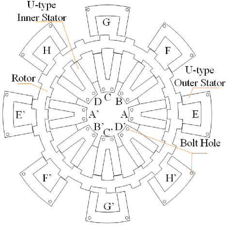
Figure 1: Structure and winding distribution of DSSRM.
Based on general design experience and parameter selection principle, the initial dimension parameter values of DSSRM are selected and presented in Table 1. It should be noted that the center lines of the rotor inner and outer teeth are staggered at a certain mechanical angle to reduce the torque ripple of the motor and the staggered mechanical angle is defined as . According to Table 1, the FE model of DSSRM is established in FLUX software and the performance is analyzed. Figure 2 illustrates the FE model and magnetic field distribution of the DSSRM. When a 12.5 A current is applied to A-phase winding of inner stator and G-phase winding of outer stator simultaneously, Fig. 2 (c) gives the flux density distribution at outer stator aligned position, and Fig. 2 (d) shows it at inner stator aligned position.
Table 1: Initial geometry size of DSSRM
| Item | Variable | Value |
| Outer diameter of outer stator | Dso | 220 mm |
| Outer stator yoke height | bsyo | 9 mm |
| Outer stator pole angle | so | 7.5∘ |
| Outer air gap length | go | 0.3 mm |
| Rotor outer diameter | Dro | 175 mm |
| Rotor outer pole angle | ro | 7.5∘ |
| Rotor inner pole angle | ri | 7.5∘ |
| Rotor outer pole length | hro | 7 mm |
| Rotor inner pole length | hri | 7.2 mm |
| Rotor yoke height | bry | 10 mm |
| Rotor inner diameter | Dri | 127.2 mm |
| Inner air gap length | gi | 0.3 mm |
| Inner stator yoke height | bsyi | 7 mm |
| Inner stator pole angle | si | 7.5∘ |
| Staggered mechanical angle of the rotor inner and outer teeth | 2.5∘ | |
| Outer stator winding turns | No | 88 |
| Inner stator winding turns | Ni | 68 |
| Shaft radius | Dsh | 45 mm |
| Lamination thickness | L | 70 mm |
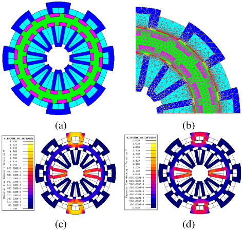
Figure 2: FE model and magnetic field distribution of DSSRM: (a) FE model, (b) mesh map, (c) flux density distribution at outer stator aligned position, and (d) flux density distribution at inner stator aligned position.
For the modular segmental-stator DSSRM, the design objective is to maximize the average static electromagnetic torque Tavg , maximize the torque smoothing coefficient , and maximize the efficiency simultaneously. Average torque refers to the average value of the electromagnetic torque over a complete electrical cycle (the rotor has turned one pole pitch) and is obtained by integrating and averaging the instantaneous electromagnetic torque:
| (1) |
where r denotes the rotor pole pitch and Tem is the electromagnetic torque. Likewise, is the torque smoothing coefficient of DSSRM which can be described as:
| (2) |
where Tmax is the maximum static electromagnetic torque and Tmin is the minimum static electromagnetic torque.
III. COMPREHENSIVE SENSITIVITY ANALYSIS
In the process of structural design and optimization of an electrical machine, various geometric parameters are often under consideration for adjustment. It is necessary to analyze the sensitivity of each geometric variable parameter to structural characteristic variation. Then, the relative influence of the geometric size parameters, such as inner and outer stator and rotor pole angles, on the performance of the DSSRM is analyzed and discussed. According to the calculated comprehensive sensitivity index, five significant sensitive design variables are selected for the next multi-objective optimization process.
In this paper, eight variable parameters are selected for sensitivity analysis, namely rotor inner pole angle ri, inner stator pole angle si, rotor outer pole angle ro, outer stator pole angle so, rotor yoke height bry, inner stator yoke height bsyi, outer stator yoke height bsyo and the staggered mechanical angle . During this analysis, the sensitivity of the eight geometric parameters is conducted while the other geometric parameters remain unchanged. Generally, the sensitivity of design variables to the objects is indicated by a sensitivity index, which can be expressed as [17]:
| (3) |
where f represents the function of design objectives and zi is the design variable. The sensitivity analysis results concerning the eight geometric variable parameters are illustrated in Fig. 3.
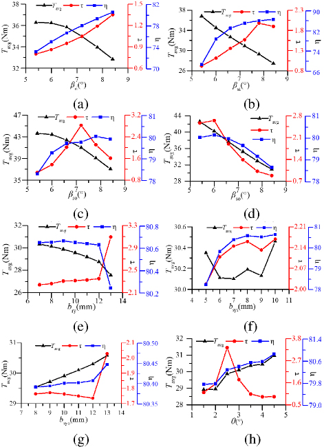
Figure 3: Sensitivity analysis results: (a) rotor inner pole angle, (b) inner stator pole angle, (c) rotor outer pole angle, (d) outer stator pole angle, (e) rotor yoke height, (f) inner stator yoke height, (g) outer stator yoke height, (h) staggered angle of rotor inner and outer teeth.
As shown in Fig. 4, the sensitivity results of each parameter vary greatly while the eight variables lead to a growth of geometric times in sample size for multi-objective optimization.
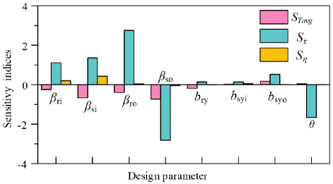
Figure 4: Sensitivity indices of design parameters to the optimization objectives.
Thus, the sensitivity index G(ni) is introduced to measure the significance of each variable [17]. Weight coefficient is applied to evaluate each variable comprehensively considering three optimization objectives and G(ni) is expressed as:
| (4) |
It should be noted that w1, w2 and w3 represent the weight of the average torque, the torque smoothing coefficient and the efficiency, respectively, which satisfy www 1. In this paper, w1 is selected as 0.5, while the value of w2 and w3 are selected to be0.3 and 0.2.
Table 2: Sensitivity of design variables
| Design Parameter | Optimization Objective | G(ni) | ||
| ri | 0.244 | 1.114 | 0.204 | 0.493 |
| si | 0.665 | 1.357 | 0.426 | 0.8009 |
| ro | 0.391 | 2.752 | 0.038 | 0.9934 |
| so | 0.729 | 2.819 | 0.04 | 1.1493 |
| bry | 0.187 | 0.14 | 0.006 | 0.1186 |
| bsyi | 0.02 | 0.137 | 0.052 | 0.0647 |
| bsyo | 0.177 | 0.519 | 0.004 | 0.2277 |
| 0.042 | 1.664 | 0.006 | 0.5178 |
According to (4), the comprehensive sensitivity indices of eight design parameters are calculated as listed in Table 2. The negative sensitivity indices in Table 2 mean that the optimization objectives will come down with the increase of design variables, while the positive sensitivity indices indicate that the optimization objectives will rise with the increase of design parameters. It should be noted that the absolute value of the sensitivity index of the design parameters directly represents their influence on the design objectives. The design parameter with higher absolute value of sensitivity index indicates that the design parameter has a relatively larger influence on the optimization objective. The influence of each design variable on the three design objectives is analyzed and discussed.
For the average torque Tavg , the most sensitive design variable is the outer stator pole angle so, and its sensitivity index is 0.729. The inner stator yoke height bsyi is the least sensitive design variable due to the sensitivity index of 0.02. Moreover, all the pole angles of stator and rotor (rotor inner pole angle ri, inner stator pole angle si, rotor outer pole angle ro and outer stator pole angle so) have significant influence on the average torque of DSSRM. Variation of the stator and the rotor pole angles directly affects the length of the air gap at the unaligned position. Hence, variation of the unaligned inductance further affects the electromagnetic torque of DSSRM, which is mentioned in [19, 20].
It can be observed that the sensitivity indices of pole angles of the outer stator and outer rotor on average torque is larger than that of the inner stator and inner rotor. Note that the total mechanical torque of DSSRM is obtained by the superposition of torque generated by inner and outer motors and they have strong decoupling characteristics. However, the power of the outer motor is greater than the inner motor due to the larger dimensions of the outer motor. Therefore, the influence of the pole angles in outer motor on average torque is greater than the inner stator and inner rotor poleangles.
Additionally, after simple analysis, the most sensitive design variable to the torque smoothing coefficient is the outer stator pole angle so, and its sensitivity index is 2.819. Rotor yoke height bry is the least sensitive design variable because it has the smallest sensitivity index absolute value of 0.14 within the eight design parameters.
Similar with the average torque, all the pole angles of stator and rotor (so, ro, si and ri) significantly influence the torque smoothing coefficient. In addition, the staggered mechanical angle of inner and outer rotor is another significant sensitive parameter to torque smoothing coefficient. It should be noted that total mechanical torque is obtained by the superposition of torque generated by inner and outer motors. The staggered mechanical angle directly affects the staggering degree of the two torque waveforms. Hence, has little influence on the average torque, but has great influence on the torque smoothing coefficient.
It can also be observed that the sensitivity indices of the pole angles of the outer stator and outer rotor on the torque smoothing coefficient is larger than that of the inner stator and inner rotor. Note that the torque output capability of the outer motor is superior to the inner motor due to the larger dimensions of the outer motor.
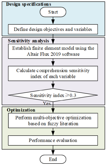
Figure 5: Process of proposed optimization method.
It can be observed that no design variable has a sensitivity index absolute value greater than 0.5. In other words, the eight design variables selected in this paper have relatively small effects on the efficiency of the DSSRM. The phase winding turns, the rotor outer diameter and the conduction angle are the sensitive parameters that have the most significant influence on the efficiency of SRM [21].
The eight design variables are stratified into two levels in this paper. Specifically, ri, si, ro, so and are significant sensitive design variables compared with other variables [G(ni)0.3], which are emboldened in Table 2 and will be further optimized in the next section. Meanwhile, bry, bsyi and bsyo are the nonsignificant variables which have less sensitivity on the three optimization objectives [G(ni)0.3]. Figure 5 illustrates the complete optimization process of the proposed method.
IV. MULTI-OBJECTIVE OPTIMIZATION
This paper adopts a weight determination iteration algorithm based on vector normalization and linear transformation as the optimization method to determine optimal structural parameters of DSSRM. First, an initial decision matrix A (aij)m×n can be constructed by computing the objective value within each parameter variation range, where aij is the attribute value of scheme i under index j [22]. The matrix obtained by the vector normalization method can be expressed as:
| (5) |
The matrix obtained by the linear transformation method is:
| (6) |
Weight coefficient can be expressed as:
| (7) |
The decision result of a certain optimal structure parameter can be obtained by the following formula:
| (8) |
where ui is the adjustment coefficient of the matrix mi(w) and 1-ui is the adjustment coefficient of the matrix Mi(w).
It should be noted that the selected index weight and adjustment coefficient should make the sum of decision results minimum. The weight calculation problem can be converted to the following nonlinear optimization model:
| (9) |
To facilitate the solution, the Lagrange function can be constructed as:
| (10) |
By solving this formula, the following result can be obtained:
| (11) |
The flow chart of the fuzzy iteration algorithm with weight determination is illustrated in Fig. 6.
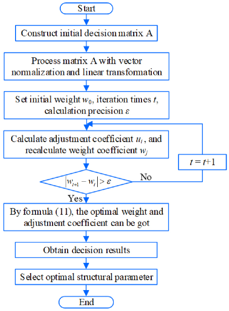
Figure 6: Flow chart of the optimization algorithm.
Taking the staggered angle of rotor inner and outer teeth as an example, the optimization process of the iteration algorithm is described in detail. While keeping other structural parameters unchanged, the average torque Tavg , torque smoothing coefficient and efficiency under different staggered angles are shown in Table 3.
Table 3: Initial decision matrix A of variable
| Value of (∘) | Tavg (Nm) | (%) | |
| 1.5 | 30.45 | 0.90 | 80.59 |
| 2 | 28.95 | 1.54 | 79.79 |
| 2.5 | 29.87 | 3.35 | 80.29 |
| 3 | 30.10 | 1.74 | 80.40 |
| 3.5 | 30.37 | 1.03 | 80.55 |
Using (5) to perform vector normalization processing on matrix A, the results are shown in Fig. 7 (a). Using (6) to perform linear transformation processing on matrix A, the results are shown in Fig. 7 (b). The initial weight is set to w (0.5, 0.3, 0.2) and, after four iterations, the optimal adjustment coefficient and optimal weight coefficient are obtained: u (0.8155, 0.7900, 0.7213, 0.7831, 0.8112), w (0.3068, 0.3886, 0.3046).
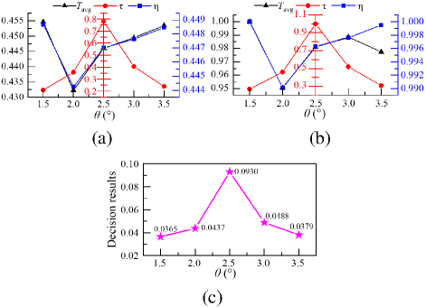
Figure 7: Optimal process with different staggered angles as an example: (a) results of vector normalization, (b) results of linear transformation, (c) final decision results.
Finally, the obtained optimal adjustment coefficient and optimal weight coefficient are substituted into (11), and the final decision results under different staggered angles are shown in Fig. 7 (c). It can be seen that when is 2.5∘, the decision result is the largest within the range, which is 0.0930. For each index weight and scheme adjustment coefficient, bigger decision results represent better performance of a certain decision scheme. Therefore, 2.5∘ is selected as the optimal size of .
Table 4: Final results under different outer stator pole angle so
| so (∘) | 5.4 | 6 | 6.6 | 7.2 | 7.8 |
| Decision Result | 0.0333 | 0.0845 | 0.0591 | 0.0453 | 0.0370 |
Table 5: Final results under different rotor outer pole angle ro
| ro (∘) | 6 | 6.6 | 7.2 | 7.8 | 8.4 |
| Decision Result | 0.0448 | 0.0707 | 0.0560 | 0.0512 | 0.0431 |
After the multi-objective optimization process of the five significant structural variables (one-by-one), the final decision results with so, ro, si, ri and are shown in Tables 4–8, and the optimal structural parameter and decision result of each variable are emboldened. It should be noted that the optimization sequence of these five parameters is determined by the comprehensive sensitivity analysis results in section III. According to the descending order rule of the comprehensive sensitivity index G(ni) values, their optimization sequence is: so, ro, si, ri and . Additionally, based on Table 1, during the optimization process, the initial values for so, ro, si, ri and are all 7.5∘, while the initial value for is 2.5∘. For instance, when so is optimized for single parameter scanning, ro, si and ri are kept at 7.5∘ and is fixed at 2.5∘. When ro is under optimizing, si, ri and remain at their respective initial values (7.5∘, 7.5∘ and 2.5∘), but so adopts its newly optimized value (6∘).
The optimized geometric parameters of DSSRM are summarized in Table 9.
Table 6: Final results under different inner stator pole angle si
| si (∘) | 5.4 | 6 | 6.6 | 7.2 | 7.8 |
| Decision Result | 0.0526 | 0.0616 | 0.0577 | 0.0454 | 0.0493 |
Table 7: Final results under different rotor inner pole angle ri
| ri (∘) | 6 | 6.6 | 7.2 | 7.8 | 8.4 |
| Decision Result | 0.0494 | 0.0523 | 0.0569 | 0.0633 | 0.0467 |
Table 8: Final results under different staggered angle
| (∘) | 1.5 | 2 | 2.5 | 3 | 3.5 |
| Decision Result | 0.0365 | 0.0437 | 0.0930 | 0.0488 | 0.0379 |
Table 9: Final key geometry size of DSSRM
| Item | Variable | Value |
| Outer stator pole angle | so | 6∘ |
| Rotor outer pole angle | ro | 6.6∘ |
| Rotor inner pole angle | ri | 7.8∘ |
| Inner stator pole angle | si | 6∘ |
| Angle of rotor inner and outer teeth | 2.5∘ |
V. SIMULATION AND EXPERIMENTAL VERIFICATION
To verify the proposed multi-objective optimization method, the DSSRM dynamic torque performance at 600 r/min and 1500 r/min in APC (angular position control) mode of the initial size and final size is compared in Fig. 8. It can be observed that the torque performance of the optimized motor is better than that of the benchmark motor at the two operating points.
The performance of the three optimization objectives at 600 r/min is compared in Table 10. It can be seen that the average torque of the DSSRM after optimization increases from 30.17 Nm to 40.99 Nm, the torque smoothing coefficient goes up from 1.78 to 2.82, and the efficiency also increases from 80.80% to 82.46%, and their growth rates are 35.86%, 58.42% and 2.05%, respectively. Hence, the three optimization objectives of the final DSSRM are all improved, but the improvement of efficiency is not as significant as the other two objectives. It should be noted that the design variables selected in this paper have relatively small effects on the efficiency of the DSSRM which has been discussed in section III.
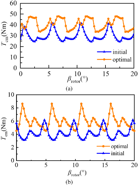
Figure 8: Comparison of electromagnetic torque before and after optimization with APC mode: (a) at 600 r/min and (b) at 1500 r/min.
Table 10: Performance comparison of DSSRM at 600 r/min
| Optimization Objective | Initial Size | Optimized Size | Percentage of Promotion (%) |
| Tavg(Nm) | 30.17 | 40.99 | 35.86 |
| 1.78 | 2.82 | 58.42 | |
| (%) | 80.80 | 82.46 | 2.05 |
In addition, to further verify the presented DSSRM and proposed multi-objective optimization method, the prototype motor experimental platform is established, which is shown in Fig. 9. The rated power of the prototype machine is the same as that of the FE model and the core material of the rotor and stator is 50DW470.
Simulated and measured flux linkage waveforms at the aligned and unaligned position of the prototype machine are shown in Fig. 10. It can be seen that the measured waveform shows good agreement with the FE simulation results, which proves that the multi-objective optimization scheme can effectively improve the performance of DSSRM.
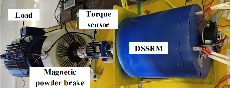
Figure 9: DSSRM prototype experimental platform.
Motor speed is set to 1500 r/min. Turn-on and turn-off angles are fixed at 0∘ and 5∘, respectively. Phase winding current waveforms of the inner and outer stators and motor torque waveforms are shown in Fig. 11. It should be noted that the measured output torque waveform is consistent with the simulation results in Fig. 8 (b), which verifies the effectiveness of the sensitivity analysis and the multi-objective optimization method.
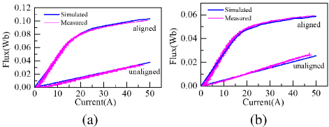
Figure 10: Flux linkage results of experiment and simulation: (a) outer stator and (b) inner stator.
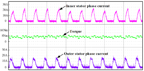
Figure 11: Experimental results of phase current and torque at 1500 r/min.
VI. CONCLUSION
This paper introduces a multi-objective optimization design method of a high performance DSSRM. The initial scheme of the DSSRM is given first. The influence of structural parameters on the optimization objectives of the DSSRM are investigated and discussed in detail. Eight initial design variables are reduced to five significant variables in the optimization process. The final structural parameter scheme of the DSSRM is obtained by applying a weight determination iteration algorithm. Finally, both the simulation and experimental results verify the effectiveness of the sensitivity analysis and proposed multi-objective optimization method.
ACKNOWLEDGMENT
This work is supported by the Jiangsu Science and Technology Plan Special Fund (Innovation Support Plan International Science and Technology Cooperation/ Hong Kong Macao Taiwan Science and Technology Cooperation) Project (BZ2022014), Shenzhen Basic Research Special (Natural Science Foundation) Key Project (JCYJ20220818100000001), 2022 China-CEEC University Joint Education Program (2022200), 2023 China-CEEC University Joint Education Program (2023304).
REFERENCES
[1] M. Abbasian, M. Moallem, and B. Fahimi, “Double-stator switched reluctance machines (DSSRM): Fundamentals and magnetic force analysis,” IEEE Trans. Energy Convers., vol. 25, no. 3, pp. 589-597, Sep. 2010.
[2] M. Asgar, E. Afjei, and H. Torkaman, “A new strategy for design and analysis of a double-stator switched reluctance: Electromagnetics, FEM, and experiment,” IEEE Trans. Magn., vol. 51, no. 12, pp. 1-8, Dec. 2015.
[3] A. H. Isfahani and B. Fahimi, “Comparison of mechanical vibration between a double-stator switched reluctance machine and a conventional switched reluctance machine,” IEEE Trans. Magn., vol. 50, no. 2, pp. 293-296, Feb. 2014.
[4] N. Arbab, W. Wang, C. Lin, J. Hearron, and B. Fahimi, “Thermal modeling and analysis of a double-stator switched reluctance motor,” IEEE Trans. Energy Convers., vol. 30, no. 3, pp. 1209-1217, Sep. 2015.
[5] L. Maharjan, E. Bostanci, S. Wang, E. Cosoroaba, W. Cai, and F. Yi, “Comprehensive report on design and development of a 100-kW DSSRM,” IEEE Trans. Transp. Electrification, vol. 4, no. 4, pp. 835-856, Dec. 2018.
[6] W. Wang, M. Luo, E. Cosoroaba, B. Fahimi, and M. Kiani, “Rotor shape investigation and optimization of double stator switched reluctance machine,” IEEE Trans. Magn., vol. 51, no. 3, pp. 1-4, Mar. 2015.
[7] R. Vandana and B. G. Fernandes, “Design methodology for high-performance segmented rotor switched reluctance motors,” IEEE Trans. Energy Convers., vol. 30, no. 1, pp. 11-21, Mar. 2015.
[8] S. R. Mousavi-Aghdam, M. R. Feyzi, N. Bianchi, and M. Morandin, “Design and analysis of a novel high-torque stator-segmented SRM,” IEEE Trans. Ind. Electron., vol. 63, no. 3, pp. 1458-1466, Mar. 2016.
[9] G. J. Li, X. Y. Ma, G. W. Jewell, and Z. Q. Zhu, “Novel modular switched reluctance machines for performance improvement,” IEEE Trans. Energy Convers., vol. 33, no. 3, pp. 1255-1265, Sep. 2018.
[10] M. A. J. Kondelaji and M. Mirsalim, “Segmented-rotor modular switched reluctance motor with high torque and low torque ripple,” IEEE Trans. Transp. Electrification, vol. 6, no. 1, pp. 62-72, Mar.2020.
[11] W. Yan, H. Chen, Y. Liu, H. Cheng, and M. Orabi, “A magnetic field decoupling double stator switched reluctance machine,” IEEE Trans. Appl. Supercond., vol. 31, no. 8, pp. 1-5, Nov. 2021.
[12] H. Chen, W. Yan, J. J. Gu, and M. Sun, “Multiobjective optimization design of a switched reluctance motor for low-speed electric vehicles with a Taguchi–CSO algorithm,” IEEE/ASME Trans. Mechatronics, vol. 23, no. 4, pp. 1762-1774, Aug. 2018.
[13] P. Di Barba, M. E. Mognaschi, D. A. Lowther, and J. K. Sykulski, “A benchmark TEAM problem for multi-objective Pareto optimization of electromagnetic devices,” IEEE Trans. Magn., vol. 54, no. 3, pp. 1-4, Mar. 2018.
[14] P. Di Barba, F. Dughiero, M. Forzan, D. A. Lowther, M. E. Mognaschi, E. Sieni, and J. K. Sykulski, “A benchmark TEAM problem for multi-objective Pareto optimization in magnetics: The time-harmonic regime,” IEEE Trans. Magn., vol. 56, no. 1, pp. 1-4, Jan. 2020.
[15] G. Bramerdorfer, G. Lei, A. Cavagnino, Y. Zhang, J. Sykulski, and D. A. Lowther, “More robust and reliable optimized energy conversion facilitated through electric machines, power electronics and drives, and their control: State-of-the-art and trends,” IEEE Trans. Energy Convers., vol. 35, no. 4, pp. 1997-2012, Dec. 2020.
[16] R. C. P. Silva, T. Rahman, M. H. Mohammadi, and D. A. Lowther, “Multiple operating points based optimization: Application to fractional slot concentrated winding electric motors,” IEEE Trans. Ind. Electron., vol. 65, no. 2, pp. 1719-1727, Feb.2018.
[17] W. Zhao, A. Ma, J. Ji, X. Chen, and T. Yao, “Multiobjective optimization of a double-side linear Vernier PM motor using response surface method and differential evolution,” IEEE Trans. Ind. Electron., vol. 67, no. 1, pp. 80-90, Jan. 2020.
[18] J. G. Amoros and P. Andrada, “Sensitivity analysis of geometrical parameters on a double-sided linear switched reluctance motor,” IEEE Trans. Ind. Electron., vol. 57, no. 1, pp. 311-319, Jan. 2010.
[19] X. D. Xue, K. W. E. Cheng, T. W. Ng, and N. C. Cheung, “Multi-objective optimization design of in-wheel switched reluctance motors in electric vehicles,” IEEE Trans. Ind. Electron., vol. 57, no. 9, pp. 2980-2987, Sep. 2010.
[20] Y. Zhu, W. Wei, C. Yang, and Y. Zhang, “Multi-objective optimisation design of two-phase excitation switched reluctance motor for electric vehicles,” IET Electr. Power App., vol. 12, no. 7, pp. 929-937, 2018.
[21] K. Diao, X. Sun, G. Lei, Y. Guo, and J. Zhu, “Multiobjective system level optimization method for switched reluctance motor drive systems using finite-element model,” IEEE Trans. Ind. Electron., vol. 67, no. 12, pp. 10055-10064, Dec. 2020.
[22] H. Chen, Y. Zhan, and R. Nie, “Multiobjective optimization design of single-phase tubular switched reluctance linear launcher,” IEEE Trans. Plasma Science, vol. 47, no. 5, pp. 2431-2437, May 2019.
BIOGRAPHIES

Xing Wang received the B.S. degree from China University of Mining and Technology, Xuzhou Jiangsu, China, in 1996, and M.S. degree from China University of Mining and Technology, Xuzhou Jiangsu, in 1999. In 2007, she became an Associate Professor with China University of Mining and Technology, Xuzhou. She is a holder of four US Patents, nine Australian Patents, two Canadian Patents, four Russian Patents, 12 Chinese Invention Patents, three Chinese Utility Model Patents, and has authored 15 papers.

Hao Chen received the B.S. and Ph.D. degrees from the Department of Automatic Control, Nanjing University of Aeronautics and Astronautics, Nanjing, China, in 1991 and 1996, respectively. In 1998, he became an Associate Professor with the School of Information and Electrical Engineering, China University of Mining and Technology, Xuzhou, where he has been a Professor since 2001. From 2002 to 2003, he was a Visiting Professor at Kyungsung University, Busan, Korea. Since 2008, he has also been an Adjunct Professor at the University of Western Australia, Perth, Australia. He is the author of one book and has also authored more than 190 papers. He is the holder of 14 US Patents, 23 Australian Patents, one Danish Patent, seven Canadian Patents, three South African Patents, 10 Russian Patents, 44 Chinese Invention Patents and six Chinese Utility Model Patents. His current research interests include motor control, linear launcher, electric vehicles, electric traction, servo drives and wind power generator control. Chen was the recipient of both the Prize of Science and Technology of Chinese Youth and the Prize of the Fok Ying Tong Education Foundation for Youth Teachers in both 2004. He was awarded the first prize in the Science and Technology advanced of Province and Ministry once, the second prize in the Science and Technology advanced of Province and Ministry seven times, and the third prize in the Science and Technology advanced of Province and Ministry 14 times. He became the Chinese New Century Hundred-Thousand Ten-Thousand Talents Engineering National Talent in 2007 and won the Government Especial Allowance of People’s Republic of China State Department in 2006.

Fengyuan Yu received the Ph.D. degree from the School of Electrical Engineering, China University of Mining and Technology, Xuzhou, China, in 2023. Since 2023, he has been a Post-Doctoral Researcher with the China University of Mining and Technology. His research interests include switched reluctance drive, special motor design, power converters and motor control.

Wenju Yan received the B.S. degree in electrical engineering and automation from the China University of Mining and Technology, Xuzhou, China, in 2013. He received the Ph.D. degree in electrical engineering from the China University of Mining and Technology, Xuzhou, in 2018. From 2019 to 2021, he was a Postdoctoral Research Fellow with China University of Mining and Technology, Xuzhou. Since 2021, he has been an associate professor at the China University of Mining and Technology, Xuzhou. His current research interests include electric vehicles, electric traction, iron loss analysis and special motor design.

Jianfei Pan graduated from the Department of Electrical Engineering of Hong Kong Polytechnic University in Hong Kong with the Ph.D. degree in 2006. Currently he is working in the College of Mechatronics and Control Engineering, Shenzhen University, China. His main research interests are wireless power transfer, electric machine design and control.

Yassen Gorbounov received his B.S., M.S. and Ph.D. degrees from the Sofia University of Technology, Sofia, Republic of Bulgaria, in 2002, 2004, and 2013, respectively. Since 2017, he has been working as an Associate Professor at the Sofia University of Technology. His current research interests include power electronics and the mining industry.
ACES JOURNAL, Vol. 40, No. 9, 810–820
doi: 10.13052/2024.ACES.J.400902
© 2025 River Publishers