Thermal Management of Hybrid Excitation Modular SRM
Xing Wang, Jun Bao, Guoping Wang, Hao Chen, Haidong Yan,
Guanjun Wang, and Jianfei Pan
1International Joint Research Center of Central and Eastern European Countries on
New Energy Electric Vehicle Technology and Equipment
China University of Mining and Technology, Xuzhou 221008, China
3512@cumt.edu.cn, hchen@cumt.edu.cn, poyin_ping@cumt.edu.cn
2Wuxi Institute of Inspection, Testing and Certification
Wuxi 214101, China
jsmtc12@126.com, yhd@wxmtc.com, wgjcumt@126.com
3International Cooperation Joint Laboratory of New Energy Power Generation and
Electric Vehicles of Jiangsu Province Colleges and Universities
Xuzhou 221008, China
4Jiangsu Province Foreign Expert Workshop on New Energy
Power Generation and Electric Transportation
Xuzhou 221008, China
5Shenzhen Research Institute
China University of Mining and Technology
Shenzhen 518057, China
6School of Electromechanical and Control Engineering
Shenzhen University, Shenzhen 518054, China
pjf@szu.edu.cn
Submitted On: December 24, 2024; Accepted On: May 29, 2025
ABSTRACT
This paper explores the effect of modular structure on the thermal management performance of switched reluctance motors. By designing the modular structure, combined with the centralized winding and parallel slot configuration, the heat dissipation capability of the motor is significantly improved without affecting the torque performance of the motor. Meanwhile, the effect of thermal management on the demagnetization behavior of permanent magnets, especially the mechanism of action when forming mixed excitation, is investigated. Finally, the thermal performance of the motor and the demagnetization characteristics of the permanent magnets are comprehensively analyzed by temperature field simulation, which provides an important basis for the optimized design of the motor.
Index Terms: Electromagnetic simulation, hybrid excitation, modular structure, switched reluctance motor, thermal management.
I. INTRODUCTION
Switched reluctance motors are widely used in industrial production, aerospace and other fields due to their simple structure, high starting torque and adaptability to harsh environments. Although switched reluctance motors have certain advantages in thermal management due to their simple structure, with the increasing power density, the thermal management problem has become more and more prominent and has become a key challenge to be solved.
In order to increase the power density, an effective approach is to increase the current density and optimize the structural design, but this correspondingly raises the requirements for thermal management [1]. However, excessive current density can lead to a significant increase in iron and hysteresis losses, which can lead to overheating problems in the windings and core. Most motors are air-cooled at the design stage by optimizing the structure for heat dissipation, creating a passive heat dissipation mechanism. This method utilizes the gap between the motor structure and the shell to emit heat. This is effective, but the heat transfer process is slow. Therefore, the limiting conditions of current density and magnetic density of switched reluctance motors must be fully considered at the early design stage. This approach usually reduces motor performance to some extent. Another solution is to use active cooling technology, which provides thermal management by adding specialized cooling components. For example, integrating a liquid-cooled component in the motor stator allows for rapid and efficient heat extraction from heat sources close to the motor’s interior, such as the windings [2]. Although this method is more efficient in terms of heat dissipation, it has a higher design cost and makes the motor structure more complex, which is not conducive to fully utilizing the advantages of the simple structure of switched reluctance motors.
Passive heat dissipation through the motor structure requires more structural design space in order to facilitate heat dissipation, especially ensuring the stator has enough space for heat dissipation. In [3] the authors simulated and investigated the temperature rise due to electromagnetic losses in switched reluctance motors and verified the temperatures in various parts of the machine through experimental data. In [4] the authors calculated the thermal parameters of an induction motor under totally enclosed fan-cooled conditions, and these calculations are able to be transferred to switched reluctance motors. It can be seen that for passive cooling, switched reluctance motors are more advantageous because the windingless rotor structure improves the ability to dissipate heat, especially if the convex pole rotor can provide some functions of a fan.
The stator can be wound with a centralized winding which has a lower winding density than other motors. Modularization of the stator is a well-established method to solve the thermal management problem by reducing the stator yoke core to leave enough space for passive heat dissipation. In [5], the authors calculate the temperature distribution of a two-stator switched reluctance motor at a constant temperature, simplifying the calculation and time. The effect of different winding connections on the temperature rise of the switched reluctance motor (SRM) was analyzed in the literature [6], and it was demonstrated that the two parallel path approach for one phase produces a significant temperature reduction.
Although the modular structure can effectively enhance the thermal management performance of SRMs, it will also have some impact on the overall performance of the motor. To enhance the performance of SRMs, hybrid excitation using permanent magnets is an effective improvement method. However, this design also faces the risk of permanent magnet demagnetization due to temperature rise. In [7], authors analyze the demagnetization characteristics of permanent magnets in modular radial hybrid excitation switched reluctance motors and point out that its structural design can make the risk of demagnetization of permanent magnets do not increase significantly when the current exceeds more than double the rated value.
In this paper, a modular double-stator hybrid excitation switched reluctance motor is designed and its stator-rotor and winding distribution structure is optimized. Meanwhile, the influence of the temperature rise effect on the demagnetization performance of permanent magnets is analyzed in detail through thermal simulation of the core and windings, which provides an important reference for motor design and thermal management.
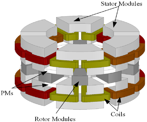
Figure 1: AFMHSRM topology diagram.
II. TOPOLOGY DESIGN OF SWITCHED RELUCTANCE MOTOR
The three-phase 12/10 axial flux modular hybrid-excitation SRM (AFMHSRM) proposed in this paper is shown in Fig. 1. The stator of the AFMHSRM consists of 12 annularly arranged U-shaped stator modules, each with two stator poles and two stator slots. The rotor is secured by 10 rotor module mounting disks. As shown in Fig. 1, the left and right stators are positioned on either side of the rotor. Both the stator and rotor are constructed from DW470 laminated silicon steel sheets. The motor adopts concentrated windings, which not only saves space for the windings but also provides more room for the stator mounting plates, thereby facilitating easier installation and disassembly. Each phase contains four windings, which are independently connected and can be configured in either series or parallel to adjust the motor’s operating characteristics. Notably, the stator and rotor are designed with parallel slots, allowing windings of equal area to be placed in slots of different radii. In addition, permanent magnets are embedded as modules between the U-shaped stator segments to enhance torque density.

Figure 2: Dimensional schematic of AFMHSRM: (a) axial dimensions and (b) inner and outer diameters and rotor pole angle.
Performance specifications of the AFMHSRM are given in Table 1. The AFMHSRM has been designed by using a modular design in order to minimize the cost and at the same time increase the heat dissipation volume. The centralized winding and parallel slot structure are adopted on the stator, which minimizes the winding gap and improves heat dissipation uniformity in the slots, while the modular stator structure increases the passive heat dissipation space and area. The stator-rotor axial as well as circumferential dimensions of the proposed motor are given schematically in Fig. 2 (a). To define the rotor’s radial dimensions for the proposed motor, it is necessary to add the initial conditions. These include the motor’s inner and outer diameters as well as the rotor’s polar arc angle. The specific values for these dimensions are provided in Table 2.
Table 1: Design requirements of AFMHSRM
| Parameter | Symbol | Value |
| Rated voltage (V) | U | 96 |
| Rated power (W) | P | 1200 |
| Rated speed (r/min) | n | 600 |
| Stator-rotor outer diameter (mm) | Do | 175 |
| Current density (A/mm2) | Id | 6 |
| Stack length (mm) | L | 96.8 |
Table 2: Design requirements of AFMHSRM
| Item | Parameter | Value |
| Stator-rotor outer diameter (mm) | Do | 175 |
| Stator-rotor inner diameter (mm) | Di | 101 |
| Rotor polar arc angle (∘) | 15.5 | |
| Stator yoke height (mm) | lsy | 14 |
| Stator pole length (mm) | lsp | 26 |
| Rotor pole length (mm) | lrp | 15.5 |
| Stator slot width (mm) | wsp | 20 |
| Permanent magnets length (mm) | lpm | 6 |
| Air gap length (mm) | g | 0.4 |
| Stack length (mm) | L | 96.8 |
III. MOTOR LOSS ANALYSIS AND CALCULATION
The temperature rise of switched reluctance motors is mainly caused by the conversion of copper and iron losses generated during motor operation into heat energy. Heat energy accumulates inside the motor, causing the temperature to rise and adversely affecting the operational performance and reliability of the motor. Modeling and accurate calculation of copper and iron losses in motors is an important part of thermal management analysis.
Copper loss is closely related to winding resistance, operating current and motor speed. Under high-speed operating conditions, the skin effect and proximity effect will further increase the copper loss. Elevated temperatures further change the material resistivity of the windings, affecting the dynamic characteristics of copper losses.
Iron losses occur mainly in the stator and rotor cores, and consist of hysteresis losses, eddy current losses and additional losses. Among them, hysteresis loss is related to the hysteresis loop characteristics of magnetic materials and the change of magnetic flux density. Eddy current loss is caused by the eddy current induced by the alternating magnetic field inside the core, and its magnitude is related to the magnetic flux frequency, the conductivity of the core material and the thickness of the sheet. Additional loss includes that caused by high harmonics, leakage flux and other complex factors, and its calculation usually needs to be corrected by combining electromagnetic simulation with experimental data.
A. Calculation of iron loss
Currently, iron loss is mainly calculated by the magnetic circuit analysis method and the finite element method. The iron loss of ferromagnetic materials is categorized into eddy current loss and hysteresis loss and, in general, the basic loss is obtained from the empirical formula calculated at the industrial frequency [8]:
| (1) |
where PFe is motor iron loss per unit mass loss; Ph and Pe are hysteresis loss and eddy current loss, respectively; Ch and Ce are core hysteresis loss coefficient and eddy current loss coefficient, respectively, related to the material coefficient of the iron core and the level of technology; n 1.62.2, related to the size of Bm. Ch and Ce can be obtained by parameterization of the frequency of 50 Hz and 60 Hz [9].
A switched reluctance motor has strong nonlinearity. Its instantaneous iron core loss is non-sinusoidal periodic changes, so the need for Fourier decomposition of equation (1), the non-sinusoidal magnetic field kth harmonic iron loss estimation formula, is obtained as follows:
| (2) |
where Ph(k) and Pe(k) are unit hysteresis loss and eddy current loss, respectively; f is core magnetically dense fundamental frequency, which is related to motor speed and number of stator and rotor poles; and Bkmax and Bkmin are kth harmonic radial and tangential Fourier transform amplitudes.
If the effect produced by the higher harmonics is negligible, then equation (2) can be rewritten as:
| (3) |
In a sinusoidal magnetic field, when the volume of the motor core is fixed, motor iron loss, hysteresis loss Ph and eddy current loss Pe are proportional to magnetic field frequency f as well as f2. Let magnetic density be B, iron loss per unit volume is:
| (4) |
When f, a(B) and b(B) are all fixed, equation (4) can be rewritten as:
Copper loss of the winding is the main cause of temperature rise of the motor. The motor structure designed in this paper leaves more space for heat dissipation of the motor winding. Heat generation of the winding is related to the rms value of the current through the winding, which can be expressed as:
| (6) |
where PT denotes the copper loss of the torque winding, It denotes the rms value of the current and Rt denotes the resistance of the winding.
The motor winding can be estimated by the following equation:
| (7) |
where is the resistivity, l is the length of one winding conductor and S is the cross-sectional area of the conductor.
Winding heat generation rate Q can be expressed as:
| (8) |
where Q is the winding heat generation rate and VT is the winding volume.
C. Electromagnetic simulation of motors for loss analysis
A 3-D model of the proposed AFMHSRM is built in Ansys/Maxwell FEA software and the parameters of the stator and rotor cores, permanent magnets and windings are set to obtain the magnetic density cloud of the AFMHSRM as shown in Fig. 3 when the windings are excited by a constant current of 30 A. At the same time, the conventional 12/10 axial flux switched reluctance motor is finite element analyzed and compared with the AFMHSRM, and its magnetic density cloud is shown in Figs. 3 and 4.
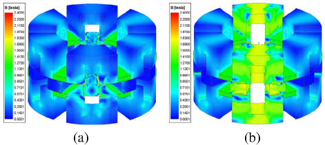
Figure 3: Flux density distribution maps of AFMHSRM: (a) unaligned position and (b) aligned position.
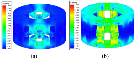
Figure 4: Flux density distribution maps of CAFSRM: (a) unaligned position and (b) aligned position.

Figure 5: Comparison of iron loss and eddy current loss of two motors: (a) stator iron loss, (b) rotor iron loss, (c) permanent magnets eddy current loss.
It can be seen that the magnetic density of the AFMHSRM at the stator poles is significantly higher than that of the conventional AFSRM for its position. On the contrary, the magnetic density at the stator yoke is lower than that of the CAFSRM due to the flux canceling effect of the permanent magnets. Therefore, the AFMHSRM produces less core loss in the stator than the CAFSRM.
The stator and rotor iron losses of both motors at rated condition and the eddy current loss curves of AFMHSRM are given in Fig. 5. It can be seen that the stator iron loss and rotor iron loss of the AFMHSRM are lower than that of the CAFSRM, which is attributed to permanent magnet flux reduction stator yoke magnetization and modular stator structure.
IV. MOTOR THERMAL MANAGEMENT ANALYSIS
A switched reluctance motor conducts heat from its windings and core through the air and core to the surface during operation. The thermal conductivity equation of a motor under steady conditions can be written as:
| (9) |
where T is the internal temperature of the motor, qi is the sum of heat flow densities, is the motor running time, is the density of the motor material, c is specific heat capacity of the motor material, and kx, ky and kz are the coefficients of thermal conductivity in the x, y and z directions of the axes, respectively.
In a steady state temperature field, temperature does not change with time and the right-hand side of the equation is 0. If the transient temperature field is analyzed, it is necessary to add boundary conditions for the initial moment.
First type of boundary conditions:
| (10) |
Second type of boundary conditions:
| (11) |
Third type of boundary conditions:
| (12) |
where T0 is the surface temperature value given by the first type of boundary condition; q0 is the heat flow density given by the second type of boundary condition, the magnitude of which is related to the nature of the motion of the fluid flowing over the surface; the third type of boundary condition is the heat transfer coefficient and temperature of the object on both sides of the given boundary; S1, S2 and S3 are boundary surfaces, kq is the boundary thermal conductivity, q is the heat transfer coefficient and Tf is the temperature around the heat dissipation surface.
A. Thermal analysis of AFMHSRM
With the stator and rotor iron losses obtained in the previous section, as well as the eddy current losses of the permanent magnets, the thermal model of the proposed AFMHSRM is further constructed, and the model is thermally analyzed using Ansys Workbench. In order to ensure the accuracy of the thermal analysis, and without considering the material changes with temperature, the following key operations need to be completed in the preliminary stage.
1. Temperature field model
The three-dimensional model of the motor established in the electromagnetic analysis stage is directly imported into the temperature field model, while ensuring that the physical parameters (density, thermal conductivity) of each part of the material in the imported model are consistent with the original settings, in order to ensure the reliability of the electromagnetic-thermal coupling analysis.
2. Grid division and parameter setting
Reasonable grid division is carried out for the imported 3D model to ensure the balance between calculation accuracy and solving efficiency. Loss data (including stator iron loss, rotor iron loss and permanent magnet eddy current loss) obtained from previous calculations are input into the simulation initialization parameters as heat sources, and reasonable heat dissipation boundary conditions and heat dissipation coefficients are added according to the actual cooling conditions and motor structure characteristics.

Figure 6: Mesh graph of the 3D thermal model of the motor: (a) overall sectional view and (b) stator side.


Figure 7: Temperature map of AFMHSRM motor: (a) winding, (b) stator and (c) rotor.
3. Thermal model solving and condition analysis
Based on the defined heat source and heat dissipation conditions, the thermal model is solved to obtain the steady state and transient heat distribution results. On this basis, the temperature distribution and thermal gradient changes of key components (e.g. stator windings, rotor and permanent magnets) are analyzed under different working conditions, which provides reference for the subsequent optimization of the motor structure and design of the cooling system.
A 3D sectional view of the entire motor during thermal simulation is given in Fig. 6. The simulation compensation is set to 1000 s and the loss parameters derived from the EM simulation are entered. The temperature distribution of stator, rotor and winding of the proposed motor at a constant initial temperature of 25∘C is given in Fig. 7.
It can be seen that due to the high copper loss of the windings, the internal heat of the windings is difficult to be distributed. The temperature in the internal center area is significantly higher, with the maximum temperature reaching about 44∘C. Compared to a significantly lower temperature, the heat of the motor stator is mainly concentrated in the stator pole part. The intimate heat dissipation about the temperature generated by the windings is transferred to the stator yoke through the stator poles and is distributed to the air, and the temperature in the center of the stator poles is slightly lower than that in the stator poles. The temperature at the center of the stator pole is a little lower than that of the windings. At the same time the rotor temperature is well suppressed.
V. CONCLUSION
In this paper, the influence of the structural design of the proposed AFMHSRM motor on its temperature rise is analyzed through simulation, and the copper loss and iron loss of the proposed AFMHSRM are obtained through finite element simulation. A temperature field simulation model is constructed through copper loss and iron loss, and it is verified that the temperature of the structure of the proposed motor stays at the non-high-temperature degree of 44∘C, which is attributed to the thermal structure of the motor as well as the control of the electric density. It can be seen that the proposed motor has obvious advantages in thermal management.
ACKNOWLEDGMENT
This work is supported by the Jiangsu Science and Technology Plan Special Fund (Innovation Support Plan International Science and Technology Cooperation/ Hong Kong Macao Taiwan Science and Technology Cooperation) Project (BZ2022014), Jiangsu Provincial Market Supervision Administration Science and Technology Plan Project (KJ2025017), Shenzhen Basic Research Special (Natural Science Foundation) Key Project (JCYJ20220818100000001), 2022 China-CEEC University Joint Education Program (2022200), 2023 China-CEEC University Joint Education Program (2023304) and Jiangsu Province Modern Agricultural Machinery Equipment and Technology Demonstration and Promotion Project (NJ2023-27).
REFERENCES
[1] B. Bilgin and A. Emadi, “Electric motors in electrified transportation: A step toward achieving a sustainable and highly efficient transportation system,” IEEE Power Electron. Mag., vol. 1, no. 2, pp. 10-17, June 2014.
[2] C. Rhebergen, B. Bilgin, A. Emadi, E. Rowan, and J. Lo, “Enhancement of electric motor thermal management through axial cooling methods: A materials approach,” in European Conference on Cognitive Ergonomics, pp. 5682-5688, Sep. 2015.
[3] J. Faiz, B. Ganji, C. E. Carstensen, K. A. Kasper, and R. W. De Doncker, “Temperature rise analysis of switched reluctance motors due to electromagnetic losses,” IEEE Trans. Magn., vol. 45, no. 7, pp. 2927-2934, June 2009.
[4] A. Boglietti, A. Cavagnino, M. Lazzari, and M. Pastorelli, “A simplified thermal model for variable-speed self-cooled industrial induction motor,” IEEE Trans. on Ind. Applicat., vol. 39, no. 4, pp. 945-952, July 2003.
[5] N. Arbab, W. Wang, C. Lin, J. Hearron, and B. Fahimi, “Thermal modeling and analysis of a double-stator switched reluctance motor,” IEEE Trans. Energy Convers., vol. 30, no. 3, pp. 1209-1217, May 2015.
[6] S. Arjun and N. C. Lenin, “Impact of coil arrangements on the electromagnetic and thermal performance of a switched reluctance motor at low speeds,” in IEEE International Conference on Power System Technology, pp. 1-6, Sep. 2022.
[7] M. A. Jalali Kondelaji, E. F. Farahani, and M. Mirsalim, “Teethed-pole switched reluctance motors assisted with permanent magnets: analysis and evaluation,” IEEE Trans. Energy Convers., vol. 36, no. 3, pp. 2131-2140, Sep. 2021.
[8] J. Zhang, H. Wang, L. Chen, C. Tan, and Y. Wang, “Salient pole rotor with partially covered shrouds for the windage loss reduction of bearingless switched reluctance motors,” in 2018 13th IEEE Conference on Industrial Electronics and Applications (ICIEA), pp. 868-873, May 2018.
[9] N. J. F. Liu, N. X. Zhang, H. J. Wang, and N. J. F. Bao, “Iron loss characteristic for the novel bearingless switched reluctance motor,” in International Conference on Electrical Machines and Systems, pp. 586-591, Oct. 2013.
BIOGRAPHIES

Xing Wang received the B.S. degree from China University of Mining and Technology, Xuzhou Jiangsu, China, in 1996, and M.S. degree from China University of Mining and Technology, Xuzhou Jiangsu, in 1999. In 2007, she became an Associate Professor with China University of Mining and Technology, Xuzhou. She is a holder of four US Patents, nine Australian Patents, two Canadian Patents, four Russian Patents, 12 Chinese Invention Patents, three Chinese Utility Model Patents, and has authored 15 papers.

Jun Bao was born in August 1971. He is a Full Senior Engineer, currently serving as the director of Wuxi Institute of Inspection, Testing and Certification. His primary research areas include inspection and testing technologies for new energy vehicles, as well as metrological test technologies.

Guoping Wang received the B.S. degree and M.S. degree from the School of Electronic and Information Engineering, Anhui University of Science and Technology, Huainan, China, in 2018 and 2021, respectively. He is currently pursuing the Ph.D. degree in the electrical engineering at China University of Mining and Technology, Xuzhou. His research interests include optimal design and control of switched reluctance machines.

Hao Chen (SM’08) received the B.S. and Ph.D. degrees from the Department of Automatic Control, Nanjing University of Aeronautics and Astronautics, Nanjing, China, in 1991 and 1996, respectively. In 1998, he became an Associate Professor with the School of Information and Electrical Engineering, China University of Mining and Technology, Xuzhou, China, where he has been a Professor since 2001. From 2002 to 2003,he was a Visiting Professor at Kyungsung University, Busan, Korea. Since 2008, he has also been an Adjunct Professor at the University of Western Australia, Perth, Australia. He is the author of one book and has also authored more than 190 papers. He is the holder of 14 US Patents, 23 Australian Patents, one Danish Patent, seven Canadian Patents, three South African Patents, 10 Russian Patents, 44 Chinese Invention Patents and six Chinese Utility Model Patents. His current research interests include motor control, linear launcher, electric vehicles, electric traction, servo drives, and wind power generator control. Chen was the recipient of both the Prize of Science and Technology of Chinese Youth and the Prize of the Fok Ying Tong Education Foundation for Youth Teachers in both 2004. He was awarded the first prize in the Science and Technology advanced of Province and Ministry once, the second prize in the Science and Technology advanced of Province and Ministry seven times, and the third prize in the Science and Technology advanced of Province and Ministry 14 times. He became the Chinese New Century Hundred-Thousand Ten-Thousand Talents Engineering National Talent in 2007 and won the Government Especial Allowance of People’s Republic of China State Departmentin 2006.

Haidong Yan was born in May 1982. He has a master’s degree in System Analysis and Integration from Nanjing University of Information Science & Technology, Nanjing, China. He is a Senior Engineer currently serving as the deputy director of Wuxi Institute of Inspection, Testing and Certification. His research direction mainly focuses on electromagnetic metrology, new energy vehicle specialized metrology and testing technology.

Guanjun Wang was born in September 1986. He has a master’s degree in Electronic and Communication Engineering from China University of Mining and Technology, Xuzhou, China. He is a Senior Engineer currently serving as the director of Electrical and information M&R Department of Wuxi Institute of Inspection, Testing, and Certification. His research direction mainly focuses on electromagnetic metrology, new energy vehicle specialized metrology and testing technology.

Jianfei Pan (Member, IEEE) graduated from Department of Electrical Engineering of Hong Kong Polytechnic University in Hong Kong with a Ph.D. degree in 2006. Currently he is working in the College of Mechatronics and Control Engineering, Shenzhen University, Shenzhen, China. His main research interests are wireless power transfer, electric machine design and control.
ACES JOURNAL, Vol. 40, No. 9, 953–961
doi: 10.13052/2024.ACES.J.400916
© 2025 River Publishers