Design and Analysis of Modular Transverse Flux Dual-rotor Switched Reluctance Motor
Hemiao Liu, Xing Wang, Hao Chen, Jun Bao, Haidong Yan, Guanjun Wang, and Yassen Gorbounov
1School of Electrical Engineering
China University of Mining and Technology, Xuzhou 221116, China
TB22230006A41@cumt.edu.cn, hchen@cumt.edu.cn
2International Joint Research Center of Central and Eastern European Countries on New Energy Electric Vehicle Technology and Equipment
Xuzhou 221008, China
3512@cumt.edu.cn
3International Cooperation Joint Laboratory of New Energy Power Generation and Electric Vehicles of Jiangsu Province Colleges and Universities
Xuzhou 221008, China
4Jiangsu Province Foreign Expert Workshop on New Energy Power Generation and Electric Transportation
Xuzhou 221008, China
5Shenzhen Research Institute
China University of Mining and Technology, Shenzhen 518057, China
6Wuxi Institute of Inspection, Testing and Certification
Wuxi 214101, China
jsmtc12@126.com, yhd@wxmtc.com, wgjcumt@126.com
7New Bulgarian University
Sofia, Bulgaria
y.gorbounov@mgu.bg
Submitted On: June 13, 2024; Accepted On: July 25, 2025
ABSTRACT
The present study proposes a novel modular transverse flux dual-rotor switched reluctance motor (MTF-DRSRM), which integrates the operational principles of switched reluctance motors (SRMs) with the structural advantages of transverse flux machines (TFMs). The motor employs H-shaped modular stator cores and segmented rotor discs with embedded pole modules, employing toroidally-wound concentrated windings for excitation. Compared to conventional SRMs, the MTF-DRSRM leverages the transverse flux configuration to enable flexible decoupling of electric and magnetic loads. This design effectively enhances torque density and operational efficiency, making it suitable for high-performance drive applications such as electric vehicles. This paper introduces the fundamental structure, operational principles, and electromagnetic design methodology of the MTF-DRSRM. Due to the three-dimensional distribution of the motor’s magnetic field, 3D magnetic field computation using finite element analysis (FEA) is employed to calculate key parameters, including magnetic flux linkage and torque characteristics. The design validation is performed by comparing theoretical parameters with 3D-FEA simulation results, ensuring accuracy and reliability. This work provides a robust theoretical foundation and empirical data for further optimization and practical implementation of the proposed motor topology.
Index Terms: Electromagnetic design, finite element analysis, modular structure, switched reluctance motor, transverse flux.
I. INTRODUCTION
Switched reluctance motors (SRMs) are characterized by structural simplicity, high reliability, flexible control, operational efficiency, and exceptional suitability for high-speed and harsh-environment applications. The development potential and performance advantages of SRM-based drive systems have reignited global research interest in this technology [1–2]. However, as application scenarios grow increasingly complex and performance requirements become more stringent, conventional SRMs exhibit limitations in critical metrics such as torque density and efficiency.
The advent of the transverse flux machine (TFM) concept has ushered in a novel paradigm for motor design, offering a distinctive magnetic field distribution pattern that has the potential to enhance torque density and generate more powerful torque within a confined space [3–4]. The incorporation of a dual rotor configuration serves to enhance the motor’s energy conversion mechanisms and torque generation capabilities. This is achieved by leveraging the delicate electromagnetic interaction between the inner and outer rotors and the stator, thereby ensuring an overall enhancement in the motor’s performance across all domains [5].
Current research efforts have historically concentrated energies on theoretical research, structural design, and control strategy in the domain of transverse flux switched reluctance motor research. Literature [6–7] utilizes finite element analysis (FEA) and other methods to model and analyze the internal magnetic field distribution of the motor, thereby facilitating the comprehension of the magnetic field strength, direction, and change rule. This, in turn, provides a theoretical foundation for the optimization of motor design. Research findings indicate that the introduction of transverse flux alters the magnetic field distribution, thereby affecting the electromagnetic performance of the motor. Literature [8–9] established a mathematical model that can accurately describe the electromagnetic characteristics of the motor and mechanical characteristics. The equivalent magnetic circuit method was used to establish mathematical models that can be used to analyze the dynamic performance of the motor, including speed, torque, current, and other parameters of the law of change. Concurrently, a series of innovative topologies have been proposed, including double U-shaped stator cores, I-type stator core, and U-type rotor core fit, with the objective of enhancing the motor’s output torque, power density, and other performance metrics. These topologies have been shown to improve magnetic circuit coupling by increasing the number of poles and phases and by increasing the rotor radius to improve the output torque. As evidenced by the existing literature [10-11], the optimization of winding form, the number of turns, wire diameter, and other relevant parameters has been shown to reduce winding loss, thereby enhancing motor efficiency and power factor. This enhancement is achieved through the implementation of various winding configurations, including centralized and distributed winding, which have been studied in depth to ascertain their impact on motor performance. In the realm of control strategies, [12–13] have been instrumental in refining conventional methodologies such as current chopper control and angular position control. These refinements have been undertaken to mitigate torque pulsation, reduce noise, and enhance the smoothness and comfort of the motor. For instance, the optimization of frequency, amplitude, and other parameters of the current chopper has been a focal point of these studies. Concurrently, [14] explores the implementation of advanced intelligent control methodologies, including fuzzy control, neural network control, and sliding mode variable structure control, in transverse flux switched reluctance motors. The objective of these investigations is twofold: first, to enhance the control accuracy, response speed, and robustness of the motors and, second, to optimize their performance in complex working conditions, thereby ensuring the fulfillment of stringent control requirements.
This paper synthesizes the advantages of axial-field and conventional radial-field switched reluctance motors and proposes a modular transverse-flux dual-rotor switched reluctance motor. The motor is distinguished by a split-block rotor fixed on both sides of the motor on their respective rotor disks and a toroidally-wound concentrated winding. The space utilization of the stator part of this novel structure motor is greater in comparison to the traditional structure SRM, while the winding end effect is diminished. The rotor shaft utilizes a non-conducting material, which shortens the magnetic circuit and reduces the inter-pole magnetic leakage. The main features of a modular transverse flux dual-rotor switched reluctance motor (MTF-DRSRM) are asfollows.
-
The motor possesses greater space for winding storage and more flexible turn design. The stator and rotor are small and have shorter magnetic paths, which improves the motor efficiency.
-
Individual windings are wound on the iron core, with reduced electromagnetic interference, facilitated heat dissipation, and simplified maintenance and winding.
-
The motor’s design is modular and highly expandable, allowing for adjustment of the number of phases and poles to increase output torque.
II. STRUCTURE AND OPERATING PRINCIPLE OF MTF-DRSRM
This paper presents an analytical study on the design of a three-phase 12/8-pole MTF-DRSRM. As shown in Fig. 1, the stator employs a segmented configuration comprising 12 identical H-shaped laminated cores with toroidally-wound excitation coils, where three consecutive coils constitute the three-phase (ABC) excitation system. Each modular unit integrates multiple concentrated windings wound on specially profiled stator teeth, whose geometric parameters are optimized to enhance magnetic circuit efficiency and torque density. These stator segments maintain electromagnetic independence while being circumferentially symmetrical distributed, offering advantages in manufacturability, assembly, and maintenance, as well as flexible phase configuration adaptability. The rotor adopts a dual-rotor disc topology coaxially arranged with the stator, featuring eight ferromagnetic pole segments embedded in each rotor disc through precision-machined slots. Both stator and rotor cores are fabricated using grain-oriented silicon steel laminations processed by stacked lamination techniques. This manufacturing approach significantly facilitates modular production methodologies through standardized component design.
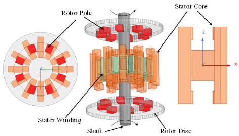
Figure 1: Structure of three-phase 12/8-pole MTF-DRSRM.
When three-phase stator windings are electrically excited, magnetic flux is established through the stator teeth. As shown in Fig. 2, the MTF-DRSRM’s magnetic circuit topology utilizes an H-shaped segmented core module in the stator, which magnetically couples with radially arranged dual rotor discs to form a closed magnetic path. At the stator-rotor unmagnetized position in Fig. 2 (a), the winding inductance reaches its minimum value. During this phase, DC pulse excitation is applied to the windings, establishing magnetic flux. Owing to the transverse flux path configuration, the magnetic flux predominantly traverses in the axial direction through stator teeth and rotor poles, inducing magnetic field distortion at rotor pole edges. This phenomenon generates reluctance torque that drives rotor rotation toward the aligned position. In the stator-rotor magnetized equilibrium position in Fig. 2 (b), the rotor poles align with the stator magnetic axis to minimize the magnetic reluctance path. Compared to conventional radial-flux switched reluctance motors (SRMs), the MTF-DRSRM demonstrates significantly reduced winding overhang leakage flux, thereby improving magnetic circuit utilization efficiency. The compact axial dimension of the rotor enables high-speed operation (typically exceeding 10,000 rpm) and high specific power output. Additionally, the dual-rotor coaxial topology amplifies torque production through parallel magnetic circuit actuation, achieving torque superposition effects.
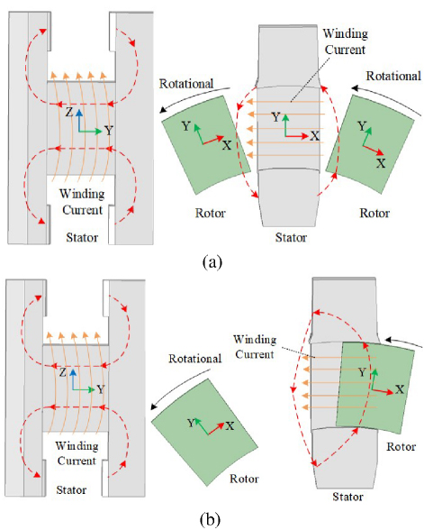
Figure 2: Main magnetic circuit of the MTF-DRSRM: (a) stator and rotor misaligned position and (b) stator and rotor alignment position.
III. MAIN DIMENSIONS DESIGN OF MTF-DRSRM
The width and height of the stator teeth have a significant effect on the magnetic chain and torque of the motor. The number of turns of the stator winding determines the inductance and resistance of the winding, which in turn affects the current magnitude, torque, and efficiency of the motor. A reasonable selection of the number and angle of rotor teeth can reduce torque pulsation and improve the smoothness of motor operation. The thickness of the rotor core has been found to influence the magnetic field strength and the degree of magnetic circuit saturation of the motor. An excessively thin rotor core may lead to saturation of the magnetic circuit and reduce the performance of the motor, while an excessively thick core will increase the weight and cost of the motor. Therefore, it is necessary to design the parameters of MTF-DRSRM. Figure 3 provides a schematic representation of the stator and rotor cores of MTF-DRSRM for dimensioning purposes.
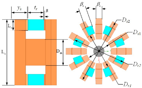
Figure 3: Schematic illustration of stator and rotor core dimensioning for MTF-DRSRM.
According to Kirchhoff’s law, the voltage equation of MTF-DRSRM for any phase can be derived:
| (1) |
where u is the terminal voltage, R is the stator resistance, i is the stator current, is the magnetic chain, L is the inductance.
During rotor-stator tooth overlap, a period of significant inductance changes where the inductive reactance dominates, the resistance R can be neglected for steady-state analysis. Equation (1) can thus be simplified to:
| (2) |
where is the rotating mechanical angular velocity of the motor, La is the aligned position inductance, Lu is the unaligned position inductance, is the stator pole arc.
Let us define k as the ratio of the inductance La at the aligned position to the inductance Lu at the unaligned position:
| (3) |
Then, equation (2) can be rewritten as:
| (4) |
When the stator and rotor are aligned, the expression for the magnetic chain is:
| (5) |
where sp is the average magnetic density of the surface of the stator pole section at the aligned position, initially assumed to be 1.6 T. Asp is the cross-sectional area of the stator pole and Nph is the number of windings turns per phase of the motor.
MTF-DRSRM’s adopt a double rotor structure and its stator cross-sectional area can be expressed as:
| (6) |
where Dr1 is the rotor inner diameter and Lr is the rotor pole yoke thickness.
In the motor design, the rotor axial width tr must be carefully controlled. On the one hand, tr impacts overall motor volume; on the other, it influences coil slot fullness. Therefore, at the initial design stage, the rotor axial width is set equal to the stator axial width ys, that is:
| (7) |
According to equations (4-6):
| (8) |
Electrical load expression of the MTF-DRSRM can be written as:
| (9) |
where m is the number of phases and Ds1 is the stator inner diameter. The initial assumed electrical load is 50000 A/m.
The load factor for switching one cycle of each phase of the winding is:
| (10) |
where Nr is the number of rotor poles and c is the opening angle of each phase.
The motor output power is:
| (11) |
where is motor efficiency.
Substituting equations (6-8) into equation (9), the stator inner diameter Ds1 of MTF-DRSRM is:
| (12) |
Table 1: Specific parameters of the designed prototype
| Parameter | Value | Parameter | Value |
| Stator inner diameter Ds1 | 60 mm | Rated power PN | 4 kW |
| Stator outer diameter Ds2 | 220 mm | Phase number m | 3 |
| Rotor inner diameter Dr1 | 112 mm | Stator and rotor poles Ns/Nr | 12/8 |
| Rotor outer diameter Dr2 | 168 mm | Rated voltage UN | 300 V |
| Air gap g | 0.4 mm | Rated speed nN | 1500 rpm |
| Stator radial yoke thickness Dsh | 65 mm | Rotor radial yoke thickness Lr | 25 mm |
| Stator tooth width Hs | 17 mm | Rotor tooth width Hr | 20 mm |
| Stator pole arc s | 15 deg | Rotor pole arc r | 15 deg |
| Stator axial width ys | 26 mm | Rotor axial width tr | 15 mm |
| Stator length Ls | 135 mm | Turns of coil Nph | 50 |
Rotor inner diameter Dr1 is taken as (1.82.5)Ds1.
In order to ensure that the MTF-DRSRM has a self-starting capability for forward and reverse rotation in any position, the stator-rotor pole arc needs to be satisfied:
| (13) |
where is the step angle 2/(mNr) and s is the rotor pole arc. In this paper, the rotor pole arc r is equal to the stator pole arc s.
The stator-rotor tooth width expression is:
| (14) |
The motor satisfies all conditions when Hs Hr. The stator-rotor radial yoke thickness is chosen as:
| (15) |
The number of motor winding turns is:
| (16) |
Compared with the traditional axial motor, the MTF-DRSRM with double-rotor structure has a more centralized ring winding, higher potential, and high flexibility of winding space, which makes it suitable for designing it as a SRM with low rotational speed and high torque. The preliminary parameter design of the MTF-DRSRM can be carried out according to equations (1-15), and the motor parameters required for the load design are determined through several iterations of calculations. The specific parameters of the designed prototype are given in Table 1.
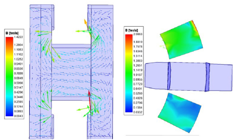
Figure 4: Stator and rotor magnetic vector distribution under misaligned positions.
IV. 3D FINITE ELEMENT CALCULATION OF MTF-DRSRM
Electromagnetic performance of the designed MTF-DRSRM is simulated using the finite element method and, during the simulation and analysis, the effect of eddy currents in the core on the magnetic field is neglected. The core magnetic vector distributions in the stator and rotor at both aligned and unaligned positions were obtained under independent single-phase excitation, as shown in Figs. 4 and 5. In the aligned position, the average maximum magnetic density of the stator core is about 1.6 T.
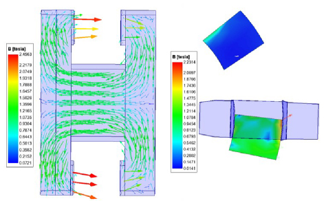
Figure 5: Stator and rotor magnetic vector distribution under aligned positions.
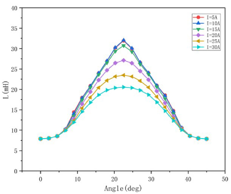
Figure 6: Inductance characteristic curve.
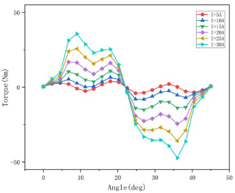
Figure 7: Moment angle characteristic curve.
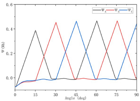
Figure 8: Characteristic curve of magnetic chain.
Figure 6 shows the inductance characteristic curve for rotor position angles from 0∘ to 45∘ and currents from 5 A to 30 A, where 0∘ is the rotor inter-polecenterline to the excitation pole centerline position, and 22.5∘ is the rotor pole centerline to the excitation pole centerline position. From Fig. 6, it can be seen that, for the three-phase 12/8-pole MTF-DRSRM, inductance increases with the increase of the rotor angle from 0∘ to 22.5∘ and decreases with the change of angle from 22.5∘ to 45∘. The inductance period of this motor is 45∘ and is symmetrical about 22.5∘.
Figure 7 shows the moment-angle characteristic curves for rotor position angle from 0∘ to 45∘ and current from 5 A to 30 A. In the range of rotor position angle 0∘ to 22.5∘, dL/d0, torque is positive. Torque increases with increase of current. In the range of rotor position angle 22.5∘ to 45∘, dL/d0, torque is negative, which is in line with theoretical derivation.
Figure 8 shows change of magnetic flux linked with three-phase curve for one operation cycle under angle control. When a phase of the motor conducts, the magnetic chain of the phase increases from 0. When the phase is disconnected, the magnetic chain reaches the maximum value, the winding renews the current, and the magnetic chain gradually decays to 0, and stays at 0 until the next cycle when the phase re-conducts. Figure 9 shows the three-phase rotating potential variation curve corresponding to the magnetic chain shown in Fig. 8.
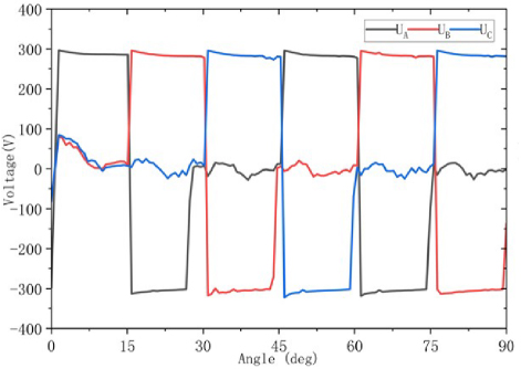
Figure 9: Electric potential waveform.
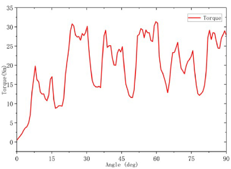
Figure 10: Torque graph.
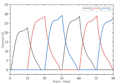
Figure 11: Three-phase current waveforms.
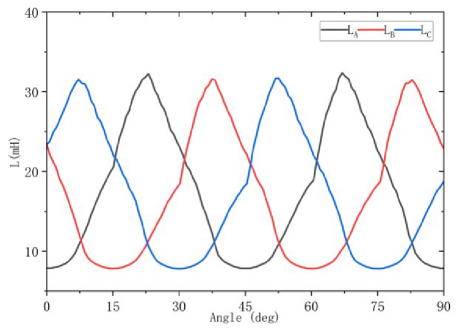
Figure 12: Three-phase inductance waveforms.
The MTF-DRSRM is stabilized by angular position control (APC) to measure the dynamic performance of the motor under rated operating conditions. Figures 10, 11, and 12 show the torque, three-phase current, and inductance curves of the motor at the rated speed of 1500 r/min. Figure 10 shows the instantaneous synthetic torque waveforms measured by simulation, with the maximum torque of 32.12 N-m, the minimum torque of 13.65 N-m, the average torque of 22.6 N-m, and the torque fluctuation coefficient of about 40.86%. From Fig. 11, it can be seen that the phase current waveform and the corresponding phase potential waveform under APC control are ideal.
V. CONCLUSION
This paper proposes a novel dual-rotor transverse-flux switched reluctance machine that synthetically integrates the magnetic circuit topology of transverse flux machines with modular stator-rotor construction. The motor demonstrates enhanced slot fill factor and flexible distributed winding configurations through axially aligned stator slots. Its modular assembly architecture combined with near-net shape manufacturing processes significantly reduces prototyping complexity and per-unit production costs while achieving high locked-rotor torque density characteristics that make it particularly suitable for direct-drive electric vehicle powertrains. The motor design parameters are analyzed by simulation to verify the correctness of the motor design method. The simulation shows that the MTF-DRSRM has a large output torque as well as low torque pulsation and stator copper consumption. The motor meets the initial design requirements, verifies the effectiveness of the MSRTFM design method proposed in this paper, and provides a theoretical basis for further optimization of the MSRTFM.
ACKNOWLEDGMENT
This work is supported by the Jiangsu Science and Technology Plan Special Fund (Innovation Support Plan International Science and Technology Cooperation/ Hong Kong Macao Taiwan Science and Technology Cooperation) Project (BZ2022014), and Jiangsu Provincial Market Supervision Administration Science and Technology Plan Project (KJ2025017),Shenzhen Basic Research Special (Natural Science Foundation) Key Project (JCYJ20220818100000001), 2022 China-CEEC University Joint Education Program (2022200), 2023 China-CEEC University Joint Education Program (2023304).
REFERENCES
[1] X. Sun, N. Wang, M. Yao, and G. Lei, “Position sensorless control of switched reluctance motors based on angle adjustment using nonlinear inductance and flux model,” IEEE Transactions on Industrial Electronics, vol. 71, no. 12, pp. 15467-15477, 2024.
[2] S. Xu, H. Chen, L. Tao, P. Wang, R. Nie, and J. Si, “Development of an even-phase switched reluctance motor drive for torque performance improvement,” IEEE Transactions on Energy Conversion, vol. 39, no. 4, pp. 2439-2452, 2024.
[3] X. Li, F. Liu, W. Jiang, H. Jin, M. Li, and Q. Wang, “Design and control of a transverse flux linear switched reluctance machine for rail transit application,” IEEE Access, vol. 10, pp. 43175-43186, 2022.
[4] H. Chen, R. Nie, and X. Li, “A transverse-flux single-phase tubular switched reluctance linear machine with 4 poles,” IEEE Transactions on Applied Superconductivity, vol. 31, no. 8, pp. 1-4, 2021.
[5] R. De Croo and F. De Belie, “Operating principle and characterisation of a novel contra-rotating dual-rotor switched reluctance machine,” IEEE Transactions on Industry Applications, vol. 60, no. 5, pp. 6775-6786, 2024.
[6] N. Prasad and M. Bukya, “New transverse linear switched reluctance motor design and analysis for transit uses,” Cogent Engineering, vol. 11, no. 1, pp. 1-8, 2024.
[7] H. Chen, R. Nie, W. Zhao, and J. Liu, “A novel three-phase tubular switched reluctance linear machine with transverse-flux path,” IEEE Transactions on Applied Superconductivity, vol. 30, no. 4, pp. 1-6, 2020.
[8] V. Mirzaei and M. Mirsalim, “A 24/28-pole hybrid reluctance motor with U-core stator,” in 2023 14th Power Electronics, Drive Systems, and Technologies Conference (PEDSTC), pp. 1-5, 2023.
[9] M. di Benedetto, A. Lidozzi, L. Solero, F. Crescimbini, P. J. Grbović, and M. Luna, “High-performance 3-phase 5-level e-type multilevel–multicell converters for microgrids,” Energies, vol. 14, no. 4, p. 843, 2021.
[10] H. Wang, Y. Xue, J. Du, and H. Li, “Design and evaluation of modular stator hybrid-excitation switched reluctance motor for torque performance improvement,” IEEE Transactions on Industrial Electronics, vol. 71, no. 10, pp. 12814-12823, 2024.
[11] S. Xu, H. Zeng, X. Jiang, G. Qi, and G. Han, “Reliability evaluation of dual stator switched reluctance motor system based on enhanced reliability model,” IEEE Transactions on Industry Applications, vol. 60, no. 6, pp. 8785-8796, 2024.
[12] M. Aydemir, “An innovative and non-intrusive Hall effect sensor-based rotor position detection system for external rotor switched reluctance motor,” Electrical Engineering, vol. 106, no. 1, pp. 1009-1019, 2024.
[13] X. Yao, H. He, J. Wang, Q. Guan, and R. Gao, “An online torque sharing function method based on region division for reducing torque ripple and copper losses of switched reluctance motors,” IEEE Journal of Emerging and Selected Topics in Power Electronics, vol. 12, no. 5, pp. 4825-4837, Oct. 2024.
[14] W. Libiao, K. T. Lionel, C. Ping, and Y. Lianghui, “Parameter identification of nonlinear flux-linkage model for switched reluctance motor based on chaotic diagonal recurrent neural network,” Journal of Engineering Science & Technology, vol. 17, no. 2, pp. 157-164, 2024.
BIOGRAPHIES

Hemiao Liu received the B.S. degree in electrical and information engineering from Beihua University, Jilin, China, in 2022. Since 2022, he has been pursuing a Ph.D. degree in electrical engineering from China University of Mining and Technology, Xuzhou. His current research interests include power electronics, electric vehicles, electric traction, wireless charging, and motor drives.

Xing Wang received the B.S. and M.S. degrees from China University of Mining and Technology, Xuzhou Jiangsu, China, in 1996. In 2007, she became an Associate Professor with China University of Mining and Technology, Xuzhou. She is a holder of four US Patents, nine Australian Patents, two Canadian Patents, four Russian Patents, 12 Chinese Invention Patents, three Chinese Utility Model Patents, and has authored 15 papers.

Hao Chen received the B.S. and Ph.D. degrees in electrical engineering from the Department of Automatic Control, Nanjing University of Aeronautics and Astronautics, Nanjing, China, in 1991 and 1996, respectively. He has been a professor at the School of Electrical and Power Engineering, China University of Mining and Technology, Xuzhou, since 2001. From 2002 to 2003, he was a Visiting Professor with Kyung sung University, Busan, South Korea. Since 2008, he has been an Adjunct Professor with the University of Western Australia, Perth, WA, Australia. He has authored one book and more than 200 articles. He holds 15 U.S. patents, 23 Australian patents, one Danish patent, seven Canadian patents, three South African patents, 10 Russian patents, 66 Chinese invention patents, and six Chinese utility model patents. His current research interests include motor control, linear launcher, electric vehicles, electric traction, servo drives, and wind power generator control. Chen was a recipient of the Prize of Science and Technology of Chinese Youth and the Prize of the Fok Ying Tong Education Foundation for Youth Teachers in 2004. He was awarded the First Prize in the Science and Technology Advanced of Province and Ministry once, the Second Prize in the Science and Technology Advanced of Province and Ministry nine times, and the Third Prize in the Science and Technology Advanced of Province and Ministry 14 times. He became the Chinese New Century Hundred-Thousand Ten-Thousand Talents Engineering National Talent in 2007 and won the Government Especial Allowance of People’s Republic of China State Department in 2006.

Jun Bao was born in August 1971. He is a Full Senior Engineer, currently serving as the director of Wuxi Institute of Inspection, Testing and Certification. His primary research areas include inspection and testing technologies for new energy vehicles, as well as metrological test technologies.

Haidong Yan was born in May 1982. He has a master’s degree in System Analysis and Integration from Nanjing University of Information Science & Technology, Nanjing, China. He is a Senior Engineer currently serving as the deputy director of Wuxi Institute of Inspection, Testing and Certification. His research direction mainly focuses on electromagnetic metrology, new energy vehicle specialized metrology and testing technology.

Guanjun Wang was born in September 1986. He has a master’s degree in Electronic and Communication Engineering from China University of Mining and Technology, Xuzhou, China. He is a Senior Engineer, currently serving as the Director of Electrical and Information M&R Department of Wuxi Institute of Inspection, Testing, and Certification. His research direction mainly focuses on electromagnetic metrology, new energy vehicle specialized metrology and testing technology.

Yassen Gorbounov received the B.S., M.S., and Ph.D. degrees from the Sofia University of Technology, Sofia, Republic of Bulgaria, in 2002, 2004, and 2013, respectively. Since 2017, he has been working as an Associate Professor with the Sofia University of Technology. His current research interests include power electronics and the mining industry.
ACES JOURNAL, Vol. 40, No. 9, 863–871
doi: 10.13052/2024.ACES.J.400907
© 2025 River Publishers