Design of Integrated Polygonal UWB MIMO Antenna With EBG Structure Based on Characteristic Mode Analysis
Fukuan Zhang, Zhonggen Wang, Wenyan Nie, Ming Yang, and Chenlu Li
1School of Electrical and Information Engineering
Anhui University of Science and Technology, Huainan 232001, China
2023200725@aust.edu.cn, zgwang@ahu.edu.cn
2School of Mechanical and Electrical Engineering
Huainan Normal University, Huainan 232001, China
wynie5240@163.com
3School of Electrical and Communications Engineering
West Anhui University, Lu’an 237012, China
myang@ahu.edu.cn
4School Electrical and Information Engineering
Hefei Normal University, Hefei 230061, China
chenluli@hfnu.edu.cn
Submitted On: December 24, 2024; Accepted On: April 29, 2025
ABSTRACT
This paper presents an analytical design of an integrated polygonal ultra-wideband (UWB) MIMO antenna, featuring a stepped electromagnetic band gap (EBG) integrated with a T-shaped stepped stub and utilizing characteristic mode analysis (CMA). The overall size of the antenna is 27220.8 mm. It comprises two symmetric octagonal radiating units, a T-shaped stepped floor, and an EBG structure positioned between the two radiating units. By analyzing the current and electric field distributions of the antenna’s characteristic modes, the feed point is identified at the rectangular microstrip line of the radiating unit, ensuring the simultaneous excitation of the antenna’s eight characteristic modes to achieve ultra-broadband characteristics. Meanwhile, the characteristic mode theory offers clear physical insights into antenna optimization. The bandwidth is improved by etching three positive T-slots on the floor. In comparison, the antenna isolation is enhanced by employing the EBG structure to suppress coupling currents and etching two inverted T-slots to modify the current path. Simulation and measurement results show that the antenna covers the 3.06-14 GHz band with isolation exceeding 20 dB. The antenna exhibits excellent radiation performance and a low envelope correlation coefficient (ECC).
Index Terms: Characteristic mode theory, EBG, MIMO antenna, T-slot, UWB antenna.
I. INTRODUCTION
With the emergence of 5G communication technology, the demand for antennas capable of supporting high-capacity data transmission has increased significantly [1]. Ultra-wideband (UWB) MIMO antennas have emerged as a key solution in wireless communication systems to meet this demand. Combining UWB and MIMO techniques offers enhanced bandwidth and higher data transmission rates while mitigating multipath fading effects and improving system capacity [2]. Consequently, UWB MIMO antennas find applications in radar detection, wireless data transmission, and medical monitoring systems.
For UWB MIMO antennas designed for portable devices, the primary focus is key characteristics such as compact size, bandwidth, and isolation. Continuous research on UWB MIMO antennas has yielded several approaches to enhance bandwidth and isolation [3–12]. The primary methods for achieving UWB characteristics include tapered geometries [13], resonant structures [14], and slot configurations [15]. To address the coupling issues caused by near-field radiation and current flow, common methods to improve isolation include electromagnetic band gap (EBG) structure [16], T-shaped stubs [17], and defective ground structures [18]. Reference [3] describes an antenna that comprises four monopole units and a sector isolation structure, featuring U-shaped patch elements and a defective rectangular ground plane. One of the sector decoupling structures efficiently suppresses coupling currents, thereby enhancing isolation. The antenna achieves a 2-11.08 GHz bandwidth while maintaining isolation exceeding 15 dB across the operational bandwidth. Reference [13] proposes a square slot antenna incorporating stepped transmission line loading, enabling resonance at multiple frequencies to achieve a UWB response spanning 2.1-11.5 GHz. Reference [14] introduces a metal slot array antenna employing a hybrid resonant structure. Through strategic arrangement and modification of the cavity and radiating slots, five resonant frequency points are simultaneously excited and tuned to the operating band, resulting in a bandwidth extension of 31%. Reference [15] proposes a UWB cross-tapered slot antenna on the ground plane, integrating millimeter-wave feed networks into its four 14 dipole arrays embedded in the cross-tapered arms. Due to the UWB characteristics of the slot antenna, it effectively covers most communication bands below 6 GHz. The antenna described in reference [16] incorporates a 23 EBG array between two electromagnetically coupled radiating patches to suppress surface wave coupling, with coupling further mitigated by a hairpin DGS on the ground plane. Compared to the original MIMO antenna, the EBG results in an average isolation enhancement of 13.9 dB in the 5G band, and the DGS provides a maximum isolation enhancement of 47.7 dB at 27.94 GHz. Reference [17] details a T-shaped grounding stub positioned between two radiating patches on the ground plane to suppress mutual coupling between MIMO elements and achieve an impedance bandwidth of 3.3-6 GHz with isolation exceeding 18 dB. Finally, the antenna in reference [18] leverages parasitic strips and defective ground structures to deliver wide bandwidth and enhanced isolation. It supports the n77/n78/n79 bands for 5G New Radio as well as the 5 GHz band for wireless local area networks, with isolation between any two ports greaterthan 15 dB.
All of the above techniques apply to the design of UWB MIMO antennas. However, achieving good operating bandwidth and high isolation—particularly in the low-frequency region of UWB—remains challenging, as these designs often rely on trial-and-error methods without detailed physical insights or theoretical guidance. In this context, characteristic mode analysis (CMA) offers purposeful optimization for antenna design and provides clear physical insights to enhance UWB MIMO antenna performance [19–32].
The ground MIMO antenna proposed in reference [20] leverages CMA to identify and excite three orthogonal modes (TM10, TM01, and TM20), incorporating a double-slot structure and an I-shaped patch into the coupling paths to enable simultaneous triple-band operation with high isolation. Reference [21] introduces a UWB antenna featuring dual-band trapping characteristics validated through CMA. The dual-trap band is achieved by embedding an L-shaped short interceptor into a trap rectangular patch, and the two trap bands are confirmed via CMA analysis of modal significance (MS) and characteristic angle (CA). Reference [25] employed CMA to modify the antenna shape to simultaneously excite multiple broadband modes through the feed slot, significantly enhancing bandwidth. The four-port antenna in reference [26] was entirely designed using CMA, covering a bandwidth of 2.8-11.4 GHz and achieving isolation exceeding 26 dB across its operational bandwidth.
In summary, this paper presents a novel dual-port UWB MIMO antenna structure consisting of two symmetric octagonal radiating units, a stepped EBG structure, and a T-shaped stepped stub, which enhances bandwidth and isolation through five T-shaped slots etched on the stepped stub and the integration of the stepped EBG structure. The proposed antenna achieves an operating bandwidth of 3.06-14 GHz, covering the entire UWB spectrum, with isolation exceeding 20 dB across the operating bandwidth while demonstrating excellent radiation and diversity performance. Additionally, the antenna evolution design is conducted using CMA. By analyzing the current and electric field distributions of the characteristic modes of antenna, the antenna feed point is located at the rectangular microstrip line of the radiating unit, ensuring simultaneous excitation of the eight characteristic modes of antenna to achieve ultra-broadband characteristics.
II. ANTENNA DESIGN
A. Antenna structure
In this paper, CST Studio suite is used to simulate the antenna. The antenna structure proposed in this paper is illustrated in Fig. 1. The antenna is printed on an FR4 dielectric substrate, featuring total dimensions of 27220.8 mm, a relative dielectric constant of 4.4, and a loss tangent of 0.02. Two integrated octagonal radiating units are fed by a microstrip line. The top and bottom rectangular patches connecting the inner and outer octagons are 1.1250.5 mm, while the left and right rectangular patches measure 0.8750.5 mm. Between these units, two cells form a stepped EBG, separated by a distance of 0.15 mm and connected by a rectangular patch with a width of 0.5 mm. A T-shaped stepped stub on the bottom surface of the substrate is connected via a cylinder with a radius of 0.5 mm. Each unit has a border width of 0.5 mm, and the internal rhombus patch is linked to the border through a 0.5 mm square patch. Additionally, five T-slots are etched on the T-stepped stub to extend the bandwidth and improve the isolation. Table 1 lists the antenna’s parametric dimensions.
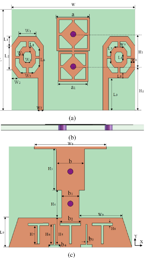
Figure 1: Proposed UWB MIMO antenna structure: (a) top view, (b) side view, and (c) bottom view.
Table 1: Parameter dimensions of the antenna
| Parameters | W | L | W | L | W | L |
| Value(mm) | 27 | 22 | 4 | 2 | 1.5 | 5 |
| Parameters | W | L | W | L | W | L |
| Value(mm) | 0.875 | 7 | 1 | 1.25 | 3 | 1.125 |
| Parameters | W | L | W | L | W | L |
| Value(mm) | 0.875 | 3.75 | 2 | 2.5 | 9.5 | 6.4 |
| Parameters | W | W | H | b | b | b |
| Value(mm) | 15.8 | 1.2 | 0.5 | 6.2 | 3.8 | 4.5 |
| Parameters | L | b | b | a | a | H |
| Value(mm) | 1.125 | 0.5 | 2.5 | 7.2 | 6.5 | 7 |
| Parameters | H | H | H | H | H | H |
| Value(mm) | 9.5 | 9 | 6 | 5.8 | 4.4 | 4 |
B. Antenna evolution and analysis
Figure 2 illustrates the evolution of the antenna structure, while Fig. 3 presents the corresponding simulated S-parameter curves. Figure 4 presents the MS and CA of antenna 1, while Fig. 5 illustrates the current distribution at resonance points for its characteristic modes. MS represents the extent to which each mode resonates within a specific frequency range. An MS value closer to 1 indicates that the mode can be more effectively excited under appropriate feeding conditions, whereas an MS value below 0.707 indicates a low likelihood of resonance. Similarly, CA represents the antenna’s resonance performance, and a CA value closer to 180 signifies a higher probability of mode resonance.
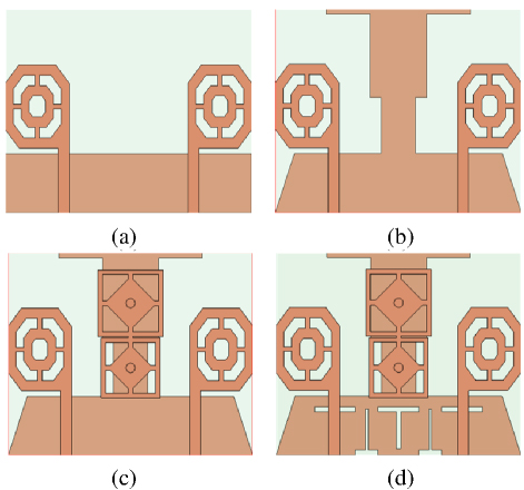
Figure 2: Design development of antenna structure: (a) antenna 1, (b) antenna 2, (c) antenna 3, and (d) antenna 4.
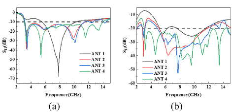
Figure 3: Simulated S-parameter plot of the antenna: (a) S11 and (b) S12.
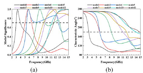
Figure 4: Results of mode analysis of antenna 1: (a) MS and (b) CA.
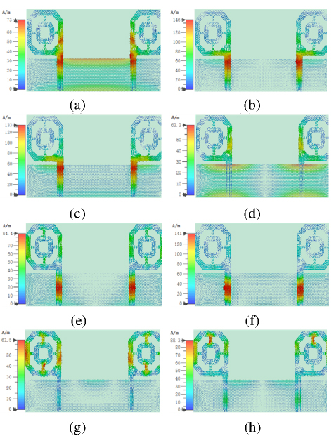
Figure 5: Mode current distribution of antenna 1: (a) mode 1 at 3.28 GHz, (b) mode 2 at 5.73 GHz, (c) mode 4 at 5.71 GHz, (d) mode 5 at 8.40 GHz, (e) mode 7 at 11.02 GHz, (f) mode 9 at 11.86 GHz, (g) mode 10 at 13.97 GHz, and (h) mode 12 at 14.77 GHz.
An analysis of Fig. 4 indicates that, among the 12 characteristic modes, modes 1, 2, 4, 5, 7, 9, 10, and 12 are theoretically excited under appropriate feeding conditions. However, an analysis of Fig. 5 reveals that the currents of mode 5 are primarily distributed on the floor, while the currents of modes 10 and 12 are mainly concentrated on the outer octagon of the radiating patch. These mode currents are weak, located far from the feed ports, cannot be effectively excited, and therefore do not contribute to the bandwidth. The currents of modes 1, 2, 4, 7, and 9 are primarily concentrated in the rectangular feeder of the radiating patch and are effectively excited. However, the bandwidth of mode 4 overlaps with that of modes 2, 7, and 9 and, thus, the combined bandwidth they provide fails to meet the UWB requirements. The bandwidth of antenna 1, as shown in Fig. 3 (a), is in the range 5.52-10.3 GHz, indicating that the structure is insufficient to satisfy the UWB requirement. Therefore, the structure of antenna 1 was improved and optimized, as depicted in Fig. 2 (b).
To enable more distinct excitable patterns and ensure the combined bandwidth meets the UWB requirement, antenna 2 modifies the rectangular floor of antenna 1 into a stepped T-shaped floor, as shown in Fig. 2 (b). Figures 6 and 7 present the characteristic modes, CAs, and mode current distribution of antenna 2. Compared to antenna 1, antenna 2 exhibits changes in the characteristic mode shapes and effective bandwidth. Specifically, the resonant frequency of mode 10 shifts from a high to a low frequency, and the effective bandwidth is reduced. Meanwhile, the resonant frequencies of modes 1, 2, and 4 shift slightly toward higher frequencies, with minor changes in shape and increased bandwidth. The resonant frequency of mode 5 shifts to a lower frequency by 0.48 GHz, while mode 7 shifts by 3.45 GHz to a lower frequency. Mode 9 has a resonant frequency of 0.86 GHz, and mode 12 shifts by 2.74 GHz toward a lower frequency. The combined bandwidths of these modes fully cover the UWB ranges from 3.1 to 10.6 GHz. As shown in Fig. 7, the current of mode 7 primarily distributes at the top of the floor, far from the feed point, and cannot be excited. However, the other modes have strong currents at the feed point and can be excited, collectively contributing to the UWB requirement. The S-parameters of antenna 2, as shown in Fig. 3, indicate that antenna 2 achieves a UWB band of 3.12-11.6 GHz compared to antenna 1. However, the isolation in this band is greater than 12.6 dB, failing to meet the isolation requirements for MIMO antennas. Therefore, the structure of antenna 2 was further refined.
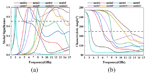
Figure 6: The results of mode analysis of antenna 2: (a) MS and (b) CA.
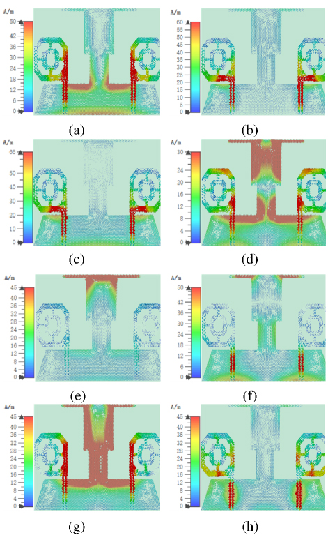
Figure 7: Mode current distribution of antenna 2: (a) mode 1 at 3.38 GHz, (b) mode 2 at 5.96 GHz, (c) mode 4 at 6.03 GHz, (d) mode 5 at 7.92 GHz, (e) mode 7 at 7.57 GHz, (f) mode 9 at 10.61 GHz, (g) mode 10 at 2.93 GHz, and (h) mode 12 at 12.03 GHz.
To enhance antenna isolation, antenna 3 incorporates an EBG structure derived from antenna 2, as shown in Fig. 2 (c). The metal cylinder in the EBG structure links the upper surface of the floor to the antenna structure, focusing floor currents onto the rectangular patch within the EBG structure. This configuration effectively suppresses surface and space wave propagation, reduces mutual coupling between antenna radiating units, and enhances antenna isolation. Introduction of the EBG structure modifies the overall antenna structure, altering its characteristic modes and currents, as illustrated in Figs. 8 and 9.
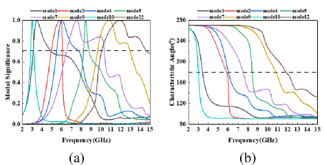
Figure 8: Results of mode analysis of antenna 3: (a) MS and (b) CA.
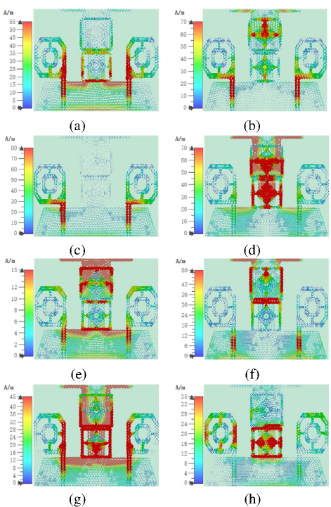
Figure 9: Mode current distribution of antenna 3: (a) mode 1 at 3.42 GHz, (b) mode 2 at 5.84 GHz, (c) mode 4 at 6.02 GHz, (d) mode 5 at 8.41 GHz, (e) mode 7 at 7.50 GHz, (f) mode 9 at 10.81 GHz, (g) mode 10 at 3.00 GHz, and (h) mode 12 at 12.03 GHz.
Figure 8 illustrates the characteristic modes and angles of the antenna, while Fig. 9 depicts the characteristic current distribution at resonance points. A comparison of Figs. 9 and 7 reveals that the EBG structure enables mode 7, previously unexcited in antenna 2, to be excited in antenna 3, thereby broadening the bandwidth. Compared to antenna 2, the resonance frequencies of characteristic modes of antenna 3 shift by approximately 0.2 GHz toward either lower or higher frequencies with minimal variation, resulting in an effective bandwidth meeting the UWB requirement. Figure 3 shows that antenna 3 achieves a bandwidth of 3.16-11.4 GHz, with isolation exceeding 14.51 dB across this range. Compared to antenna 2, the EBG structure reduces low-frequency isolation by 1.91 dB. Although this remains below the MIMO antenna isolation requirement of 17 dB, the bandwidth is slightly reduced, failing to fully cover 3.1-10.6 GHz. To address these issues, five T-slots are etched on the floor of antenna 3 to broaden the bandwidth and improve isolation, resulting in the final antenna structure shown in Fig. 2 (d).
Figure 3 demonstrates that the etched T-slot enables the antenna to cover the band range of 3.06-14 GHz, fully complying with UWB requirements and achieving isolation greater than 20 dB. Three positive T-slots are responsible for bandwidth enhancement, while two inverted T-slots improve antenna isolation. Figures 10 and 11 illustrate that etching of the T-slots modifies the antenna structure and influences distribution of its characteristic modes and currents. As shown in Fig. 11, the current distribution of characteristic modes of antenna 4 is more concentrated near the feed point, enabling excitation. Figure 10 shows that the combined bandwidth contributed by these modes completely covers 3-14 GHz, which aligns with Fig. 3 (a), confirming that antenna 4 covers the band range 3.06-14 GHz.
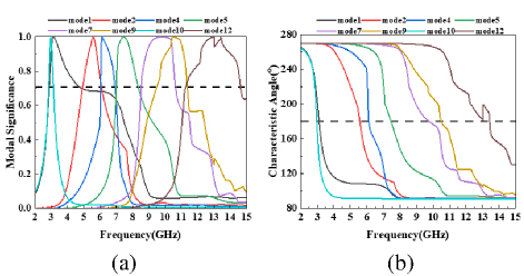
Figure 10: Results of mode analysis of antenna 4: (a) MS and (b) CA.
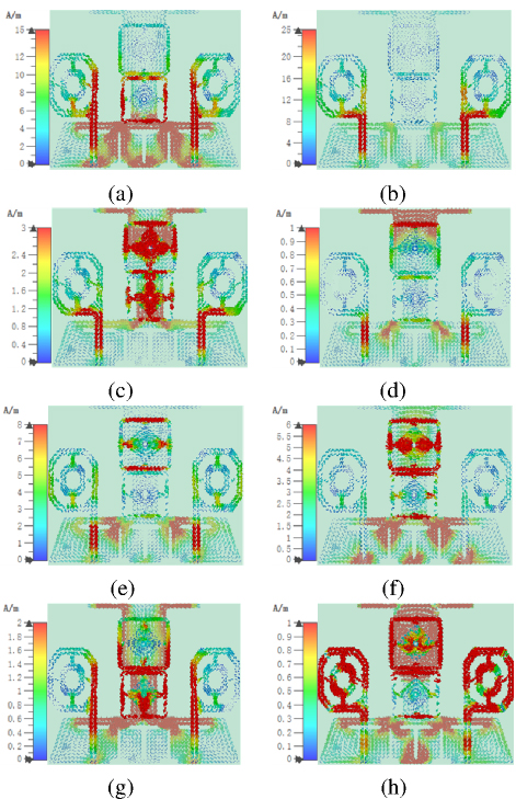
Figure 11: Mode current distribution of antenna 4: (a) mode 1 at 3.10 GHz, (b) mode 2 at 5.56 GHz, (c) mode 4 at 6.10 GHz, (d) mode 5 at 7.45 GHz, (e) mode 7 at 9.75 GHz, (f) mode 9 at 10.48 GHz, (g) mode 10 at 2.97 GHz, and (h) mode 12 at 13.41 GHz.
C. Antenna parameter analysis
A systematic study was conducted to analyze the impact of various antenna parameters on its performance. The objective was to assess how antenna parameters influence bandwidth and isolation. Four parameters were studied, namely b and H for positive T-slots and b and H for inverted T-slots. The first three parameters were selected due to their influence on both bandwidth and isolation, while the last parameter was chosen for its significant role in enhancing isolation.
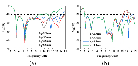
Figure 12: Effect of different b lengths on antenna S-parameters: (a) S11 and (b) S12.
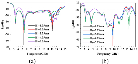
Figure 13: Effect of different H lengths on antenna S-parameters: (a) S11 and (b) S12.
The analysis process involves varying one parameter while keeping the others constant. The parameter analysis results are presented in Fig. 12. Figure 12 shows that b significantly impacts the high-frequency region of the S-parameters, as increasing b worsens the high-frequency matching of S11 and reduces coverage while improving S12 performance. Thus, b is set to 4.5 mm. Figure 13 indicates that H primarily influences the high-frequency resonance point of S11. As H increases, the high-frequency resonance point of S11 shifts towards the mid-frequency region and its depth decreases, while the opposite trend is observed for S12. When H increases from 4.25 mm to 5.25 mm, the low-frequency matching of the S-parameters degrades. Thus, H is set to4.25 mm.
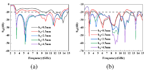
Figure 14: Effect of different b lengths on antenna S-parameters: (a) S11 and (b) S12.
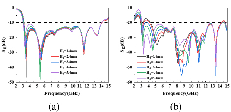
Figure 15: The effect of different H lengths on antenna S-parameters: (a) S11 and (b) S12.
Figure 14 shows that, as b increases from 1.5 mm to 2.5 mm, the antenna transitions from impedance mismatch to a matched state. Subsequently, the high-frequency resonance point of S11 shifts upward, and the 5.4 GHz resonance point shifts leftward with increasing length. Thus, b is set to 2.5 mm. Figure 15 demonstrates that H significantly influences S12. As H increases, bandwidth remains constant while isolation improves progressively. Considering the resonance depth of S11, H is set to 4.4 mm.
III. RESULTS AND DISCUSSION
A. S-parameters
To test the actual performance of the antenna, the antenna model is processed as shown in Fig. 16 (b). The antenna S-parameters were measured using an Agilent N5235A vector network analyzer, and the antenna microwave darkroom measurement environment is shown in Fig. 16 (a). Figure 17 shows the simulated and measured S-parameters of the antenna. From Fig. 17, it can be seen that the antenna covers the band 3.06-14 GHz and contains the UWB band. In addition, the S12 parameter of the antenna stays below -20 dB in the UWB band, showing good isolation. Please note that the difference between the simulated and measured results may be due to manufacturing processes and soldering errors. However, in general, their results match very well, and the overall performance of the antenna remainsconsistent.
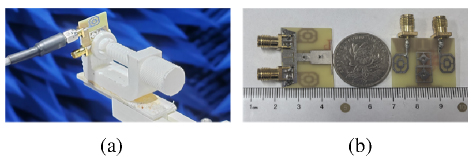
Figure 16: Proposed antenna: (a) S-parameters measurement environment and (b) fabricated prototype.
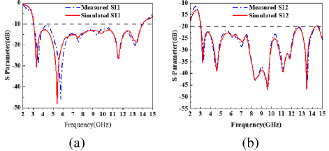
Figure 17: MIMO antenna simulated and measured S-parameters: (a) S11 and (b) S12.
B. Radiation properties
Figure 18 depicts the two-dimensional radiation patterns of the antenna in the E-plane and H-plane at 3.34 GHz, 5.4 GHz, 11.57 GHz, and 13.37 GHz. From Fig. 18, it can be seen that the shape of the radiation pattern in the E-plane and H-plane at 3.34 GHz and 11.57 GHz approximates a circle and exhibits good omnidirectional radiation characteristics. At the resonance frequency of 5.4 GHz, the radiation pattern of the E-plane is circular and that of the H-plane is in the shape of a cashew nut. The maximum radiation direction of the H-plane is in the range 150-180 () and 120-180 (), whereas that of the E-plane is omnidirectional, which indicates better radiation characteristics. At the resonance frequency of 13.37 GHz, the radiation pattern in the E-plane is concave inward in the 90 () azimuth, and the radiation pattern in the H-plane is concave inward in the 120-150 () azimuth. Both show a circular shape in the rest of the directions, which almost achieves an omnidirectional radiation characteristic.
Figure 19 shows the radiation efficiency and peak gain of the antenna over the operating band. The peak gain of the antenna can reach a maximum of 3.42 dBi. In addition, the antenna has a high radiation efficiency of more than 66% over the entire operating band.
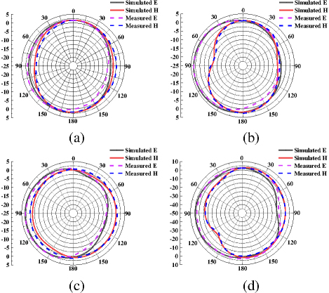
Figure 18: Simulated and measured radiation patterns at (a) 3.34 GHz, (b) 5.4 GHz, (c) 11.57 GHz, and (d) 13.37 GHz.
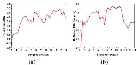
Figure 19: (a) Peak realized gain and (b) radiation efficiency of the proposed antenna.
C. MIMO antenna performance
The diversity and mutual coupling characteristics of a MIMO antenna can be measured by its envelope correlation coefficient (ECC) [33]. ECC quantifies the correlation between received signal amplitudes of different antenna elements, with lower ECC values indicating better independence between the antenna elements, as calculated in equation (1). Diversity gain (DG) is a key metric indicating signal amplification or attenuation in MIMO systems and is determined by equation (2). Generally, the ECC of a MIMO antenna is expected to be lower than 0.5, indicating compliance with S-parameters (dB), radiation efficiency (%), and peak gain (dBi) requirements. Furthermore, a DG value closer to 10 suggests better MIMO antenna performance. As shown in Fig. 20, the ECC of this antenna is below 0.005, and the DG approaches 10, demonstrating that the antenna meets the communication requirements within the 3.06-14 GHz band.
| (1) |
| (2) |
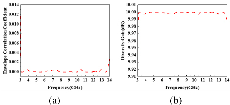
Figure 20: (a) ECC and (b) DG of the proposed antenna.
The total effective reflection coefficient (TARC) is a critical parameter for assessing the efficiency of a MIMO antenna system. To achieve low reflection loss, stable phase performance, and reliable signal transmission in the MIMO antenna system, the TARC should be less than -10 dB. The calculation formula for TARC is:
| (3) |
Figure 21 illustrates the TARC performance of the proposed antenna. As shown in Fig. 21, the TARC is less than -32 dB within the frequency band of 3.06-14 GHz, indicating minimal coupling within the MIMO system. This ensures channel independence at both transceiver and receiver ends while effectively leveraging the multipath effect to enhance system capacity.
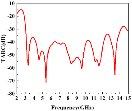
Figure 21: TARC of the proposed antenna.
Table 2 presents a performance comparison between the proposed antenna and several existing designs in terms of size, bandwidth, isolation, and ECC. From Table 2, it can be observed that the antenna offers larger bandwidth and lower ECC than [2] while providing a smaller size, wider bandwidth, and lower ECC than [6, 11]. These advantages indicate the superior diversity performance and space utilization of the antenna. It also achieves a smaller size and larger bandwidth than [8]. At the same time, it has the same isolation properties as [2, 6, 11, 8]. Compared to reference [26], the proposed antenna exhibits a smaller size and broader bandwidth coverage, while preserving similar isolation and ECC levels. In addition, our design demonstrates stronger isolation characteristics and enhanced diversity performance in the 3.0-11.0 GHz frequency range, compared to reference [27]. Compared to reference [30], the proposed antenna has a smaller size while maintaining comparable isolation characteristics, which substantially enhances space utilization without compromising the radiation characteristics. Additionally, the antenna demonstrates a smaller size, higher isolation, larger bandwidth, and superior diversity performance compared to [3, 5, 9, 10] and it enables the antenna to show enhanced isolation performance and superior space utilization without compromising the radiation characteristics. In conclusion, the proposed antenna offers notable advantages regarding size, bandwidth, isolation, and diversityperformance.
Table 2: Parameter dimensions of the antenna
| Parameters | W | L | W | L | W | L |
| Value(mm) | 27 | 22 | 4 | 2 | 1.5 | 5 |
| Parameters | W | L | W | L | W | L |
| Value(mm) | 0.875 | 7 | 1 | 1.25 | 3 | 1.125 |
| Parameters | W | L | W | L | W | L |
| Value(mm) | 0.875 | 3.75 | 2 | 2.5 | 9.5 | 6.4 |
| Parameters | W | W | H | b | b | b |
| Value(mm) | 15.8 | 1.2 | 0.5 | 6.2 | 3.8 | 4.5 |
| Parameters | L | b | b | a | a | H |
| Value(mm) | 1.125 | 0.5 | 2.5 | 7.2 | 6.5 | 7 |
| Parameters | H | H | H | H | H | H |
| Value(mm) | 9.5 | 9 | 6 | 5.8 | 4.4 | 4 |
IV. CONCLUSION
This paper analyzes and designs an integrated polygonal UWB MIMO antenna with an EBG structure based on characteristic mode theory for high isolation. In the process of antenna evolution, the antenna structure is optimized by analyzing its characteristic modes and characteristic current distribution to adjust the bandwidth and mode coverage, ensuring simultaneous excitation of the eight characteristic modes and achieving UWB characteristics. Characteristic mode theory provides detailed physical insights and guides antenna optimization, resulting in a design with two symmetric octagonal radiating units, a T-shaped stepped floor, and an EBG structure. Additionally, five T-slots on the floor redirect current flow, enhancing antenna isolation to over 20 dB. Simulated and measured results demonstrate a bandwidth of 3.06-14 GHz, covering UWB and supporting 5G, WiFi6E, and X-band applications. The antenna also features a compact structure, small size, high radiation efficiency, and low ECC. In summary, the antenna exhibits excellent performance, making it suitable for various wireless communication bands.
ACKNOWLEDGMENT
This work was supported in part by the Natural Science Research Project of Anhui Educational Committee under grant no. 2022AH051583, no. 2022AH052138, and no. 2023AH052650; in part by the Anhui Province Graduate Academic Innovation Project under grant no. 2023xscx074; in part by the Funding Project of Scientific Research Starting for the High-level Talents of West Anhui University under grant no. WGKQ2022009.
REFERENCES
[1] M. A. Chung, C. C. Hsu, M. C. Lee, and C. W. Lin, “Enhancing multi-band MIMO antenna stability for various electronic applications with human-body interaction consideration,” IEEE Access, vol. 11, pp. 129376-129398, 2023.
[2] W. Li, L. Wu, S. Li, X. Cao, and B. Yang, “Bandwidth enhancement and isolation improvement in compact UWB-MIMO antenna assisted by characteristic mode analysis,” IEEE Access, vol. 12, pp. 17152-17163, 2024.
[3] W. Ren, Z. G. Wang, M. Yang, J. Zhou, and W. Y. Nie, “Design of a simple four-port UWB-MIMO antenna based on a fan-shaped isolator,” Progress Electromagnetics Research M, vol. 126, pp. 117-126, 2024.
[4] S. Jayant, G. Srivastava, and S. Kumar, “Quad-port UWB MIMO footwear antenna for wearable applications,” IEEE Transactions on Antennas and Propagation, vol. 70, pp. 7905-7913, 2022.
[5] S. H. Kiani, H. S. Savci, M. E. Munir, A. Sedik, and H. Mostafa, “An ultra-wide band MIMO antenna system with enhanced isolation for microwave imaging applications,” Micromachines, vol. 14, p. 1732, 2023.
[6] S. Jayant and G. Srivastava, “Close-packed quad-element trip-band-notched UWB MIMO antenna with upgrading capability,” IEEE Transactions on Antennas and Propagation, vol. 71, pp. 353-360, 2023.
[7] B. T. Ahmed, “High isolation compact UWB MIMO antennas,” Wireless Personal Communications, vol. 128, pp. 3003-3029, 2023.
[8] Y. Yao, Y. Shao, J. Zhang, and J. Zhang, “A transparent antenna using metal mesh for UWB MIMO applications,” IEEE Transactions on Antennas and Propagation, vol. 71, pp. 3836-3844, 2023.
[9] A. A. Khan, S. A. Naqvi, M. S. Khan, and B. Ijaz, “Quad port miniaturized MIMO antenna for UWB 11 GHz and 13 GHz frequency bands,” AEU-International Journal of Electronics and Communications, vol. 131, p. 153618, 2021.
[10] A. G. Alharbi, U. Rafique, S. Ullah, S. Khan, S. M. Abbas, E. M. Ali, M. Alibakhshikenari, and M. Dalarsson, “Novel MIMO antenna system for ultra-wideband applications,” Applied Sciences, vol. 12, p. 3684, 2022.
[11] M. Abdelghany, M. Fathy, A. Desai, and A. Ibrahim, “4-Port octagonal shaped MIMO antenna with low mutual coupling for UWB applications,” Computer Modeling in Engineering & Sciences, vol. 136, pp. 1999-2015, 2023.
[12] R. N. Tiwari, V. Kaim, P. Singh, T. Khan, and B. K. Kanaujia, “Semi-flexible diversified circularly polarized millimeter-wave MIMO antenna for wearable biotechnologies,” IEEE Transactions on Antennas and Propagation, vol. 71, pp. 3968-3982, 2023.
[13] P. M. Paul, K. Kandasamy, M. S. Sharawi, and B. Majumder, “Dispersion-engineered transmission line loaded slot antenna for UWB applications,” IEEE Antennas and Wireless Propagation Letters, vol. 18, pp. 323-327, 2019.
[14] L. Sang, J. Wang, Z. Liu, W. Wang, W. Huang, and H. Tu, “A UWB metal waveguide slot array antenna based on hybrid resonant structural components,” IEEE Antennas and Wireless Propagation Letters, vol. 22, pp. 923-927, 2023.
[15] Y. Cheng and Y. Dong, “Ultrawideband shared-aperture crossed tapered slot antenna for 5G applications,” IEEE Antennas and Wireless Propagation Letters, vol. 22, pp. 472-476, 2023.
[16] S. Dey, S. Dey, and S. K. Koul, “Isolation improvement of MIMO antenna using novel EBG and hair-pin shaped DGS at 5G millimeter wave band,” IEEE Access, vol. 9, pp. 162820-162834, 2021.
[17] M. S. Aung and T. T. Hla, “Two-port wideband MIMO antenna for sub-6 GHz 5G applications,” in IEEE Conference on Computer Applications (ICCA), Yangon, Myanmar, pp. 1-6, 2024.
[18] Y. Hei, J. He, and W. Li, “Wideband decoupled 8-element MIMO antenna for 5G mobile terminal applications,” IEEE Antennas and Wireless Propagation Letters, vol. 20, pp. 1448-1452, 2021.
[19] Z. G. Wang, R. You, M. Yang, J. Zhou, and M. Wang, “Design of a monopole antenna for WiFi-UWB based on characteristic mode theory,” Progress in Electromagnetics Research M, vol. 125, pp. 107-116, 2024.
[20] J. Su, S. Di, C. Yao, and X. Chen, “A compact high-isolation tri-band MIMO antenna based on characteristic mode analysis,” Progress in Electromagnetics Research M, vol. 129, pp. 1-10, 2024.
[21] S. Grandhi Venkata and S. R. K. Kalva, “UWB monopole antenna with dual notched bands verified by characteristic mode analysis (CMA),” Progress in Electromagnetics Research C, vol. 121, pp. 39-48, 2022.
[22] L. Qu, “Common-loop MIMO antenna design with decoupling inductors using characteristic mode analysis,” IEEE Antennas and Wireless Propagation Letters, vol. 22, pp. 3172-3176, 2023.
[23] N. W. Liu, B. B. Huang, and L. Zhu, “Isolation and bandwidth improvements of multimode single MPA with copolarized pattern using characteristic modes analysis,” IEEE Antennas and Wireless Propagation Letters, vol. 22, pp. 1356-1360,2023.
[24] J. Chen, M. Berg, K. Rasilainen, Z. Siddiqui, M. E. Leinonen, and A. Parssinen, “Broadband cross-slotted patch antenna for 5G millimeter-wave applications based on characteristic mode analysis,” IEEE Transactions on Antennas and Propagation, vol. 70, pp. 11277-11292, 2022.
[25] X. Wang, L. Guo, W. Zhou, and Q. Zhang, “A double-layer multimode metasurface antenna using characteristic mode analysis,” IEEE Antennas and Wireless Propagation Letters, vol. 23, pp. 3237-3241, 2024.
[26] A. C. Suresh and T. S. Reddy, “Experimental investigation of novel frock-shaped miniaturized 44 UWB MIMO antenna using characteristic mode analysis,” Progress in Electromagnetics Research B, vol. 101, pp. 45-61, 2023.
[27] Z. J. Tang, J. Zhan, B. Zhong, L. Cheng, and G. Zuo, “Design of a coplanar UWB-MIMO ground antenna based on the theory of characteristic modes,” Progress in Electromagnetics Research C, vol. 117, pp. 221-237, 2021.
[28] Y. Jia, J. Luo, X. Ren, G. Shi, and Y. Liu, “Design of low-RCS Vivaldi antenna based on characteristic mode analysis,” IEEE Antennas and Wireless Propagation Letters, vol. 23, pp. 1246-1250, 2024.
[29] T. L. Yang, X. Zhang, Q. S. Wu, and T. Yuan, “Miniaturized wideband circularly polarized triangular patch antennas based on characteristic mode analysis,” Applied Computational Electromagnetics Society (ACES) Journal, vol. 38, pp. 783-791, 2023.
[30] W. Y. Ren, Z. G. Wang, W. Y. Nie, W. D. Mu, C. L. Li, and M. Q. Wang, “A transparent ultra-wideband antenna fed by CPW based on characteristic mode theory,” Applied Computational Electromagnetics Society (ACES) Journal, vol. 39, pp. 987-998, 2024.
[31] S. Liu, L. Yang, and X. Wu, “A low-profile wideband circularly polarized metasurface antenna based on characteristic mode theory,” Applied Computational Electromagnetics Society (ACES) Journal, vol. 37, pp. 1110-1117, 2022.
[32] Z. Z. Wang, N. W. Liu, and L. Fang, “Low-profile dual-polarized filtering antenna with improved gain and impedance bandwidth using characteristic mode analysis,” Applied Computational Electromagnetics Society (ACES) Journal, vol. 38, pp. 767-773, 2023.
[33] Z. G. Wang, G. X. Song, W. Y Nie, M. Yang, C. L. Li, and M. Q. Wang, “A racket-like UWB MIMO antenna with high isolation,” Progress in Electromagnetics Research C, vol. 144, pp. 159-168,2024.
BIOGRAPHIES

Fukuan Zhang received the B.E. degree from Anhui University of Science and Technology in 2023. He is currently pursuing the M.S degree at Anhui University of Science and Technology. His current research interests include the theory and design of UWB MIMO antenna based on characteristic mode analysis.

Zhonggen Wang received the Ph.D. degree in electromagnetic field and microwave technique from the Anhui University of China (AHU), Hefei, P.R. China, in 2014. Since 2014, he has been with the School of Electrical and Information Engineering, Anhui University of Science and Technology. His research interests include computational electromagnetics, array antennas, and reflect arrays.

Wenyan Nie is a professor at Huainan Normal University. She received the B.S. and M.S degrees from Anhui University of Science and Technology in 2007 and 2012, respectively. Her research interests include computational electromagnetic methods, and antenna theory and design.

Ming Yang received the B.S. degree from Huaibei Normal University in 2005, and the M.S. and Ph.D. degrees in electromagnetic field and microwave technology from Anhui University, Hefei, China, in 2010 and 2019, respectively. He is currently the Deputy Director of the School of Electronics and Information Engineering, at West Anhui University, Lu’an, China. He is the author and co-author of about 20 scientific papers published in journals and presented at international conferences in the field of antenna design. His current research interests include MIMO antennas for hand-held devices, SIW antennas, base station antennas, multi-band antennas, millimeter wave antennas, and antenna array design.

Chenlu Li received the Ph.D. degree from Anhui University in 2017. She is currently working at Hefei Normal University. Her research interests include electromagnetic scattering analysis of targets and filtering antenna design.
ACES JOURNAL, Vol. 40, No. 5, 390–400
doi: 10.13052/2025.ACES.J.400502
© 2025 River Publishers