Design of Gravity Energy Storage Switched Reluctance Machine Based on Artificial Intelligence Optimization Algorithm
Wenju Yan, Xinzhu Sun, Jun Xin, Hao Chen, Yang Wang, Vuong Dang Quoc, and Thanh Nguyen Vu
1School of Electrical Engineering, China University of Mining and Technology
Xuzhou 221116, China
6288@cumt.edu.cn, ts23230199p31@cumt.edu.cn, ts23230161p31ld@cumt.edu.cn, hchen@cumt.edu.cn, ts23230200p31@cumt.edu.cn
2Shenzhen Research Institute, China University of Mining and Technology
Shenzhen 518057, China
3School of Electrical Engineering, Hanoi University of Science and Technology
Hanoi, Vietnam
vuong.dangquoc@hust.edu.vn, thanh.nguyenvu@hust.edu.vn
Submitted On: December 26, 2024; Accepted On: May 29, 2025
ABSTRACT
To address the operational characteristics of gravity energy storage systems, this paper proposes an optimized design method for a switched reluctance machine (SRM) suitable for a gravity energy storage system. A novel 12/8 salient stator tooth structure is introduced to enhance performance in both energy storage and power generation modes. Four key optimization objectives are defined: average torque and torque ripple in the energy storage state, as well as generation power and efficiency in the power generation state. The influence of structural parameters on these optimization objectives is systematically analyzed and a multi-objective optimization of the structural parameters is conducted by the Multi-Objective Grey Wolf Optimizer (MOGWO) algorithm. Finite element analysis (FEA) is performed to evaluate the electromagnetic characteristics of the optimized design. The results demonstrate that the proposed SRM achieves superior performance compared to the traditional 12/8 SRM, making it well-suited for gravity energy storage applications.
Index Terms: Gravity energy storage, motor and generator, multi-objective optimization, switched reluctance machine.
I. INTRODUCTION
Energy storage technology plays a pivotal role in the renewable energy sector, as it helps address the intermittency and instability of renewable energy sources while enhancing energy utilization efficiency. Compared to other energy storage methods, gravity energy storage offers significant advantages, including site flexibility, environmental friendliness, high storage capacity, long cycle life, zero self-discharge rate, deep discharge depth, fast response time, and high efficiency, making it a promising form of green energy storage. According to reports from international sources, the main configurations of gravity energy storage systems currently include piston-based gravity energy storage, mine shaft suspended gravity storage, tower crane-based concrete block energy storage, and mountain railway gravity energy storage [1–3]. Among these, mine shaft suspended gravity storage stands out for its technical advantage of repurposing abandoned resources while addressing energy supply-demand imbalances, offering broad application prospects.
The gravity energy storage motor is the core component responsible for the conversion of electrical energy and gravitational potential energy. In motoring or energy storage state, it stores gravitational potential energy and, in generating or the power generation state, it releases gravitational potential energy. Its performance directly determines the overall efficiency of the energy storage system. Compared to conventional industrial motors, energy storage motors face stricter technical requirements, such as high power and torque densities, maintaining high efficiency over a wide operating range, delivering high torque at low speeds, frequent heavy-load starts, high reliability, and excellent performance in both motoring and generating states. As a rare-earth-free motor technology [4–7], switched reluctance motors (SRMs) are particularly well-suited for applications with high-inertia operating conditions involving gravity energy storage systems. Since SRMs have the advantages of high starting torque, low starting current, the ability to handle frequent heavy-load starts, a broad high-efficiency range, and inherent structural reliability, this paper focuses on applying SRMs in gravity energy storage.
To improve the performance of conventional SRMs, researchers frequently optimize motor structures, materials, and geometric parameters [8–11]. Specifically, substantial progress has been made in enhancing SRMs through innovative designs of stator and rotor structures. A 6/4-pole three-phase SRM featuring uniquely skew-angle rotor poles combined with sinusoidal torque-sharing control was proposed and simulated in [12]. Prasad et al. [13] introduced a linear SRM tailored for high-speed transportation systems with dual teeth on each stator pole to enhance thrust and analyzed its force ripple reduction effectiveness with finite elements. Li et al. [14] developed an axial dual-rotor segmented SRM with a new rotor profile, where rotor segment geometry was optimized to boost performance. A hollow-tooth rotor structure for a 6/2-pole SRM was designed in [15], effectively extending its acceleration range. Ma et al. [16] improved SRM vibration and noise issues by introducing rectangular slots at the stator tooth tips and optimizing the slot geometry to reduce radial forces. A magnetic decoupled dual-stator SRM with U-shaped segmented structures in both inner and outer stators was proposed in [17], and prototype experimental results confirmed the design’s feasibility and performance benefits. Upadhyay and Ragavan K. [18] proposed an asymmetric stator pole design with slanted pole tips to achieve self-starting capability in both rotational directions. Diao et al. [19] designed and optimized a new SRM with different stator yoke widths to reduce saturation and unnecessary cores and improve torque density.
To tackle the challenges of low power density and efficiency in traditional SRMs, which do not consider both motoring and generating performance when designing, this paper enhances the comprehensive performance of the gravity energy storage SRM by modifying tooth structure and proposing optimization metrics and methods that simultaneously address energy storage and power generation stage. In section II, the novel gravity energy storage system and the traditional SRM initial design are introduced. The design of novel SRM suitable for gravity energy storage is presented in section III. In section IV, static electromagnetic characteristic and dynamic characteristic under energy storage stage and power generation stage are carried out. This paper is concluded with section V.
II. NOVEL GRAVITY ENERGY STORAGE SYSTEM AND MACHINE INITIAL DESIGN
The structure of the energy storage system proposed in this study is shown in Fig. 1. A single mine roadway incorporates multiple energy storage motors, enabling coordinated control of these motors to ensure smooth and efficient operation of the motoring and generating modes. Throughout the operation of the mine track system, the speed trajectory of individual motors varies, and the speeds of the motors within a single roadway need to be coordinated to collectively achieve peak shaving, rapid response, and grid-friendly interaction functionalities for the gravity energy storage system. Figure 2 gives the storage block force analysis diagram under different stages. In energy storage stage, the force FM is analyzed as
| (1) |
where m is the mass of the block, g is the gravitational acceleration and f is the friction force during its ascent.
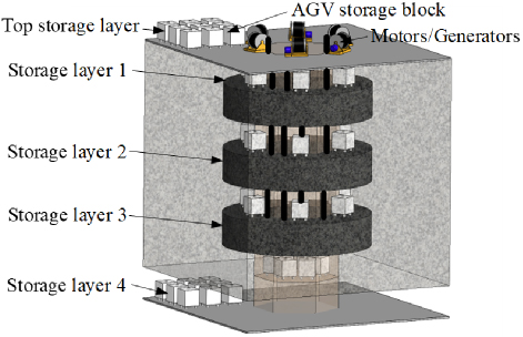
Figure 1: Structure diagram of energy storage system for multi-energy storage motor in single well.
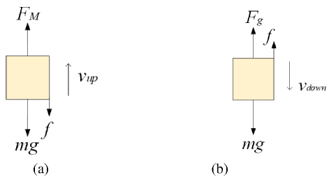
Figure 2: Storage block force analysis diagram under different stages: (a) energy storage stage and (b) power generation stage.
The power of the motor Pup is
| (2) |
where vup is the ascent speed.
In power generation stage, the reverse force Fg is
| (3) |
The power of the generator Pg is
| (4) |
where vdown is the descent speed.
Table 1: Specifications range of SRM
| Parameters | Symbol | Values |
| Stator outer diameter | Dso | 180.0 mm |
| Stator pole length | ps | 20-30 mm |
| Stator yoke length | ys | 9.9-19.9 mm |
| Stator pole angle | Bs | 10.0-18.0∘ |
| Rotor outer diameter | Dro | 99.0 mm |
| Rotor inner diameter | Dri | 30.0-50.0 mm |
| Rotor pole length | pr | 14.0-20.0 mm |
| Rotor yoke length | yr | 9.5-15.5 mm |
| Rotor pole angle | Br | 9.0-17.0∘ |
| Air gap length | g | 0.6 mm |
| Number of turns per slot | N | 12-16 |
| Stack length | L | 150.0 mm |
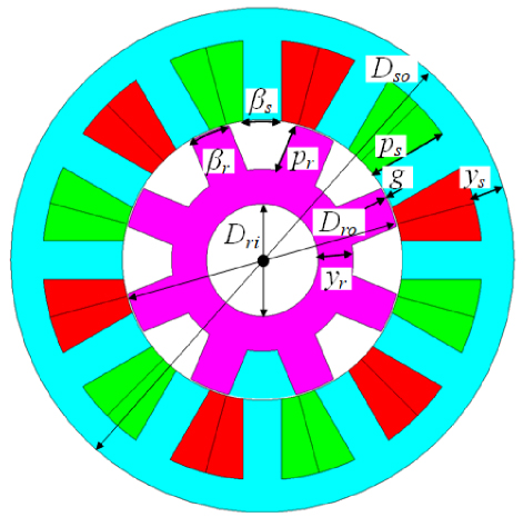
Figure 3: Structure parameter diagram of three-phase 12/8 switched reluctance machine.
Based on the operating speed and power requirements in the motoring stage and the operating speed and power output in the generating stage, the design requirements for the motor can be determined. For this study, considering the large size and power of actual gravity energy storage systems, a prototype motor is designed. The motor has a rated power of 1.8 kW, a rated voltage of 96 V, and a rated speed of 1500 r/min. The initial dimensions of a conventional 12/8 SRM are calculated and summarized in Table 1, and the relevant structural parameters are illustrated in Fig. 3.
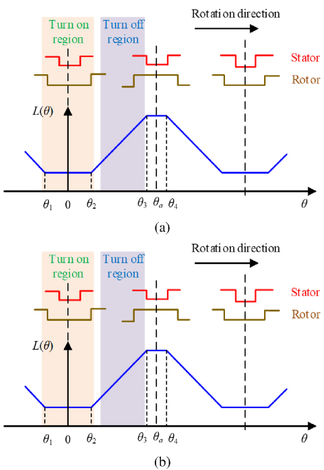
Figure 4: The relationship between the turn-on angle, the turn-off angle and the inductance under different stages: (a) energy storage stage and (b) power generation stage.
III. DESIGN OF NOVEL SWITCHED RELUCTANCE MACHINE SUITABLE FOR GRAVITY ENERGY STORAGE
A. Structure of the salient-pole SRM suitable for gravity energy storage
Assuming that the gravity energy storage SRM operates in energy storage stage during forward rotation, the rising region of the motor’s inductance is utilized, as shown in Fig. 4 (a). Conversely, during reverse rotation, the motor operates in the power generation stage, utilizing the falling region of the inductance, as illustrated in Fig. 4 (b). The inductance L is calculated as
| (5) |
where is the flux linkage and i is the current.
From Fig. 4, it can be observed that in the motoring state, the inductance in the turn-on interval should be minimized, while it should be maximized in the turn-off interval to produce a larger electromagnetic torque. In the generating state, the inductance during the turn-on interval should also be as low as possible to quickly establish the excitation current, while it should be as high as possible during the turn-off interval to slow the current’s decline, thereby generating more power. Based on the above analysis, the stator tooth shape can be optimized to modify the variation characteristics of the inductance with position, meeting the performance requirements of the motor in both motoring and generating states. Therefore, a novel gravity energy storage SRM is proposed in this paper, in which the three-phase 12/8 configuration is shown in Fig. 5 and the stator features a salient-pole design.
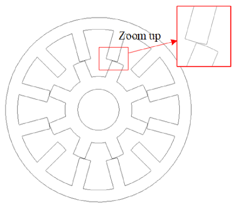
Figure 5: Structure diagram of the new gravity energy storage switched reluctance machine.
B. Multi-objective optimal design suitable for gravity energy storage SRM
In the energy storage stage, the system must provide sufficient torque to lift the weights with minimal torque ripple to reduce mechanical impact and enhance the reliability. In the power generation phase, it must achieve high energy conversion efficiency and sufficient generating power. To meet the requirements of a gravity energy storage system in both motoring and generating stages, the average torque Tavg and torque ripple Tr are selected for the energy storage state, and the power generation Po and power generation efficiency g are selected for the power generation state as the optimization objectives for the design of the gravity energy storage SRM. The torque ripple Tr could be defined as
| (6) |
where T and T are the maximum and minimum torque respectively. The generating efficiency could be obtained as
| (7) |
where P is the input mechanical power in the power generation state.
To meet these dual performance demands, besides fixed values for air gap length g, stator outer diameter Dso, and rotor outer diameter Dro, the design optimizes other parameters including stator pole angle Bs, rotor pole angle Br, stator pole length ps, rotor pole length pr and rotor inner diameter Dri. An optimization process combining sensitivity analysis (SA), response surface (RS) modeling, and a Multi-Objective Grey Wolf Optimization (MOGWO) algorithm is proposed to address the multi-objective optimization problem of the gravity energy storage SRM.
The SA assesses the impact of each optimization parameter on the objective functions, revealing the parameters with the greatest contribution to system performance. A sensitivity index is used to quantify the influence of design variables on optimization objectives, expressed as
| (8) |
where f is the optimization objective function and zi represents the optimization variable.
Weight coefficients are introduced to evaluate four sensitivity indices comprehensively and optimize performance for both motoring and generating states. A comprehensive sensitivity index G(ni) is defined as
| (9) |
where ST, STr, SPo, and Sηg are sensitivity indices for T, Tr, Po, and g, respectively. The weight coefficients 1, 2, 3, and 4 satisfy 1, with all weights set to 0.25 in this paper.
Through single-parameter scanning finite element analysis (FEA) of the optimization parameters, the absolute values of sensitivity indices and the comprehensive sensitivity indices for the four optimization objectives are obtained and shown in Table 2. To visually represent the sensitivity of each variable, the data is displayed in Fig. 6. The greater the absolute value of the sensitivity of a design variable, the more significant its impact on the optimization objectives. From Table 2 and Fig. 6, it can be observed that Bs and Br are the design variables with comprehensive sensitivity indices exceeding 0.25, classified as significant variables since their greatest impact is on the performance of the SRM. The other three parameters, ps, pr, and Dri, have smaller sensitivity indices, classified as insignificant variables. Local SA is limited to the changes of local variables and does not apply to the global range. Significant variables require further optimization, while insignificant variables can be fixed at their optimal values by a single-parameter scanning method. Consequently, the insignificant variables are set as constants: ps is 24.6 mm, pr is 19 mm,and Dri is 35 mm, which will not be treated as design variables in the subsequent optimization process.
Table 2: Sensitivity indices of design parameters
| Variables | |STavg| | |STr| | |SPo| | |Sηg| | G(ni) |
| Br | 0.1894 | 0.4950 | 0.2554 | 0.1834 | 0.2808 |
| Bs | 0.2108 | 0.8580 | 0.2722 | 0.0756 | 0.3541 |
| pr | 0.0103 | 0.0171 | 0.0207 | 0.0014 | 0.0124 |
| ps | 0.0874 | 0.0385 | 0.0958 | 0.0476 | 0.0673 |
| Dri | 0.0002 | 0.0001 | 0.0010 | 0.0008 | 0.0005 |
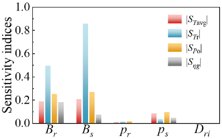
Figure 6: Sensitivity indices of variables to the optimization objective.
RS analysis, by constructing mathematical models, effectively reduces the number of experiments, quantitatively evaluates the interactions between design variables and reveals nonlinear relationships, which can be used in motor parameter optimization to predict objective function values, optimize parameter combinations, and significantly improve optimization efficiency and accuracy. For the two significant variables of the SRM, the Central Composite Design (CCD) experimental method is employed. CCD enhances the ability to capture interaction effects between parameters within the design space by adding center points and axial points, providing more precise model predictions and efficiently fits the RS model with fewer experimental runs. To obtain the optimal values of the two significant variables Bs and Br, a CCD RS analysis is applied and its variable levels are shown in Table 3.
Table 3: CCD response surface analysis variable levels
| Variables | Levels | ||||
| -1.414 | -1 | 0 | 1 | 1.414 | |
| Br (deg) | 13.586 | 14.0 | 15.0 | 16.0 | 16.414 |
| Bs (deg) | 12.586 | 13.0 | 14.0 | 15.0 | 15.414 |
The CCD experimental scheme included 13 different combinations. The motor output performance conducted by FEA corresponding to each experimental point is recorded. Using Design-Expert, the simulation results of the sampled points are analyzed and a quadratic regression function is fitted for the design variables and the four optimization objectives, resulting in the RS models shown in Fig. 7. The P-values of all four CCD RS experiments are less than 0.05, indicating that the two variables have a notable impact on the optimization objectives. Furthermore, the multiple correlation coefficients R2 are all greater than 0.98. The closer the R2 value is to 1, the better the model fits the motor performance. These results demonstrate that the RS is well fitted and the experiments are reasonable.
The MOGWO algorithm is an evolutionary algorithm inspired by the hunting behavior of grey wolf packs. It simultaneously considers multiple objective functions and introduces an external population, known as the Archive, to store non-dominated optimal solutions while eliminating numerous similar solutions. A leader selection strategy is used in MOGWO, where leaders are chosen from the Archive for guiding the hunting process, ultimately converging to a set of optimal Pareto front solutions. In this paper, MOGWO is used to further optimize significant variables to achieve optimal SRM performance, with the initial population and Archive population sizes set to 100 and iterations set to 50.
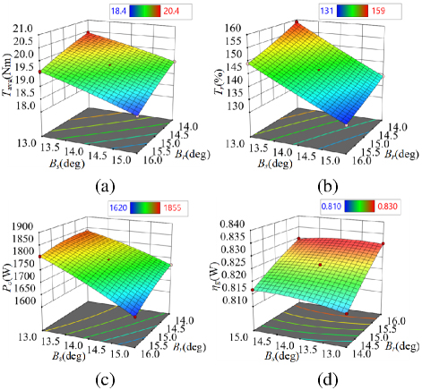
Figure 7: Response surface of (a) Tavg, (b) Tr, (c) Po, and (d) g.
The Pareto solution set obtained is shown in Fig. 8, where Fig. 8 (a) illustrates the optimal solution space distribution based on Tavg, Po, and g, and Fig. 8 (b) shows the distribution based on Tavg ,Tr, and g. After filtering out some unreasonable points, three superior solutions are selected from the set based on the performance requirements of the gravity energy storage system, and the performance of three optimized points is listed in Table 4. A comparison reveals that although Design 1 has the lowest torque ripple, its power output and efficiency in the generating mode are relatively low. Designs 2 and 3 exhibit better overall motor performance. Ultimately, Design 2 with superior performance is chosen as the optimal size design. The values of the two significant variables in the optimal design are Br as 15.27∘ and Bs as 12.84∘.
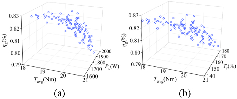
Figure 8: The Pareto fronts obtained by MOGWO of optimization objectives: (a) Tavg, Po, and g and (b) Tavg, Tr, and g.
Table 4: SRM performance of selected optimal designs
| Variables | Initial Design | Design 1 | Design 2 | Design 3 |
| Br (deg) | 14.0 | 13.52 | 15.27 | 14.79 |
| Bs (deg) | 13.0 | 14.11 | 12.84 | 13.04 |
| Tavg (Nm) | 20.247 | 20.431 | 20.419 | 20.416 |
| Tr (%) | 165.09 | 149.48 | 153.07 | 153.56 |
| Po (W) | 1835.55 | 1853.96 | 1904.44 | 1900.04 |
| g (%) | 81.290 | 81.710 | 82.996 | 82.595 |
IV. SIMULATION RESULT
A. Static characteristic analysis
Based on the optimized dimensions obtained through multi-objective optimization, a finite element model of the SRM is constructed and its electromagnetic performance is analyzed. Figure 9 illustrates the magnetic density distribution at the unaligned and aligned positions when a 30 A current is applied to the A-phase winding. At the unaligned position, the magnetic density of the stator and rotor poles is approximately 0.15 T, and at the minimum air gap of the stator salient teeth the flux value decreases to 0.05 T, confirming the flux cancellation effect at the unaligned position. At the aligned position, the stator and rotor poles are aligned, with a flux density of about 1.2 T. At the stator’s minimum air gap, the flux value slightly increases to around 1.4 T.
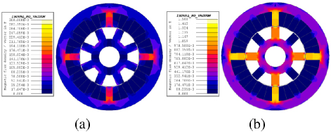
Figure 9: Magnetic density distribution diagram of the SRM: (a) unaligned position and (b) aligned position.
The static electromagnetic force curves for the A-phase as the current increases from 10 A to 100 A are presented in Fig. 10 (a). Across different current levels, the trend of static electromagnetic force varying with the rotor position remains consistent, and the force increases with higher current. Figure 10 (b) depicts the self-inductance curves of the A-phase winding as the current rises from 10 A to 100 A. Due to magnetic saturation, the inductance decreases with increasing current at aligned positions, and the minimum inductance is almost equal at the unaligned position. At 100 A, the maximum inductance is 1.25 mH and the minimum inductance is 0.38 mH. At 10 A, the maximum inductance is 3.08 mH, while the minimum inductance is 0.38 mH, resulting in a non-saturation maximum-to-minimum inductance ratio of 8.11.
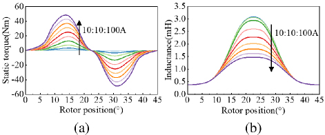
Figure 10: Static characteristic of SRM: (a) torque characteristic and (b) inductance characteristic.
B. Dynamic characteristic analysis
1. In the energy storage stage
To verify the dynamic performance of the SRM, simulations are conducted by MATLAB/Simulink. In the energy storage stage, the motor speed is set to 1500 r/min and the conduction angle is set to 0-15∘. The motoring current and torque waveforms of angle position control are given in Fig. 11. The maximum torque is 31.09 Nm, the minimum torque is 5.58 Nm, the average torque is 19.41 Nm and torque ripple is 131.43%.
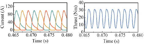
Figure 11: Current and torque waveforms of the motor in electric state.
2. In the power generation stage
The generating current and torque waveforms of angle position control are given in Fig. 12. The speed is set to 1500 r/min, and the generator is controlled to turn-on at 25∘ and turn-off at 35∘. From Fig. 12, the average torque of the generator is 15.15 Nm. The generating power is the difference between the power of the power generation phase and the power of the excitation phase, which yields a generating power of 2075 W and a power generation efficiency of 87.2%.
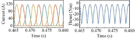
Figure 12: Current and torque waveforms of the motor in generate state.
Table 5: Performance comparison of two SRMs
| Performance | Traditional SRM | Proposed SRM |
| Tavg (Nm) | 18.339 | 20.419 |
| Tr (%) | 154.186 | 153.07 |
| Po (W) | 1641.927 | 1904.440 |
| g (%) | 81.711 | 82.996 |
C. Comparison with traditional SRM
To verify the superiority of the proposed salient stator tooth 12/8 structure SRM, a comparison is made with the traditional structure SRM. Except for the different tooth shape of the stator, the remaining dimensions of the traditional SRM are identical to those of the proposed SRM with the optimal structure.
The inductance characteristics of the traditional SRM are tested. When the phase A current is 10 A, the maximum inductance is 2.42 mH, the minimum inductance is 0.38 mH, and the maximum-minimum inductance ratio is 6.37, while the maximum-minimum inductance ratio of the proposed SRM under the same conditions is 8.11. Thus, the proposed SRM has a larger maximum to minimum inductance ratio under unsaturated currents.
Comparison of the performance of the two motors is given in Table 5. It can be seen that the average torque and power generation of the salient stator tooth structure SRM are significantly improved compared to the traditional SRM, which confirms the superiority of employing the proposed novel structure SRM as an energy storage machine.
V. CONCLUSION
In this paper, a salient stator tooth 12/8 structure SRM that can realize high performance is designed for gravity energy storage. Four design evaluation indicators are proposed, which include average torque and torque ripple under energy storage conditions, as well as power generation efficiency and power generation capacity under power generation conditions. A multi-objective optimization design is then conducted, improving the performance compared to the initial design. The static electromagnetic and dynamic characteristics under energy storage stage and power generation stage are carried out. The simulation results show that the novel machine structure and optimization design method proposed in this paper are effective, which has certain reference significance for the design of energy storage machine.
ACKNOWLEDGMENT
This work was supported in part by the Guangdong Basic and Applied Basic Research Foundation under Grant 2025A1515011254, the Xuzhou Science and Technology Innovation Basic Research Project under Grant KC23021, China Postdoctoral Foundation Project under Grant 2023M733749, 2022 China-CEEC University Joint Education Program (2022200), 2023 China-CEEC University Joint Education Program (2023304).
REFERENCES
[1] F. Li, J. Xie, Y. Fan, and J. Qiu, “Potential of different forms of gravity energy storage,” Sustainable Energy Technol. Assess., vol. 64, pp. 1-11, Mar. 2024.
[2] W. Tong, Z. Lu, J. D. Hunt, H. Zhao, M. Han, and G. Zhao, “Energy management system for modular-gravity energy storage plant,” J. Energy Storage, vol. 74, pp. 1-14, Oct. 2023.
[3] P. Kropotin, O. Penkov, and I. Marchuk, “On using unstabilized compressed earth blocks as suspended weights in gravity energy storages,” J. Energy Storage, vol. 72, pp. 1-10, Aug. 2023.
[4] L. Ge, N. Du, J. Song, J. Zhang, Z. Fan, D. Zhang, and S. Song, “Advanced technology of switched reluctance machines in more electric aircraft: A review,” IEEE Trans. Power Electron., vol. 40, no. 1, pp. 195-216, Jan. 2025.
[5] X. Guo, S. Zeng, R. Zhong, and W. Hua, “High-precision injection current sampling scheme for direct drive low-speed position sensorless control of switched reluctance machine,” IEEE Trans. Ind. Electron., vol. 71, no. 11, pp. 13754-13765, Nov. 2024.
[6] H. Wang, Y. Xue, J. Du, and H. Li, “Design and evaluation of modular stator hybrid-excitation switched reluctance motor for torque performance improvement,” IEEE Trans. Ind. Electron., vol. 71, no. 10, pp. 12814-12823, Oct. 2024.
[7] A. Madanimohammadi, M. Abbasian, M. Delshad, and H. Saghafi, “Electromagnetic and thermal analysis of a 6/4 induction switched reluctance machine for electric vehicle application,” Applied Computational Electromagnetics Society (ACES) Journal, vol. 38, no. 05, pp. 361-370, May 2023.
[8] X. Sun, K. Diao, G. Lei, Y. Guo, and J. Zhu, “Study on segmented-rotor switched reluctance motors with different rotor pole numbers for BSG system of hybrid electric vehicles,” IEEE Trans. Veh. Technol., vol. 68, no. 6, pp. 5537-5547, June 2019.
[9] W. Ding, H. Bian, K. Song, Y. Li, and K. Li, “Enhancement of a 12/4 hybrid-excitation switched reluctance machine with both segmented-stator and -rotor,” IEEE Trans. Ind. Electron., vol. 68, no. 10, pp. 9229-9241, Oct. 2021.
[10] F. Yu, H. Chen, W. Yan, V. F. Pires, J. F. Martins, P. Rafajdus, A. Musolino, L. Sani, M. P. Aguirre, M. A. Saqib, M. Orabi, and X. Li, “Design and multiobjective optimization of a double-stator axial flux SRM with full-pitch winding configuration,” IEEE Trans. Transp. Electrif., vol. 8, no. 4, pp. 4348-4364, Dec. 2022.
[11] L. Liu, Y. Huang, M. Zhao, and Y. Ruan, “Parametric modeling and optimization of switched reluctance motor for EV,” Applied Computational Electromagnetics Society (ACES) Journal, vol. 37, no. 09, pp. 948-958, Sep. 2022.
[12] D. Marcsa and M. Kuczmann, “Design and control for torque ripple reduction of a 3-phase switched reluctance motor,” Comput. Math. Appl., vol. 74, no. 1, pp. 89-95, July 2017.
[13] N. Prasad, S. Jain, and S. Gupta, “Comparative analysis of new improved force split-teeth linear switched reluctance motor for high-speed transit systems,” Sadhana-Academy Proc. Eng. Sci., vol. 45, no. 1, pp. 1-13, June 2020.
[14] Q. Li, W. Sun, L. Sun, and L. Li, “Rotor segment split and its optimization of axial-field dual-rotor segmented switched reluctance machine,” Energy Rep., vol. 6, no. S9, pp. 1144-1150, Dec. 2020.
[15] G. Guidkaya, E. D. K. Fankem, and J. Y. Effa, “A new rotor shape design of 6/2 switched reluctance motor: Comparative analysis of its chaotic behavior with other structures,” J. Electr. Eng. Technol., vol. 16, no. 1, pp. 309-320, Oct. 2020.
[16] H. Ma, C. Huang, X. Liu, W. Shi, and W. Liu, “The effect of a single-sided pole shoe and slot on reducing torque ripple in a switched reluctance motor,” Concurrency Comput. Pract. Exper., vol. 32, no. 19, p. e5810, May 2020.
[17] W. Yan, H. Chen, S. Liao, Y. Liu, and H. Cheng, “Design of a low-ripple double-modular-stator switched reluctance machine for electric vehicle applications,” IEEE Trans. Transp. Electrif., vol. 7, no. 3, pp. 1349-1358, Sep. 2021.
[18] P. Upadhyay and Ragavan K., “Design of two-phase 4/6 switched reluctance motor for bidirectional starting in washing machine application,” IEEE Trans. Ind. Appl., vol. 59, no. 2, pp. 1519-1529, Mar. 2023.
[19] K. Diao, G. Bramerdorfer, X. Sun, Z. Yang, and S. Han, “Multiobjective design optimization of a novel switched reluctance motor with unequal alternating stator yoke segments,” IEEE Trans. Transp. Electrif., vol. 9, no. 1, pp. 512-521, Mar. 2023.
BIOGRAPHIES
Wenju Yan (M’19) received the B.S. degree in Electrical Engineering and Automation from the China University of Mining and Technology, Xuzhou, China, in 2013. He received the Ph.D. degree in electrical engineering from the China University of Mining and Technology, Xuzhou, China, in 2018. Since 2018, he has been with China University of Mining and Technology, where he is currently an associate professor in the School of Electrical Engineering. His current research interests include electric vehicles, electric traction, iron loss analysis, and motor design.

Xinzhu Sun received the B.S degree from of Electrical Engineering, Sichuan University, Chengdu, China, in 2023, She is currently working towards the M.S. degree in electrical engineering from the China University of Mining and Technology, Xuzhou, China. Her research interests include integrated drive systems for electric vehicles and energy storage.
Jun Xin received the B.S. degree in Electrical Engineering and Automation from the China University of Mining and Technology, Xuzhou, China, in 2023. He is currently working toward the M.S. degree in electrical engineering from the China University of Mining and Technology, Xuzhou, China. His research interests include integrated drive systems for electric vehicles and double-stator switched reluctance motors.

Hao Chen received the B.S. and Ph.D. degrees in Electrical Engineering from the Department of Automatic Control, Nanjing University of Aeronautics and Astronautics, Nanjing, China, in 1991 and 1996, respectively. In 1998, he became an Associate Professor with the School of Information and Electrical Engineering, China University of Mining and Technology, Xuzhou, China, where he has been a professor since 2001. From 2002 to 2003, he was a Visiting Professor at Kyungsung University, Busan, Korea. Since 2008, he is Adjunct Professor at the University of Western Australia, Perth, Australia. He is the author of one book and has authored more than 200 papers. His current research interests include motor control, linear launcher, electric vehicles, electric traction, servo drives, and wind power generator control. Chen was the recipient of both the Prize of Science and Technology of Chinese Youth and the Prize of the Fok Ying Tong Education Foundation for Youth Teachers in both 2004. He became the Chinese New Century National Hundred-Thousand Ten-Thousand Talents Engineering National Talent in 2007 and won the Government Especial Allowance of People’s Republic of China State Department in 2006.

Yang Wang received the B.S. degree in Electrical Engineering and Automation from the Hefei University of Technology, Hefei, China, in 2023. He is currently working toward the M.S. degree in electrical engineering from the China University of Mining and Technology, Xuzhou, China. His research interests include electric machine control.

Vuong Dang Quoc received the Ph.D. degree in electrical engineering in July 2013 at the Faculty of Applied Sciences at the University of Liège in Belgium. He moved to Hanoi University of Science and Technology in September 2013, where he is currently working as a deputy director of Training Center of Electrical and Electrical Engineering, School of Electrical Engineering (SEEE), Hanoi University of Science and Technology (HUST). He became an associate professor in 2020. Vuong’s research domain encompasses modeling of electromagnetic systems, electrical machines, optimization method, numerical methods and subproblem methods.
Thanh Nguyen Vureceived the Ph.D. degree in 2015 from the Department of Electrical Engineering, School of Electrical Engineering, Hanoi University of Science and Technology (HUST). He is currently working as a Head of Department of Electrical Engineering, School of Electrical and Electronic Engineering, HUST. His research domain encompasses modeling of electrical machines, optimization and numerical methods.
ACES JOURNAL, Vol. 40, No. 9, 831–839
doi: 10.13052/2024.ACES.J.400904
© 2025 River Publishers