Research on Switched Reluctance Motor Power Converters in Multi-port Low-carbon Building Microgrid System
Cheng Liu, Yu Zhao, Qing Wang, Xiaofeng Wan, and Lei Cao
1School of Information Engineering
Nanchang University, Nanchang 330031, China
liucheng08@ncu.edu.cn, wangq@ncu.edu.cn, xfwan@ncu.edu.cn
2School of Advanced Manufacturing
Nanchang University, Nanchang 330031, China
3Architecture and Design College
Nanchang University, Nanchang 330031, China
caolei@ncu.edu.cn
4State Grid Zhejiang Electric Power Co. Ltd.
Daishan County Power Supply Company, Daishan 316229, China
2235272392@qq.com4
Submitted On: June 13, 2024; Accepted On: July 25, 2025
ABSTRACT
This paper presents research on a dual-source three-level power converter for a switched reluctance motor (SRM) in a multi-port low-carbon building microgrid system. A front-end circuit is added to the proposed power converter based on the conventional asymmetric half-bridge power converter (AHBPC) for power flow control. It can achieve a three-level power supply by using solar photovoltaic (PV) cells and lead-acid batteries which can be replaced with other power supply modules as needed without affecting system functionality. Three working modes can be achieved according to actual applications by a simple strategy. With the proposed converter, system efficiency and dynamic response can be improved. Working modes of the proposed solution are explained and current paths in the proposed converter are analyzed in detail. Finally, experimental results on a four-phase 8/6 SRM platform are given to confirm the effectiveness of the proposed solution.
Index Terms: Asymmetric half-bridge power converter, dual-source three-level power converter, power flow control, switched reluctance motor.
I. INTRODUCTION
In recent years, the global climate change problem has become increasingly serious, and low-carbon environmental protection has become a global consensus. In this context, the low-carbon transformation of building construction becomes particularly important. Figure 1 shows a multi-port microgrid system of a low-carbon building. In this model, a switched reluctance motor (SRM) can drive the loads through photovoltaic (PV) and battery hybrid or separate power supply, such as elevator lifting and water pumping. Furthermore, the power supply modes can be applied to various electrical appliances and charging electric vehicles. The excess electric energy generated by PV power generation and gravity potential energy generated by elevator lifting can be recovered through an energy storage system. In [1], a general power distribution system of buildings, namely, PVs, energy storage, direct current, and flexibility (PEDF) is proposed to provide an effective solution from the demand side. As the core component of the low-carbon building microgrid drive system, drive motor performance can affect operation of the microgrid system directly. Switched reluctance machines have been studied for many years and have become one of the most promising candidates in renewable-energy-related industries such as wind power systems, gas energy recovery systems, electric vehicles and wave energysystems [2–5].
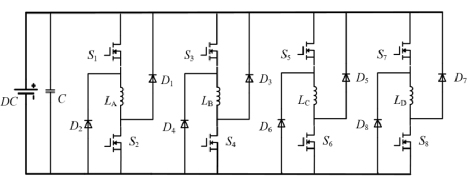
Figure 1: A multi-port microgrid system of a low-carbon building.
The power converter, as the core part of the SRM drive system, plays a decisive role in the performance of the entire motor system. The conventional power converter is mainly based on an asymmetric half-bridge (AHB) structure, with the most significant advantages of simple structure, flexible control strategy, independent phase to phase, and good fault tolerance performance. However, there are also some drawbacks, such as the impact of a single power supply on the safety of SRM systems; the excitation speed and demagnetization speed are relatively slow, which affects system efficiency; and the lack of energy feedback methods will limit the utilization rate of energy. In order to solve the above problems, new power converter topology is a hot topic in the field of SRM. In [6], a power converter is proposed for excitation and freewheeling functions by means of auxiliary windings and capacitors, which can control one phase through a MOSFET. In [7], a power converter topology is given for achieving structure simplification through reusing the MOSFETs on each phase winding. It can achieve a reduction of the number of power MOSFETs, reducing component losses and improving the performance of the SRM system. However, this kind of power converter will make the phase windings no longer independent of each other, and the reused power MOSFETs will take on the function of controlling the commutation of polyphase windings. If the reused power MOSFETs fail to control, it will seriously affect the normal operation of SRM and reduce the fault tolerance performance of the motorsystem.
To achieve high-speed excitation, a method of increasing the excitation voltage of SRM by adding a boost-type DC-DC converter is studied in [8]. To achieve high voltage excitation and demagnetization, a power converter topology is presented in [9]. Although the two different power converters proposed in [8] and [9] can both improve the system operating voltage, their power supply level cannot be changed flexibly according to actual operating requirements, which still has certain limitations.
As recognized, system efficiency and dynamic performance are two hot topics for SRM. For instance, some multilevel converter topologies are presented in [10–15]. In [10], a method of hybrid operation of two asymmetric half-bridge power converters (AHBPCs) is employed to achieve multilevel power supply; in [11–13], the modular designs for batteries are studied; in [14], a topology for power converter is presented by adding diode and power MOSFET to each phase; and in [15], a method of designing three excitation and freewheeling circuits for three power sources is presented. However, with the increasing complexity or cost of the system, the practicality of the system will decrease. Additionally, some fault tolerant control strategies are studied in [16–18].
In this paper, a dual-source three-level power converter topology for SRM is studied. According to the proposed topology, the operating principle, control method, and implementation of fast excitation and demagnetization functions during the operation are introduced. Then, a comparison of system efficiency and torque ripple of the proposed power converter and the conventional AHBPC is given. To validate the performance of the proposed power converter, simulation results and experimental results are given in sections III and IV, respectively. The paper is concluded in section V.
II. Topology and operational modes
A. Proposed topology
Figure 2 shows conventional AHBPC topology. Whether in excitation or demagnetization state, the voltage on the winding is the power supply voltage. This will result in a relatively slow excitation and demagnetization process during high-speed motor operation, affecting the performance of the SRM system and reducing system efficiency.
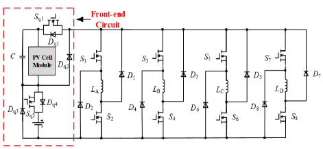
Figure 2: Topology of conventional asymmetric half-bridge power converter.
In the proposed topology of AHBPC, which is shown in Fig. 3, a front-end circuit is added to the conventional AHBPC. The front-end circuit consists of a PV cell (UP12 V) and a battery (UE12 V), a capacitor, two diodes (Dq2 and Dq3) and two MOSFETs. Diodes Dq1 and Dq4 are internal diodes in Sq1 and Sq2, respectively. There are three operation modes in the system according to the proposed converter: PV cell independent power supply, battery independent power supply and dual-source hybrid power supply. To achieve switching between the three power supply modes, the choice of system voltage will be controlled by the two MOSFETs (Sq1 and Sq2) in the front-end circuit. Three levels of output based on the two power supplies can be achieved. To improve the stability of the power supply, a capacitor is added to the front-end circuit. It can also serve as a connecting element of the energy feedback path for the freewheeling current simultaneously.
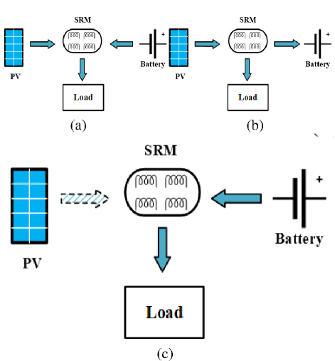
Figure 3: Topology of proposed power converter.
B. Analysis of working modes
During each operation cycle of the motor, each phase winding undergoes three working states: excitation state, freewheeling (demagnetization) state, and zero-voltage freewheeling state. As mentioned, the three power supply modes for the proposed power converter can be switched by controlling Sq1 and Sq2 of the front-end circuit. Then, the level conversion will be achieved and the excitation and demagnetization process can be optimized.
As can be seen in Fig. 3, the topology of the proposed power converter is composed of three energy terminals: PV cell, battery, and SRM. The power converter is the bridge that connects the three terminals to each other. Figure 4 shows the three operation modes of the proposed power converter.
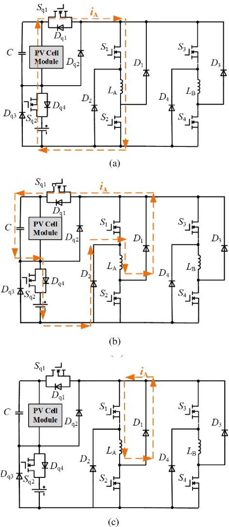
Figure 4: Three operation modes of the proposed power converter: (a) mode 1, (b) mode 2, and (c) mode 3.
To switch between the operation modes, the corresponding MOSTETs (Sq1 and Sq2) actions are shown in Table 1. In mode 1, the PV cell and battery are both power sources for the SRM system. In mode 2, the PV cell is the power source and the battery is idle. In mode 3, the battery is the power source and the PV cell is idle.
Table 1: Sq1 and Sq2 actions under different modes
| Mode | Sq1 and Sq2 |
| 1. Dual-source hybrid power supply | Sq1 and Sq2 turn-on |
| 2. Photovoltaic cell power supply | Sq1 turn-on; Sq2 turn-off |
| 3. Battery power supply | Sq1 turn-off; Sq2 turn-on |
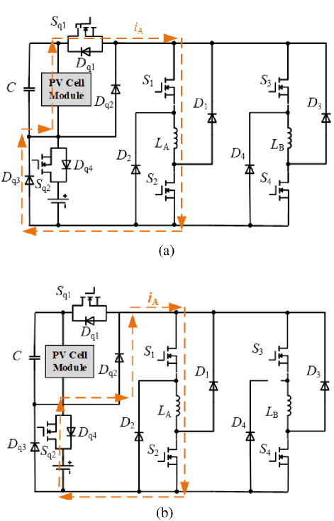
Figure 5: Working states at mode 1: (a) winding excitation state, (b) freewheeling state, and (c) zero-voltage freewheeling state.
Taking phase A as an example, Fig. 5 shows the three working states in mode 1. The current paths are shown as the dashed line in Fig. 5. As shown in Fig. 5 (a), the voltage drops of phase A can be expressed as:
| (1) |
where UA, UP, UE, US, Is, iand Ron stand for voltage of phase A, voltage of PV cell, voltage of battery, voltage drop of each MOSFET, the transient current flowing through each MOSFET, the current of phase A and on-state resistance of each MOSFET, respectively. In this case, since LA is the only load in the loop, the current Is is equal to iA,i.e. IsiA.
As can be seen in Fig. 5 (b), when the excitation process ends, S1 and S2 will be turned off. Phase A enters the demagnetization mode, and the power converter starts working in a freewheeling state. The voltage drops of phase A can be expressed as:
| (2) |
where UDC and UC stand for bus voltage and capacitor voltage drop; UD stands for the voltage drop of each diode on the current flow path; UO, ID and RZ stand for the turn-on voltage of each diode, the transient current flowing through each diode and dynamic resistance of each diode, respectively.
As shown in Fig. 5 (c), when A-phase winding enters zero-voltage freewheeling state, the freewheeling voltage of phase A is 0 V, i.e. UA=0.
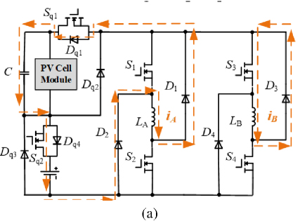
Figure 6: Excitation state in modes 2 and 3: (a) under photovoltaic cell power supply and (b) under battery power supply.
In mode 1, the excitation voltage and demagnetization voltage of the SRM are maintained at a constant power supply voltage. Therefore, the motor cannot perform high-level excitation and high-level demagnetization.
Figure 6 shows the excitation state of mode 2 and mode 3. The A-phase winding is energized by PV cell and battery through different diodes.
According to the proposed power converter, the freewheeling current flow path is the same in mode 2 and mode 3. Therefore, the following analysis of the freewheeling current is carried out in the mode of battery independent power supply (mode 3). In actual operation, the freewheeling current of each phase winding may overlap with other phases. Thus, it is not possible to simply discuss the freewheeling current or excitation situation of a single phase. Taking phase A and phase B as examples, the following five cases areanalyzed.
Figure 7 (a) shows the current flow path in case 1. In the first case, phase A enters freewheeling state while phase B is in zero-voltage freewheeling state. Capacitor C and battery will be charged by phase A. The phase A voltage drop and phase B voltage drop can be expressed as:
| (3) |
where UB stands for the voltage drop of phase B.
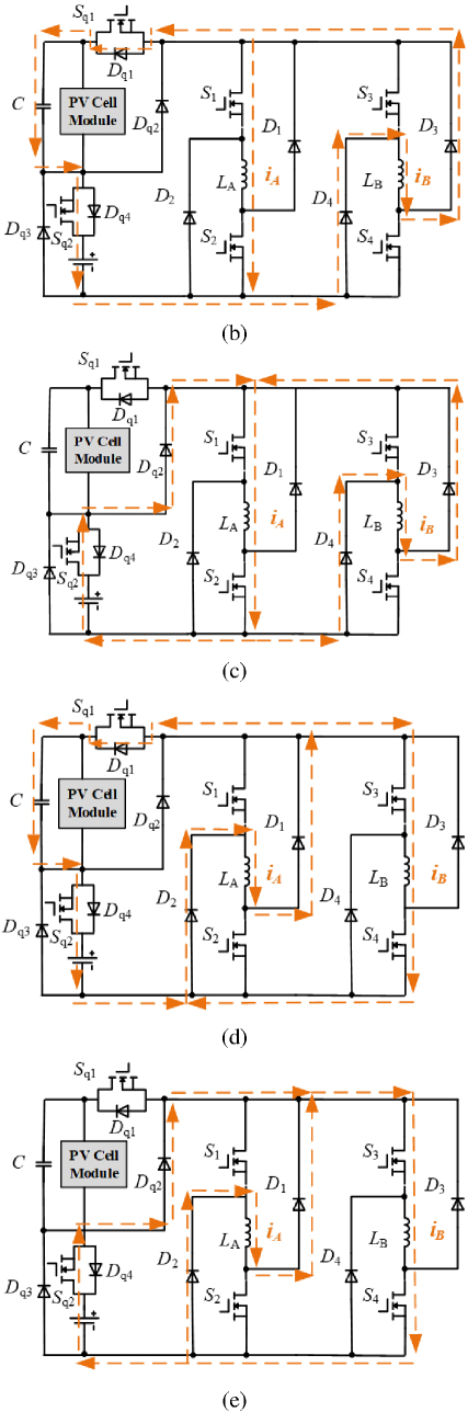
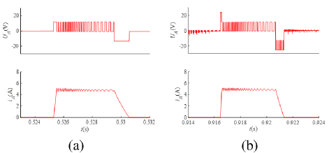
Figure 7: Five cases in freewheeling state in mode 3: (a) case 1, (b) case 2, (c) case 3, (d) case 4, and (e) case 5.
In case 2, phase A enters excitation state, while phase B is in the freewheeling state. If iBiA, where iBstands for the current of phase B, the energy onB-phase winding is not only for charging the capacitor C and battery, but also providing energy for phase A. The current flow path can be seen in Fig. 7 (b). The voltage drop of phases A and B can be expressed as:
| (4) |
In case 3, phases A and B are in the same state as in case 2, but iB is less than iA (iBiA). At this time, the voltage drops of phase A and phase B can be expressed as:
| (5) |
The current flow path is shown in Fig. 7 (c), and the excitation voltage of phase A is no longer determined by phase B.
In case 4, phase A enters freewheeling state, while phase B is in the excitation state. If iAiB, the A-phase winding feeds back electrical energy to the capacitor C and the battery, while providing excitation current to the B-phase winding. The current flow path is shown in Fig. 7 (d). The voltage drop of phase A and B can be expressed as:
| (6) |
In case 5, phase A and phase B are in the same state as in case 4. However, contrary to case 4, if iAiB, A-phase winding no longer provides excitation current to B-phase winding. The current flow path can be seen in Fig. 7 (e). At this time, the voltage drop of phase A and B can be expressed as:
| (7) |
Through the analysis of mode 3, it is clear that both the voltage of the A-phase and B-phase winding in case 1, case 2 and case 4 can meet the requirements of high-level demagnetization and high-level excitation.
III. SIMULATION ANALYSIS
A. Phase voltage and current analysis
In order to verify the feasibility of the proposed power converter, the performance comparison is studied in MATLAB/Simulink between conventional AHBPC and proposed power converter for proof-of-concept.
In simulation, the rotor speed is set as 600 r/min, the turn-on angle is set as 5∘, the turn-off angle is set as 20∘, and the output voltage of both the battery and PV cell is 12 V. Taking phase A as an example, Fig. 8 shows the voltage and current waveform of conventional AHBPC and proposed power converter in excitation state and demagnetization state. At this time, the conventional AHBPC is powered by battery, while the proposed power converter is powered by PV cell.
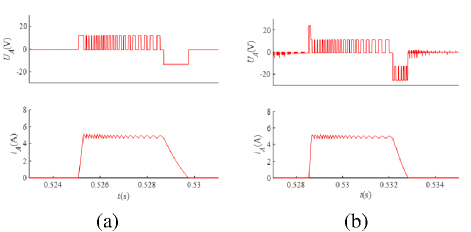
Figure 8: Comparison of voltage and current waveform between conventional AHBPC and proposed power converter in excitation state and demagnetization state when rotor speed is 600 r/min in mode 2: (a) with conventional AHBPC and (b) with proposed power converter.
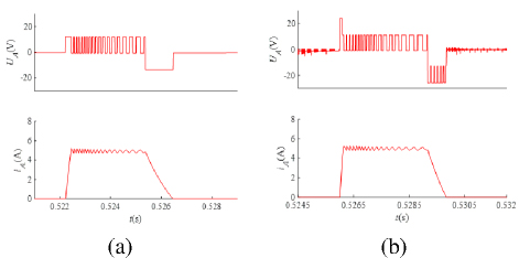
Figure 9: Comparison of voltage and current waveform between conventional AHBPC and the proposed power converter in excitation state and demagnetization state when rotor speed is 700 r/min in mode 3: (a) with conventional AHBPC and (b) with proposed power converter.
As shown in Fig. 8 (a), in the excitation state, the excitation voltage of the A-phase winding is stable at 12 V. In the demagnetization state, the demagnetization voltage of the A-phase winding is stable at -12 V. The constant excitation voltage and demagnetization voltage result in a longer excitation and demagnetization process of the winding, and this will slow the increase and decrease of current, which limits the performance of the SRM system. In Fig. 8 (b), when Sq1 and Sq2 are switched on, the excitation voltage of the phase-A winding is the sum of the voltages of the PV cell and the battery, which is 24 V, enabling fast excitation of the SRM system. After the high-level excitation is over, the excitation voltage of proposed power converter drops to 12 V until the end of the excitation process. There are two demagnetization voltages in demagnetization state, which are -12 V and -24 V. Under the -24 V demagnetization voltage, fast demagnetization can be achieved. In the fast excitation and demagnetization states, the possibility of negative torque generation can be reduced and the performance of the SRM system can be improved.
Taking phase A as an example, Figs. 9–12 show the comparison of voltage and current waveform between conventional AHBPC and the proposed power converter in battery-independent power supply mode under different rotor speed where the turn-on angle and the turn-off angle are set as 5∘ and 20∘, respectively.
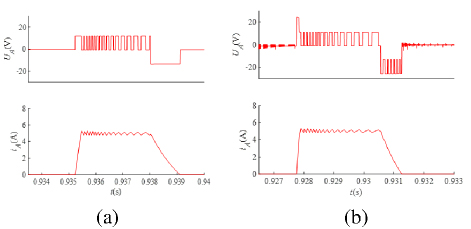
Figure 10: Comparison of voltage and current waveform between conventional AHBPC and proposed power converter in excitation state and demagnetization state when rotor speed is 800 r/min in mode 3: (a) with conventional AHBPC and (b) with proposed power converter.
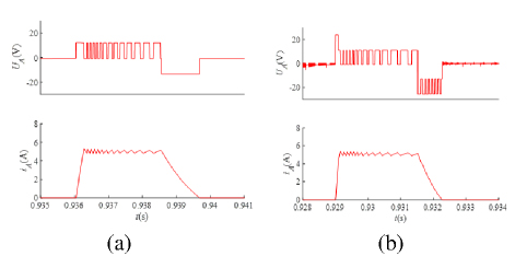
Figure 11: Comparison of voltage and current waveform between conventional AHBPC and proposed power converter in excitation state and demagnetization state when rotor speed is 900 r/min in mode 3: (a) with AHBPC and (b) with proposed power converter.
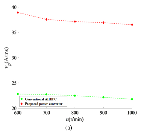
Figure 12: Comparison of voltage and current waveform between conventional AHBPC and proposed power converter in excitation state and demagnetization state when rotor speed is 1000 r/min in mode 3: (a) with conventional AHBPC and (b) with proposed power converter.
As shown in Figs. 9–12, when the motor operates at higher speeds, conventional AHBPCs are limited by constant excitation voltage and demagnetization voltage, and SRMs are increasingly affected by the speed of phase current rise and fall, making it difficult to further improve the system performance under high rotor speed conditions. During the process of continuously increasing the rotor speed from 700 r/min to 1000 r/min, the SRMs system with proposed power converter powered by a 12 V battery can still achieve high-level excitation and demagnetization. Compared with conventional AHBPC, the performance of the SRM system can be improved more effectively with the proposed power converter at high rotor speeds.
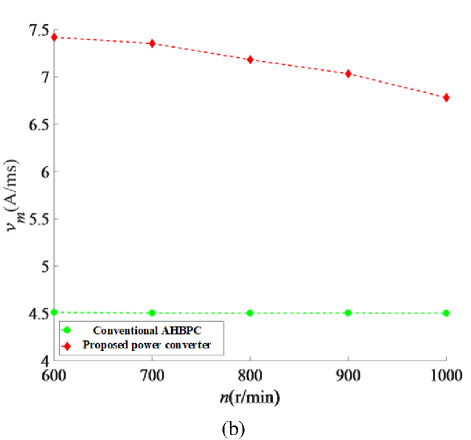
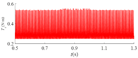
Figure 13: Comparison of the phase current rise and fall velocity in the SRM system when using conventional AHBPC (green dash line) and proposed power converter (red dash line): (a) comparison of vp with two different power converters and (b) comparison of vm with two different power converters.
Figure 13 shows a comparison of the phase current rise and fall velocity in the SRM system in the case of using conventional AHBPC and proposed power converter at different rotor speeds. In Fig. 13, vp and vm stand for the phase current rise velocity when the phase-A excitation current reaches the upper limit of the chopping current for the first time and the phase demagnetization current fall velocity after chopping, respectively. As can be seen from Figs. 13 (a) and (b), when using the proposed power converter, vp and vm are both greater at different motor speeds than when using conventional AHBPC. In other words, the system performance can be improved because the excitation and demagnetization processes can be completed in a shorter time with proposed power converter.
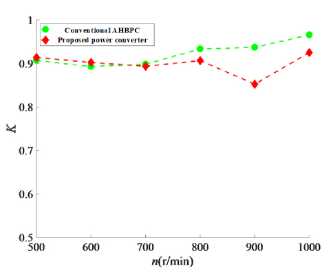
Figure 14: Torque waveform with proposed power converter when rotor speed is 600 r/min.
B. Motor torque and efficiency analysis
Figure 14 shows the torque waveform with proposed power converter powered by a 12 V PV cell and a 12 V battery. The rotor speed is set as 600 r/min, the turn-on angle is set as 5∘, the turn-off angle is set as 25∘, and the load torque is set as 0.3 Nm. At the beginning of the start-up process, the system is powered by the battery independently, and it is switched to PV cell independent power supply at t 0.6 s. At t 0.8 s, it is switched to hybrid power supply of PV cell and battery. At t 1 s, it is switched back to battery independent power supply. As can be seen from Fig. 14, the output torques generated in independent battery and PV cell power supply modes are basically the same, both slightly lower than the output torque in the dual-source hybrid power supply mode. Switching between the three power supply modes will not affect system performance. At the moment, when the power supply level is switched between low and high levels, the torque can basically remain stable, allowing the SRM system to run smoothly.
Table 2: Key components of the experimental platform
| Component | Parameters | Value | Parameters | Value |
| SRM | Phase number | 4 | Core length (mm) | 82.6 |
| Stator/Rotor | 8/6 | Stator/rotor arc angle (deg) | 21/23 | |
| Rotor outer diameter (mm) | 69 | Base speed (r/min) | 600 | |
| Rotor inner diameter (mm) | 33 | Rated output power (W) | 500 | |
| Stator outer diameter (mm) | 121 | Phase resistance () | 0.05 | |
| Stator inner diameter (mm) | 75 | Stray resistance () | 0.07 | |
| Converter | MOSFET | IRFP4668 | Diodes | D75E60 |
| Power supply | PV cell | 12 V | Battery | 12 V, 65 Ah |
Figure 15 shows the comparison of system torque ripple at different rotor speeds in the case of using conventional AHBPC and proposed power converter, where the proposed power converter is powered by the battery independently. In Fig. 15, the torque ripple coefficient K can be expressed as
| (8) |
where , and stand for maximum torque value, minimum torque value and average torque value, respectively.
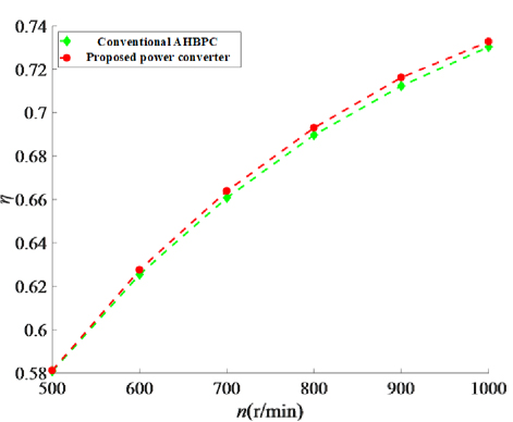
Figure 15: Comparison of system torque ripple when using conventional AHBPC and proposed power converter.
In Fig. 15, the torque ripple curve with conventional AHBPC is shown as a green dash line, while the torque ripple curve with proposed power converter is shown as a red dash line. When the rotor speed is between 500 r/min and 600 r/min, the torque ripple coefficient using the proposed power converter is slightly larger than that using the conventional AHBPC. However, as the speed increases from 700 r/min to 1000 r/min, the torque ripple coefficient using the proposed power converter becomes lower, and reaches its lowest at the speed of 900 r/min. Thus, in high-speed operation, the system torque ripple can be reduced by using proposed power converter, which is more conducive to the stable operation of the system.
Figure 16 shows a comparison of system efficiency in the case of using conventional AHBPC and the proposed power converter, where the proposed power converter is powered by a battery independently. The battery and PV cell of proposed power converter are both 12 V. The turn-on angle is set as 5∘, the turn-off angle is set as 25∘, and the load torque is set as 0.3 Nm.
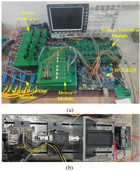
Figure 16: Comparison of system efficiency when using a conventional AHBPC and the proposed power converter.
The system efficiency curve with conventional AHBPC is shown as a green dash line, while the system efficiency curve with proposed power converter is shown as a red dash line in Fig. 16. As can be seen from Fig. 16, the system efficiency using the proposed power converter is higher than that using conventional AHBPC. Therefore, compared with the conventional AHBPC, the proposed power converter can reduce energy consumption to a greater extent, which is conducive to cost saving and environmental protection.
IV. EXPERIMENTAL VERIFICATION
To verify the feasibility of the proposed solution, a four-phase 8/6 SRM system with proposed power converter is employed for proof-of-concept. A photograph of our experimental platform is shown in Fig. 17. Key components of the experimental platform are listed in Table 2. Key sensors are listed in Table 3.
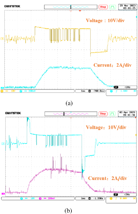
Figure 17: Photograph of the experimental platform: (a) experimental platform of SRM system and (b) 8/6 SRM.
Figure 18 shows the experimental results comparison of the voltage and current waveforms of the A-phase winding in the SRM system in the case of using conventional AHBPC and the proposed power converter. In the experiment, the rotor speed is set as 600 r/min; the turn-on angle is set as 5∘, and the turn-off angle is set as 20∘. The conventional AHBPC is powered by a battery, while the proposed power converter is powered by a PV cell.
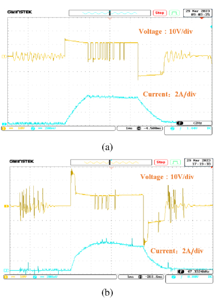
Figure 18: Comparison of experimental results: (a) voltage and current waveform with conventional AHBPC and (b) voltage and current waveform with proposed power converter.
Table 3: Key sensors of the SRM system
| Sensor | Type |
| DSP | TMS320F28335 |
| Core of the drive circuit | TLP250 |
| Current sensors | LA55P |
| Position sensor | GK152 (resolution 7.5∘) |
| Voltage sensors | AD7895 |
As shown in Fig. 18, the excitation voltage and demagnetization voltage of the A-phase winding with the conventional AHBPC are both the 12 V power supply voltage, which makes the excitation and demagnetization processes relatively slow and may cause negative torque and other problems, which is not conducive to the stable operation of the SRM system. By comparison, the excitation voltage and demagnetization voltage of the A-phase winding with the proposed power converter can reach up to 24 V, which can shorten the excitation and demagnetization processes.
In order to compare the performance of the SRM system at higher speeds when using two power converters in this paper, the initial 600 r/min was gradually increased to 1000 r/min in the experiment, while other parameters remained unchanged. Figures 19–22 show the experimental results comparison of voltage and current waveforms of the A-phase winding in the SRM system at higher speeds when both the conventional AHBPC and the proposed power converter are powered by battery independently.
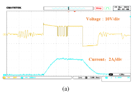
Figure 19: Experimental results comparison with two power converters when rotor speed is 700 r/min: (a) voltage and current waveform with conventional AHBPC and (b) voltage and current waveform with proposed power converter.
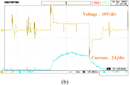
Figure 20: Experimental results comparison with two power converters when rotor speed is 800 r/min: (a) voltage and current waveform with conventional AHBPC and (b) voltage and current waveform with proposed power converter.
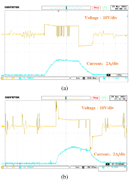
Figure 21: Experimental results comparison with two power converters when rotor speed is 900 r/min: (a) voltage and current waveform with conventional AHBPC and (b) voltage and current waveform with proposed power converter.
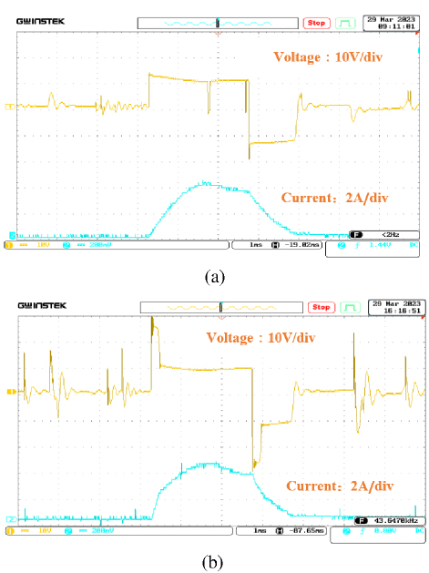
Figure 22: Experimental results comparison with two power converters when rotor speed is 1000 r/min: (a) voltage and current waveform with conventional AHBPC and (b) voltage and current waveform with proposed power converter.
It can be seen from Figs.19–22, at higher speeds, fast excitation and demagnetization can still be achieved with the proposed power converter. Even though the excitation and demagnetization velocities of the winding phase current gradually decrease due to the increase in rotor speed, high-level excitation and demagnetization greatly quicken the excitation and demagnetization processes. The performance improvement of the SRM system using the proposed power converter is more significant at high rotor speeds.
V. CONCLUSION
In this paper, a dual-source three-level power converter is proposed to be applied in a multi-port low-carbon building microgrid system. The front-end circuit of the proposed power converter is designed for switching between three power supply modes. Owing to the front-end circuit, the proposed power converter can achieve excitation and demagnetization at high levels, accelerate the excitation and demagnetization speed, and improve the efficiency of the SRM system. Although the excitation and demagnetization processes in dual-source power supply mode (mode 1) are similar to those of the conventional AHBPC, the system performance is improved in the other two working modes, which is verified in both simulation and experimental results.
ACKNOWLEDGMENT
This work was funded in part by National Natural Science Foundation of China under Grant 51967013 and in part by Natural Science Foundation of Jiangxi Province under Grant 20212BAB214061.
REFERENCES
[1] X. Liu, X. Liu, Y. Jiang, T. Zhang, and B. Hao, “Photovoltaics and energy storage integrated flexible direct current distribution systems of buildings: Definition, technology review, and application,” CSEE Journal of Power and Energy Systems, vol. 9, no. 3, pp. 829-845, May 2023.
[2] H. Shin and K. Lee, “Optimal design of a 1-kW switched reluctance generator for wind power systems using a genetic algorithm,” IET Electric Power Applications, vol. 10, no. 8, pp. 807-817, Sep. 2016.
[3] X. Xue, K. Cheng, J. Lin, Z. Zhang, K. Luk, T. Ng, and N. Cheung, “Optimal control method of motoring operation for SRM drives in electric vehicles,” IEEE Trans. Veh. Technol., vol. 59, no. 3, pp. 1191-1204, Mar. 2010.
[4] M. Michon, S. Calverley, and K. Atallah, “Operating strategies of switched reluctance machines for exhaust gas energy recovery systems,” IEEE Trans. Ind. Appl., vol. 48, no. 5, pp. 1478-1486, Sep./Oct. 2012.
[5] H. Chen and J. J. Gu, “Implementation of three-phase switched reluctance machine system for motors and generators,” IEEE/ASME Transactions on Mechatronics, vol. 15, no. 3, pp. 421-432, June 2010.
[6] R. Krishnan, S.-Y. Park, and K. Ha, “Theory and operation of a four-quadrant switched reluctance motor drive with a single controllable switch-the lowest cost four-quadrant brushless motor drive,” IEEE Transactions on Industry Applications, vol. 41, no. 4, pp. 1047-1055, July-Aug. 2005.
[7] J. Ye, B. Bilgin, and A. Emadi, “Comparative evaluation of power converters for 6/4 and 6/10 switched reluctance machines,” in IEEE Transportation Electrification Conference and Expo (ITEC), pp. 1-6, 2012.
[8] H.-C. Chang and C.-M. Liaw, “Development of a compact switched-reluctance motor drive for EV propulsion with voltage-boosting and PFC charging capabilities,” IEEE Transactions on Vehicular Technology, vol. 58, no. 7, pp. 3198-3215, Sep. 2009.
[9] D.-H. Lee and J.-W. Ahn, “A novel four-level converter and instantaneous switching angle detector for high speed SRM drive,” IEEE Transactions on Power Electronics, vol. 22, no. 5, pp. 2034-2041, Sep. 2007.
[10] K. Miyane and K. Akatsu, “High voltage driving method by using low voltage inverters for SRM,” in 2015 IEEE International Electric Machines & Drives Conference (IEMDC), Coeur d’Alene, ID, USA, pp. 335-339, 2015.
[11] C. Gan, Q. Sun, J. Wu, W. Kong, C. Shi, and Y. Hu, “MMC-based SRM drives with decentralized battery energy storage system for hybrid electric vehicles,” IEEE Transactions on Power Electronics, vol. 34, no. 3, pp. 2608-2621, Mar. 2019.
[12] P. Palanivel and S. S. Dash, “Multicarrier pulse width modulation methods based three phase cascaded multilevel inverter including over modulation and low modulation indices,” in TENCON 2009 - 2009 IEEE Region 10 Conference, Singapore, 2009.
[13] R. S. Alishah, K. Bertilsson, F. Blaabjerg, M. A. J. Sathik, and A. Y. Rezaee, “New grid-connected multilevel boost converter topology with inherent capacitors voltage balancing using model predictive controller,” in 2020 22nd European Conference on Power Electronics and Applications (EPE’20 ECCE Europe), Lyon, France, pp. 1-7, 2020.
[14] J. Borecki and B. Orlik, “Novel, multilevel converter topology for fault-tolerant operation of switched reluctance machines,” in 2017 11th IEEE International Conference on Compatibility, Power Electronics and Power Engineering (CPE-POWERENG), Cadiz, Spain, pp. 375-380, 2017.
[15] V. F. Pires, D. Foito, A. J. Pires, A. Cordeiro, and J. F. Martins, “An 8/6 SRM drive with a multilevel topology based on a cross-switched configuration,” in 2020 IEEE 14th International Conference on Compatibility, Power Electronics and Power Engineering (CPE-POWERENG), Setubal, Portugal, pp. 63-68, 2020.
[16] P. Azer, J. Ye, and A. Emadi, “Advanced fault-tolerant control strategy for switched reluctance motor drives,” in 2018 IEEE Transportation Electrification Conference and Expo (ITEC), Long Beach, CA, USA, pp. 20-25, 2018.
[17] V. Fernão Pires, A. Cordeiro, D. Foito, A. J. Pires, J. Martins, and H. Chen, “A multilevel fault-tolerant power converter for a switched reluctance machine drive,” IEEE Access, vol. 8, pp. 21917-21931, 2020.
[18] A. Cordeiro, V. F. Pires, A. J. Pires, J. F. Martins, and H. Chen, “Fault-tolerant voltage-source-inverters for switched reluctance motor drives,” in 2019 IEEE 13th International Conference on Compatibility, Power Electronics and Power Engineering (CPE-POWERENG), Sonderborg, Denmark, pp. 1-6, 2019.
BIOGRAPHIES

Cheng Liu received the B.S. degree in measurement control technology and instrument from Harbin Engineering University, Heilongjiang, China, in 2003, and the M.S. degree in information technology from University of Abertay Dundee (now Abertay University), Dundee, Scotland, in 2006, and is currently working toward the Ph.D. degree at the School of Information Engineering, Nanchang University, Nanchang, China. He is a Lecturer with the School of Advanced Manufacturing, Nanchang University, Nanchang, China. His research interests include renewable energy generations, micro-grids, motor control and multi-agent.

Yu Zhao received the B.S. degree in electrical engineering and automation from Shandong University of Science and Technology, Shandong, China, in 2019, and the M.S. degree in Electrical Engineering from Nanchang University, Nanchang, China, in 2023. He is currently working as a member in the power supply service team at Daishan County Power Supply Company of State Grid Zhejiang Electric Power Co. Ltd., Daishan, China. His research interests include switched reluctance motors and itscontrol.

Qing Wang received the B.S. degree in automation from Northeastern University, Shenyang, China, in 2011, and the Ph.D. degree in electrical engineering from China University of Mining and Technology, Xuzhou, China, in 2017. In 2018, he became a Lecturer with the School of Information Engineering, Nanchang University, Nanchang, China, where he has been an Associate Professor since 2023. His research interests include electric vehicles, electrical motor drives, renewable energy generations, and micro-grids.

Xiaofeng Wan received the B.S. degree in automation from Zhejiang University, Hangzhou, China, in 1994. She became a Lecturer with the School of Information Engineering, Nanchang University, Nanchang, China, where she has been a Professor since 2006. Her research interests include electric vehicles, renewable energy generations, and micro-grids.

Lei Cao received the B.S. degree in law from Nanchang University, Nanchang, China, in 2010. He is currently working at the Architecture Experimental Center of the Architecture and Design College at Nanchang University, Nanchang, China, with the title of Experimental Engineer. His research interests include building electricity and complex system modeling.
ACES JOURNAL, Vol. 40, No. 9, 900–912
doi: 10.13052/2024.ACES.J.400911
© 2025 River Publishers