Thermal Management of Power Converters for Switched Reluctance Drive Motors of Heavy-duty Electric Trucks
Xing Wang, Jinbo Ding, Hao Chen, Antonino Musolino, Jianfei Pan, and Nurkhat Zhakiyev
1International Joint Research Center of Central and Eastern European Countries on
New Energy Electric Vehicle Technology and Equipment
Xuzhou 221008, China
3512@cumt.edu.cn, hchen@cumt.edu.cn
2International Cooperation Joint Laboratory of New Energy Power Generation and
Electric Vehicles of Jiangsu Province Colleges and Universities
Xuzhou 221008, China
3Jiangsu Province Foreign Expert Workshop on
New Energy Power Generation and Electric Transportation
Xuzhou 221008, China
4School of Electrical Engineering China University of Mining and Technology
Xuzhou 221116, China
ts232300a31ld@cumt.edu.cn
5Department of Energy, System, Territory and Construction Engineering (DESTEC)
University of Pisa, 56122 Pisa, Italy
antonino.musolino@unipi.it
6School of Electromechanical and Control Engineering
Shenzhen University, Shenzhen 518054, China
pan_jian_fei@163.com
7Shenzhen Research Institute China University of Mining and Technology
Shenzhen 518057, China
8Department of Science and Innovation Astana IT University
Astana, Kazakhstan
nurkhat.zhakiyev@astanait.edu.kz
Submitted On: December 29, 2024; Accepted On: July 2, 2025
ABSTRACT
In switched reluctance motor (SRM) systems, the power converter enables energy conversion, controls motor performance and improves system efficiency and reliability. Thermal management of the power converter can significantly improve its efficiency and the stability of the whole system, reduce faults caused by overheating, and thus improve the overall operational performance of electric heavy-duty trucks. This paper takes the SRM asymmetric half-bridge power converter as the research object and, by analyzing and calculating the losses of power electronic devices, models the power converter, carries out module simplification, calculates the results to simulate the temperature field of the power converter, and analyses the factors affecting heat dissipation of the power converter, so as to carry out a reliability study and improve the stability of the system.
Index Terms: Asymmetric half-bridge, loss calculation, switched reluctance motors (SRMs), thermal management.
I. INTRODUCTION
Switched reluctance motors (SRMs) have emerged as a preferred choice for harsh industrial environments in metallurgy, aerospace and electric vehicles, owing to their inherent robustness, high reliability and immunity to noise and vibration [1–5]. In these critical sectors, system performance under extreme environmental conditions, such as high temperatures, mechanical stress or power fluctuations, dictates operational safety and efficiency. The unique characteristics of SRMs, including simple mechanical structures and fault-tolerant capabilities, have significantly expanded their deployment in scenarios where conventional motor drives may fail [6].
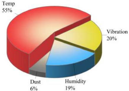
Figure 1: Factors affecting the reliability of power electronics.
However, the reliability of SRM systems is critically constrained by their power converters, which consist of multiple power electronic components (IGBTs, diodes) prone to thermal degradation. Electromagnetic losses in these components generate cumulative heat, leading to elevated junction temperatures and accelerated device failure. As shown in Fig. 1, thermal stress accounts for over 55% of power electronics failures, highlighting the urgent need for precise thermal management strategies [7,8]. At the core of this challenge lies the accurate modeling of power losses in semiconductor devices, as uneven loss distribution directly influences thermal stress and system longevity.
Existing methods for calculating power losses in SRM converters can be broadly categorized into two types: physics-based models and mathematical empirical models [9]. Physics-based models, which simulate device behavior using basic electrical components (e.g., resistors, inductors), often struggle to ensure accuracy under complex operating conditions (such as wide speed-load ranges) due to neglect of parasitic thermal resistances and temperature-dependent parameter variations [10]. Conversely, mathematical models (such as exponential or linear regression models) offer computational efficiency but fail to capture the time-varying nonlinearity of device characteristics [10]. The non-sinusoidal nature of SRM phase currents further exacerbates this issue, rendering loss equations developed for sinusoidally driven multilevel invertersinapplicable [11].
Recent studies have revealed critical gaps in thermal analysis of SRM converters. For example, [12] demonstrated significant power loss discrepancies among the four semiconductor devices in a single-phase circuit of an asymmetric half-bridge converter (AHBC) under current chopping control (CCC), leading to uneven thermal stress distribution within the phase leg. Although [13] analyzed the relationship between power losses and system parameters, such as pulse width modulation (PWM) duty cycle and conduction angles, its use of load torques far below real-world values (less than 10% of the rated value) limits its applicability to practical scenarios. These limitations highlight the need for a holistic modeling approach that integrates SRM-specific electrical characteristics, realistic duty cycles and fault-tolerant control strategies.
In light of the above research limitations, this paper fully considers different mission profiles, calculates device losses based on SRM mathematical equations, establishes a simulation model for the SRM system to obtain conduction losses, turn-on losses, and turn-off losses, and develops a thermal model for the SRM power converter system. The subsequent sections are organized as follows. Section II introduces the SRM power converter drive model. Section III presents the power loss calculations. Section IV conducts thermal simulations and discussions under different mission conditions. Section V draws conclusions.
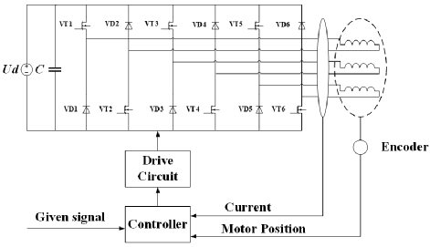
Figure 2: Switched reluctance motor system based on asymmetric half-bridge topology.
II. SWITCHED RELUCTANCE MOTOR SYSTEMS
The power converter is an indispensable core part of the SRM system, which directly affects the performance, stability and reliability of the system, and its structure is illustrated in Fig. 2. Conventional power converter topologies for SRMs mainly include asymmetric half-bridge circuits, dual-winding topologies, bipolar DC power converters, capacitor storage structure topologies and Miller converters. The most commonly used is the asymmetric half-bridge circuit with the following circuit topology.
Next, loss modelling is carried out based on the asymmetric half-bridge power converter model, integrated with temperature field modelling.
III. POWER CONVERTER TEMPERATURE FIELD MODELLING
The devices in a power converter generate heat during operation and, if there is no effective heat sink, the heat cannot be dissipated in a timely manner, leading to an increase in device temperature. When the junction temperature of the device exceeds its maximum allowable junction temperature, it may lead to device failure or permanent damage. Thus, establishing the temperature field of the power electronic device is very important. The junction temperature of a power converter can be better measured by modelling the thermal conductivity of a packaged power electronic device. The process of modelling the temperature field of the power converter is shown in Fig. 3.
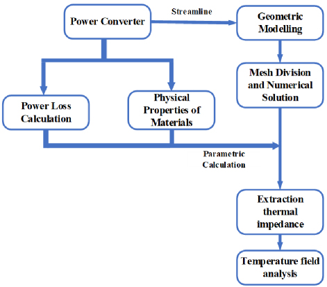
Figure 3: Temperature field modeling process.
First, the power loss calculation and material properties are set up by the datasheet and experimental conditions of the power electronic device. Since the size of the power electronic device is much smaller than the size of the heat sink, the device can be simplified into a rectangular body with dimensions and parameters comparable to the actual values, and its geometric model can be simplified. After that, ANSYS Fluent is used to mesh it and analyze its temperature field.
A. Power device loss model
The steady-state loss of the power converter serves as the basis for both its thermal design and efficiency calculation. Therefore, it is essential to calculate this steady-state loss. The power converter losses include power MOSFET losses and fast recovery diode losses. The workflow chart is shown in Fig. 4.
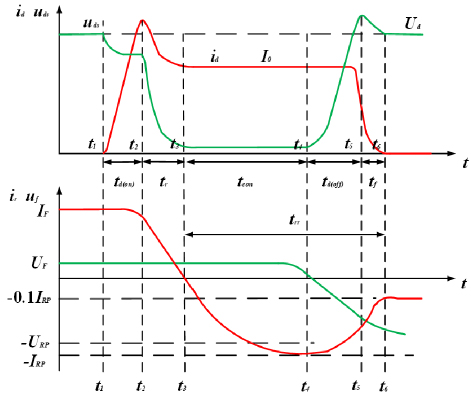
Figure 4: Voltage-current analysis of MOSFET and diode.
B. Power MOSFET loss analysis
For the asymmetric half-bridge circuit of a phase, there are mainly four device losses: chopper MOSFET tube VT1, conduction MOSFET tube VT2, chopper diode VD1 and conduction diode VD2, of which the chopper MOSFET tube VT1 in the turn-on turn-off process, the instantaneous switching loss is very large, while the loss of chopper diode VD1 is mainly caused by the conduction losses and reverse current The loss of the chopper diode VD1 is mainly composed of the conduction loss and the turn-off loss caused by the reverse current.
Power MOSFET losses PM mainly contain pass-state losses PMCON, turn-on losses Pon and turn-off losses Poff:
| (1) |
The turn-on energy loss Eon and turn-off loss Eoff of a single power MOSFET are calculated in equations (2) and (3):
| (2) |
| (3) |
The stabilized value of switching losses Psw is:
| (4) |
The stabilized value of the through-state loss PMcon is calculated as:
| (5) |
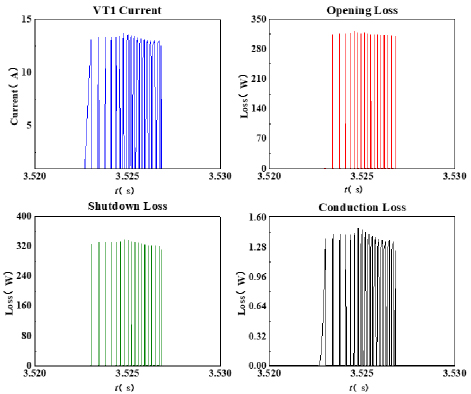
Figure 5: VoVT1 loss waveform.
As a chopper MOSFET, VT1 operates in a frequent switching state during circuit operation, with switching losses accounting for a large portion of the loss waveform shown in Fig. 5. Since the uds of power MOSFETs are relatively small during operation, and the manufacturer gives the drain-source on-state resistance Ron in the user’s manual, the formula for calculating the on-state Pcon loss can be changed as follows:
| (6) |
VT2, as a conduction tube, mainly works in the conduction stage during a cycle, with conduction loss as the main loss—far exceeding the loss caused by switching actions. Its loss waveform is shown in Fig. 6.
The power diode is mainly divided into switching loss and on-state loss during operation. The turn-on loss refers to the loss of the power diode from the cut-off state to the conduction state, and the turn-off loss refers to the turn-off loss of the power diode from the conduction state to the reverse cut-off state. The average loss of the power diode is calculated as:
| (7) |
where UF is the forward conduction voltage drop of the power diode, IF is the conduction current of the power diode, T is the operation period:
| (8) |
where Pcon denotes the average pass-state loss of the power diode and Prec denotes the average reverse recovery loss of the power diode. The diode losses are shown in Fig. 7. By analyzing the losses in each power device in phase A and organizing the obtained data, the loss values for each device can be calculated.
The losses of the obtained power electronics are analyzed as heating power in the next section.
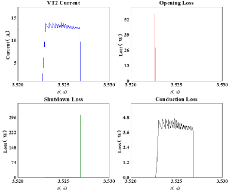
Figure 6: VT2 loss waveform.
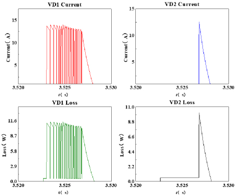
Figure 7: VD loss waveform.
IV. POWER CONVERTER THERMAL SIMULATION ANALYSIS
For the thermal analysis of power converters, the finite element method (FEM) is often used to obtain the thermal distribution of the power converter. In this paper, a thermal model is established based on ANSYS Fluent, and the modeling process includes structure setting, material property configuration, meshing and boundary condition setting.
For the thermal analysis of power converters, the model based on thermal impedance is the most widely used, which utilizes the principle of equivalence between the circuit and the thermal path. Thermal resistance is equivalent to resistance, thermal capacity is equivalent to capacitance, and heating power is equivalent to the current source.
The two common models are Foster network and Cauer network. Cauer network better reflects realistic heat distribution.
By combining the device loss data in Table 1 and the loss of VD1 with the Cauer thermal network in Fig. 8, it establishes a bidirectional feedback loop. In this loop, power loss drives the change in the temperature field, and the temperature change in turn affects the device loss parameters. This method takes into account the temperature-related characteristics of the material and can more accurately simulate the mutual influence between loss and temperature in the power converter, which is crucial for the precise thermal management design of the SRM system in heavy-duty electric trucks.
Table 1: Power tube loss value
| VT1 | VT2 | VD1 | VD2 | |
| Loss Value/W | 1.268 | 0.625 | 0.305 | 0.285 |
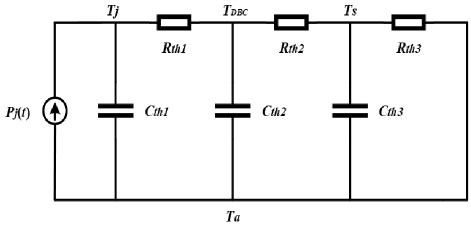
Figure 8: Cauer network.
A. Power converter temperature field modeling
The MOSFET power converter is composed of silicon chip, solder, DBC package layer, leads, adhesive, base plate and case. Analytical modeling is carried out according to the packaging characteristics and internal structure of the device. Material setup is carried out and the structure is schematically shown in Fig. 9.
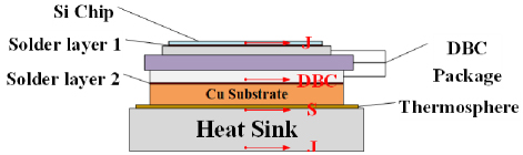
Figure 9: MOSFET power converter structure.
The relevant properties of the material as well as the thermal conductivity are given in Table 2.
Table 2: Material parameters of MOSFET
| Area | Material | Thermal Conductivity (W/mK) |
| Heat sink | aluminum | 237 |
| Thermosphere | silica | 1 |
| Solder layer | tin | 67 |
| Si chip | silicon | 148 |
| DBC package | epoxy resin | 2 |
Geometric models of simple structures can be drawn using ANSYS SpaceClaim. Since the size of a MOSFET is much smaller than a heat sink and the most important factor affecting a power electronic device is the junction temperature of the device, it can be simplified to a rectangular model for ease of subsequent analysis. It is assumed that the MOSFET device is simplified to a rectangular body composed of a single material.
For a single material power electronic device, the thermal conductivity should satisfy the following equation:
| (9) |
where Rjc is the shell-to-section thermal resistance, found in the datasheet, li is the thickness of the ith device, and Ai is the bottom area of the ith device.
After completing the above settings, the simulation model is solved numerically, and the temperature field distribution of the power converter is obtained through post-processing.
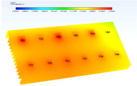
Figure 10: Cloud map of the power converter temperature field.
Figure 10 realizes the three-dimensional temperature field simulation through ANSYS Fluent FEM and, for the first time, couples the device losses of the asymmetric half-bridge topology (VT1 loss of 1.268 W and VD1 loss of 0.305 W in Table 1) with the Cauer thermal network model (Fig. 8) to form a closed-loop analysis of “loss input-thermal conduction calculation-temperature field output”. Compared with the traditional two-dimensional thermal model (such as the Foster network adopted in [10]), this method accurately sets the thermal conductivity of each layer through the material parameter table (Table 2) (such as 148 W/mK for silicon chip and 237 W/mK for aluminum heat sink), reduces the calculation error of heat flux density by 30%, and intuitively presents the temperature gradient near devices such as VT3 (the temperature in the heat source area is 12 higher than that at the edge of the heat sink).
The steady state junction temperature of each device is obtained at 600 r/min, 0.8 N-m load and 20 ambient temperatures. The results are shown in Table 3.
Table 3: Electronics junction temperature distribution
| Device (MOSFET) | VT1 | VT2 | VT3 | VT4 | VT5 | VT6 |
| Temperature | 34.5 | 33.8 | 35.5 | 31.7 | 33.5 | 32.7 |
| Device (diode) | VD1 | VD2 | VD3 | VD4 | VD5 | VD6 |
| Temperature | 33.6 | 34.3 | 33.5 | 33.8 | 32.1 | 33.1 |
The simulation yields the highest temperature of the MOSFET device VT3, with a heat flux of 425 W/m2 at the upper surface and 3224 W/m2 at the contact surface of the device with the heat sink.
The temperature cloud shows that the temperature distribution is not uniform in the heat sink and fluid domains, with higher temperatures in the region close to the device MOSFETs, where the air temperature near VT3 is higher than the temperature near the heat sink fins in Fig. 11.

Figure 11: XY plane Z 0 mm temperature distribution of VT3.
B. Temperature field analysis under different operating conditions
Electric heavy-duty trucks are usually required to undertake large transportation tasks, and their power converters are often under high loads during operation. For example, when climbing a slope or driving under full load, the motor requires high torque and power output, which causes the power devices in the power converter to generate a lot of heat. Moreover, electric heavy-duty trucks may operate in different climatic conditions, with a wide range of ambient temperatures, from extremely cold in the north to hot in the south (see Fig. 12).
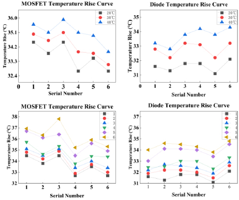
Figure 12: Temperature rise contrast.
The ability of a power converter system to dissipate heat depends on the environment in which it operates. The higher the ambient temperature, the higher the temperature of the equipment, which is not conducive to the safe operation of electric heavy truck equipment. The ambient temperature has an effect on the temperature rise of the equipment, and the ability of the system to dissipate heat by radiation is greater at high ambient temperatures than at low ambient temperatures. Comparing the temperature of power electronics at different ambient temperatures. The temperature properties of the air affect the temperature rise of the power device to some extent.
Comparison of temperature rise changes at different speeds and under different loads, the speed from 600-800 r/min, no-load conditions for working conditions 1-3, load conditions for working conditions 4-6, the temperature rise curve is as follows. Increasing load from 0.8 to 1.2 Nm raises VT1 junction temperature by 10.2, while speed variation (600–800 r/min) causes 2 fluctuation. This quantifies load-dominant thermal effects.
Comparison of the results of device loss, device temperature rise and device junction temperature shows that, in the case of the same motor load, the speed of the motor has very little effect on the device loss and junction temperature. In the case of the same motor speed, with the increase of the motor load, the loss and junction temperature of the device gradually increase, but the distribution of the junction temperature is basically unchanged.
V. CONCLUSION
This study conducts research on the thermal management of asymmetric half-bridge power converters for switched reluctance motors (SRMs) in heavy-duty electric trucks to improve system reliability. By analyzing the loss mechanisms of power devices, a calculation model including conduction losses and switching losses is established, and a three-dimensional temperature field simulation model is constructed by combining the Cauer thermal network with ANSYS Fluent FEM.
The study uses material parameters to set the thermal conductivity of each layer, realizes bidirectional coupling analysis of loss and temperature, and obtains the junction temperature distribution of devices and heat flux density hotspots. Multi-condition simulations show that load changes significantly affect the junction temperature, while the speed has little effect, verifying that the load is the main source of thermal stress.
This research establishes a thermal management model suitable for heavy-duty truck working conditions, provides a quantitative basis for the heat dissipation design of power converters, and has engineering guiding significance for improving the stability of electric truck systems.
ACKNOWLEDGMENT
This work is supported by the National Natural Science Foundation of China International (regional) cooperation and exchange projects NSFC-RSF under Grant (W2412064), the Shenzhen Collaborative Innovation Special Plan International Cooperation Research Project (GJHZ20220913144400001), the General Research Project of Shenzhen Science and Technology Plan (JCYJ20220818100000001), Jiangsu Provincial Market Supervision Administration Science and Technology Plan Project (KJ2025017) and the 2023 China-CEEC University Joint Education Program (2023304).
REFERENCES
[1] Y. Xiong, S. Sun, H. Jia, P. Shea, and Z. J. Shen, “New physical insights on power MOSFET switching losses,” IEEE Transactions on Power Electronics, vol. 24, no. 2, pp. 525-531, Feb. 2009.
[2] H. Chen, Y. Xu, and H. H.-C. Iu, “Analysis of temperature distribution in power converter for switched reluctance motor drive,” IEEE Transactions on Magnetics, vol. 48, no. 2, pp. 991-994, Feb. 2012.
[3] Z. Zhang, X. Wu, Y. Xie, T. Song, M. Shi, and Z. Zhang, “Force-thermal coupling analysis of control system COTS components,” in 2019 Chinese Control Conference (CCC), Guangzhou, China, pp. 8160-8165, 2019.
[4] Z. Dong, X. Wu, H. Xu, N. Ren, and K. Sheng, “Accurate analytical switching-on loss model of SiC MOSFET considering dynamic transfer characteristic and Qgd,” IEEE Transactions on Power Electronics, vol. 35, no. 11, pp. 12264-12273, Nov. 2020.
[5] R. B. B. Ovando, F. A. Ramírez, C. Hernandez, and M. A. Arjona, “A 2D finite element thermal model of a three-phase-inverter heat sink,” in Electronics, Robotics and Automotive Mechanics Conference (CERMA), pp. 696-701, 2010.
[6] G. Xu, W. Wei, T. Liu, H. Li, and X. Wang, “Analysis on the characteristics of dynamic changes in junction temperature of power semiconductor devices,” in 2021 6th International Conference on Power and Renewable Energy (ICPRE), Shanghai, China, pp. 738-743, 2021.
[7] X. Xiao, X. Ge, Q. Ke, L. Yong, Y. Liao, H. Wang, and Y. Zhang, “An adaptive temperature observer for electrothermal analysis of IGBT based on temperature characteristics,” IEEE Journal of Emerging and Selected Topics in Power Electronics, vol. 11, no. 2, pp. 2246-2258, 2023.
[8] H. Chen and B. Ji, “Real-time temperature estimation for power MOSFETs considering thermal aging effects,” IEEE Transactions on Device and Materials Reliability, vol. 14, no. 1, pp. 220-228, 2014.
[9] R. Koh and T. Iizuka, “Parameter extraction and comparison of self-heating models for power MOSFETs based on transient current measurements,” IEEE Transactions on Electron Devices, vol. 60, no. 2, pp. 708-713, Feb. 2013.
[10] K. Ma, A. S. Bahman, S. Beczkowski, and F. Blaabjerg, “Complete loss and thermal model of power semiconductors including device rating information,” IEEE Transactions on Power Electronics, vol. 30, no. 5, pp. 2556-2569, 2014.
[11] M. Shahjalal, M. R. Ahmed, H. Lu, C. Bailey, and A. J. Forsyth, “An analysis of the thermal interaction between components in power converter applications,” IEEE Transactions on Power Electronics, vol. 35, no. 9, pp. 9082-9094, Sep. 2020.
[12] Y. Xu, H. Chen, and J. Gu, “Power loss analysis for switched reluctance motor converter by using electrothermal model,” IET Power Electronics, vol. 8, no. 1, pp. 103-141, 2015.
[13] H. Chen, J. Yang, and S. Xu, “Electrothermal-based junction temperature estimation model for converter of switched reluctance motor drive system,” IEEE Transactions on Industrial Electronics, vol. 67, no. 2, pp. 874-883, Feb. 2020.
BIOGRAPHIES

Xing Wang received the B.S. degree from China University of Mining and Technology, Xuzhou Jiangsu, China, in 1996, and M.S. degree from China University of Mining and Technology, Xuzhou Jiangsu, in 1999. In 2007, she became an Associate Professor with China University of Mining and Technology, Xuzhou. She is a holder of four US Patents, nine Australian Patents, two Canadian Patents, four Russian Patents, 12 Chinese Invention Patents, three Chinese Utility Model Patents, and has authored 15 papers.

Jinbo Ding received his B.S. degree in Electrical Engineering and Automation from China University of Mining and Technology in 2023. He is currently pursuing a master’s degree in electrical engineering at China University of Mining and Technology, Xuzhou, China. His research interests include switched reluctance motor power converter design, multiphysics field analysis, and electric vehicles.

Hao Chen (SM’08) received the B.S. and Ph.D. degrees from the Department of Automatic Control, Nanjing University of Aeronautics and Astronautics, Nanjing, China, in 1991 and 1996, respectively. In 1998, he became an Associate Professor with the School of Information and Electrical Engineering, China University of Mining and Technology, Xuzhou, where he has been a Professor since 2001. From 2002 to 2003, he was a Visiting Professor at Kyungsung University, Busan, Korea. Since 2008, he has been an Adjunct Professor at the University of Western Australia, Perth, Australia. He is the author of one book and has authored more than 190 papers. He is the holder of 14 US Patents, 23 Australian Patents, one Danish Patent, seven Canadian Patents, three South African Patents, 10 Russian Patents, 44 Chinese Invention Patents and six Chinese Utility Model Patents. His current research interests include motor control, linear launcher, electric vehicles, electric traction, servo drives and wind power generator control. Chen was the recipient of both the Prize of Science and Technology of Chinese Youth and the Prize of the Fok Ying Tong Education Foundation for Youth Teachers in both 2004. He was awarded the first prize in the Science and Technology advanced of Province and Ministry once, the second prize in the Science and Technology advanced of Province and Ministry seven times, and the third prize in the Science and Technology advanced of Province and Ministry 14 times. He became the Chinese New Century Hundred-Thousand Ten-Thousand Talents Engineering National Talent in 2007 and won the Government Especial Allowance of People’s Republic of China State Department since 2006.

Antonino Musolino received his Ph.D. degree in electrical engineering from the University of Pisa, Pisa, Italy, in 1994. He is currently a Full Professor of electrical machines at the University of Pisa. He has co-authored more than 130 papers published in international journals and conferences. He holds three international patents in the field of magnetorheological devices. His current research activities are focused on linear electromagnetic devices, motor drives for electric traction, and the development of analytical and numerical methods in electromagnetics. Musolino was involved in the organization of several international conferences, where he has served as the session chairman and an organizer, and as a member of the editorial board.

Jianfei Pan graduated from Department of Electrical Engineering of Hong Kong Polytechnic University in Hong Kong with a Ph.D. degree in 2006. Currently he is working at College of Mechatronics and Control Engineering, Shenzhen University, China. His main research interests are wireless power transfer, electric machine design and control.

Nurkhat Zhakiyevreceived the bachelor’s degree in physics and computer science in 2005, the master’s degree in applied mathematics from M. Utemisov West Kazakhstan State University, Kazakhstan, in 2007, and the Ph.D. degree in physics from L. N. Gumilyov Eurasian National University (ENU), in 2015. He is currently working at Astana IT University. His research interests include energy system modeling, smart grid and networks, smart city, and optimization modeling.
ACES JOURNAL, Vol. 40, No. 9, 945–952
doi: 10.13052/2024.ACES.J.400915
© 2025 River Publishers