Electromagnetic Characteristics Analysis of a Symmetrical-Stator Axial Flux Dual-Mechanical-ports Switched Reluctance Motor
Fengyuan Yu, Xing Wang, Hao Chen, Wenju Yan, Jianfei Pan, Popov Stanislav Olegovich, Bodrenkov Evgenii Alexandrovich, Nurkhat Zhakiyev,and Yassen Gorbounov
1School of Electrical Engineering
China University of Mining and Technology, Xuzhou 221116, China
fyyu@cumt.edu.cn, yanwenju09@126.com
*Corresponding author: hchen@cumt.edu.cn
2International Joint Research Center of Central and Eastern European Countries on
New Energy Electric Vehicle Technology and Equipment
Xuzhou 221008, China
3512@cumt.edu.cn
3Shenzhen Research Institute
China University of Mining and Technology, Shenzhen 518057, China
4School of Electromechanical and Control Engineering
Shenzhen University, Shenzhen 518054, China
pan_jian_fei@163.com
5Institute of Energy
Peter the Great Saint-Petersburg Polytechnic University
Saint Peters burg 195251, Russia
popovso@spbstu.ru, bodrenkovea@spbstu.ru
6Department of Science and Innovation
Astana IT University, Astana, Kazakhstan
nurkhat.zhakiyev@astanait.edu.kz
7Department of Informatics
New Bulgarian University, Sofia 1618, Bulgaria
y.gorbounov@mgu.bg
Submitted On: June 13, 2024; Accepted On: July 25, 2025
ABSTRACT
Dual-mechanical-ports motors, as a new motor type, have two mechanical ports that can operate independently or simultaneously. It has good application prospects in new energy generation and hybrid power systems with the advantages of compact structure and high integration. In this paper, a novel symmetrical-stator axial flux dual-mechanical-ports switched reluctance motor is proposed. The number of stator poles is 16, and the poles of the two rotors are 14 and 10, respectively. The three-dimensional finite element analysis model is built in Altair Flux software. The electromagnetic performance such as magnetic density, flux linkage, static torque, and decoupling characteristics are analyzed adopting the finite element analysis method. The results proved the effectiveness of the new motor structure.
Index Terms: Coupling characteristics, dual-mechanical-ports, electromagnetic performance, finite element analysis, switched reluctance motor.
I. INTRODUCTION
With the development of electrified transportation, new energy generation, and other emerging fields, the demand for dual-mechanical-ports motor systems is increasing and becoming a hot research direction [1–2]. For example, for hybrid vehicles, the drive system not only needs to realize the electromechanical energy conversion between the engine, the power battery, and the wheels, but also needs to regulate the energy between them to ensure that the engine operates in the optimal efficiency region. The Prius hybrid car produced by Toyota adopts a planetary gear-based drive system. This system enables power transmission and distribution between the engine, battery, and wheels in the hybrid system. However, the many mechanical components lead to reduced reliability of the whole system. In recent years, the two-mechanical-ports motor system has been proposed to achieve the same functionality of a planetary gear-based hybrid system with the advantages of good compactness, high integration, and synergistic output of multiple ports [3–4].
Different types of dual-mechanical-port motors such as permanent magnet synchronous, brushless DC, doubly fed, and magnetic field modulated motors have been investigated [5–9]. Switched reluctance motors, due to the absence of windings and permanent magnets in the rotor, have the advantages of robust construction and high fault tolerance. Few studies related to switched reluctance motors with dual-mechanical-ports have been reported. References [10–11] proposed a radial flux dual rotor switched reluctance motor structure. However, the outer rotor needs to be designed as a cup structure, which is not stable enough for operation. In addition, the radial flux motor cannot avoid the common drawbacks such as low utilization of space and low aspect ratio.
The axial flux motor structure has the flux direction perpendicular to the direction of rotation and the torque output capability is not affected by the axial length, which has the advantages of high torque density and short axial length. Reference [12] investigated a dual rotor axial flux switched reluctance motor and obtained high torque density. However, its two rotors are connected and jointly output mechanical power through one shaft. References [13–14] studied counter-rotating dual-rotor motors and analyzed their magnetic coupling characteristics.
A symmetrical-stator axial flux dual-mechanical-port switched reluctance motor (AFDMP-SRM) is proposed in this paper. The paper is arranged as follows. Motor topology is presented in section II. In section III, the finite element model of the motor is developed and the electromagnetic performance of two mechanical ports operating independently is analyzed. The electromagnetic performance of two mechanical ports operating simultaneously is analyzed in Section IV. Section V concludes the paper.
II. MOTOR STRUCTURE
The structure of a symmetrical-stator AFDMP-SRM is given in Fig. 1. The motor has a single stator and double rotor structure with two outer rotors set on either side of a single inner stator. Note that the single stator is a symmetrical structure with alternating wide and narrow tooth poles on both sides, and the stator poles share a common stator yoke. There are 16 stator poles on each side of the stator, divided into 8 wide poles and 8 narrow poles. The AFDMP-SRM is a dual four-phase motor. Both sets of windings are of a single-tooth winding structure, with windings 1 and 2 wound on the wide poles on both sides of the stator, and no winding on the narrow pole of the stator. Note that winding 1 contains four phases ABCD and winding 2 contains four phases EFGH. The pole number of Rotor1 and Rotor2 are 14 and 10, respectively. This provides the possibility that the two mechanical ports could have different rated speeds.
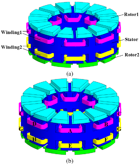
Figure 1: Diagram of the symmetrical-stator AFDMP-SRM structure: (a) overall view and (b) winding structure.
Table 1: Parameters of the symmetrical-stator AFDMP-SRM
| Motor Parameter | Item | Value |
| Stator poles number | / | 16 |
| Rotor1 poles number | / | 10 |
| Rotor2 poles number | / | 14 |
| Stator/rotor outer diameter | mm | 175 |
| Stator/rotor inner diameter | mm | 101 |
| Stator yoke thickness | mm | 16 |
| Stator poles length | mm | 15 |
| Stator pole shoes length | mm | 3 |
| Stator slot width | mm | 12 |
| Rotor1 pole length | mm | 6 |
| Rotor2 pole length | mm | 6 |
| Rotor1 pole shoes length | mm | 2 |
| Rotor2 pole shoes length | mm | 2 |
| Air-gap length | mm | 0.5 |
| Winding coil turns per pole | / | 50 |
As can be observed, the AFDMP-SRM does not employ the traditional solution of separating the two sides of the stator with a non-magnetic ring to avoid magnetic coupling of the two sets of windings. The motor is a combination of two single-stator, single-rotor motors by means of a shared stator yoke, which avoids the increase of the axial dimensions.
III. ELECTROMAGNETIC PERFORMANCE ANALYSIS OF TWO MECHANICAL PORTS OPERATING INDEPENDENTLY
To analyze the electromagnetic characteristics of the AFDMP-SRM, its three-dimensional analytical model is developed in finite element software Altair Flux. The B-H curve for 50DW470 material is illustrated in Fig. 2.
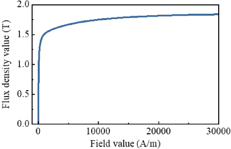
Figure 2: B-H curve of material 50DW470.
Firstly, the magnetic density characteristics of the motor are analyzed. Applying separate excitation currents to phase-A of winding 1 and phase-E of winding 2, the magnetic density cloud maps are presented in Figs. 3 and 4. From Fig. 3, it can be seen that when a 30 A current is applied to phase-A, mechanical port 1 forms a shorter flux path due to the wide and narrow stator poles, the segmented-rotor, and the single-tooth winding structure. In the Rotor1 aligned position, the magnetic density is more uniformly distributed in the stator yoke, the stator poles on the mechanical port side, and the Rotor1. In addition, the magnetic density has almost no value at phase-E stator pole and Rotor2.
Similarly, as can be seen in Fig. 4, at the Rotor2 aligned position, the magnetic density is more uniformly distributed in the stator yoke, the phase-E stator poles, and the Rotor2. Magnetic density has almost no value at phase-A stator poles and Rotor1.
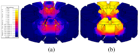
Figure 3: Magnetic density maps when phase-A is excited alone: (a) Rotor1 unalignment position and (b) Rotor1 alignment position.
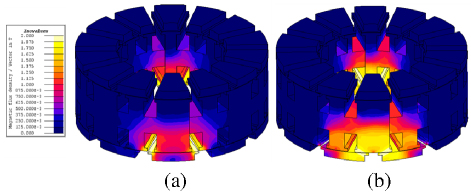
Figure 4: Magnetic density maps when phase-E is excited alone: (a) Rotor2 unalignment position and (b) Rotor2 alignment position.
Further, the static electromagnetic torque and flux linkage characteristics with the two mechanical ports of the AFDMP-SRM are analyzed. The electromagnetic torque of Rotor1 for half rotor cycle is obtained by applying an excitation current to the phase-A alone, as shown in Fig. 5 (a). Figure 5 (b) presents the electromagnetic torque of the Rotor2 when the current is applied to the phase-E alone. It should be noted that the horizontal axis of Figs. 5 (a) and (b) ranges from half rotor cycle, from the respective rotor unaligned position to the aligned position. They have the same electrical angle of 180∘, although the mechanical angle is different. For Rotor1, the mechanical angle of half rotor cycle is 360/10/2. The mechanical angle of half rotor cycle is 360/14/2 for Rotor2.
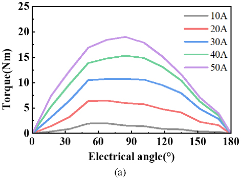
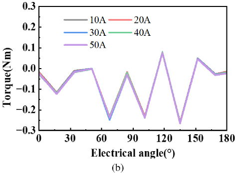
Figure 5: Static torque of two mechanical ports of AFDMP-SRM: (a) Rotor1 and (b) Rotor2.
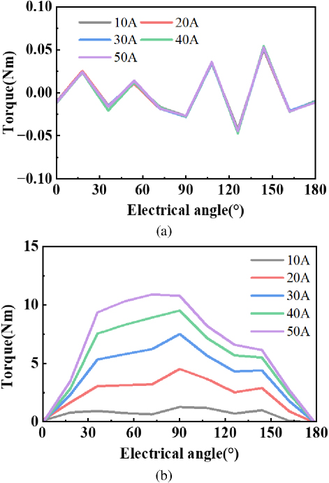
Figure 6: Static torque of two mechanical ports of AFDMP-SRM: (a) Rotor1 and (b) Rotor2.
As can be seen, the torque output capability of mechanical port 1 with a 16/10 poles configuration is higher than that of mechanical port 2 with a 16/14 poles configuration. Moreover, when the current is applied to the winding 1 alone, the Rotor1 outputs electromagnetic torque. The electromagnetic torque of the Rotor2 is quite small, not exceeding -0.3 Nm at 50 A. When the current is applied to the winding 2 alone, the Rotor2 outputs electromagnetic torque. The electromagnetic torque of the Rotor1 is small, not more than 0.1 Nm at 50 A. Therefore, by applying separate currents to the two sets of windings, a lesser effect on the other mechanical port could be detected. It is demonstrated that the electromagnetic coupling of the AFDMP-SRM to the other is not significant when the two mechanical ports are operated separately.
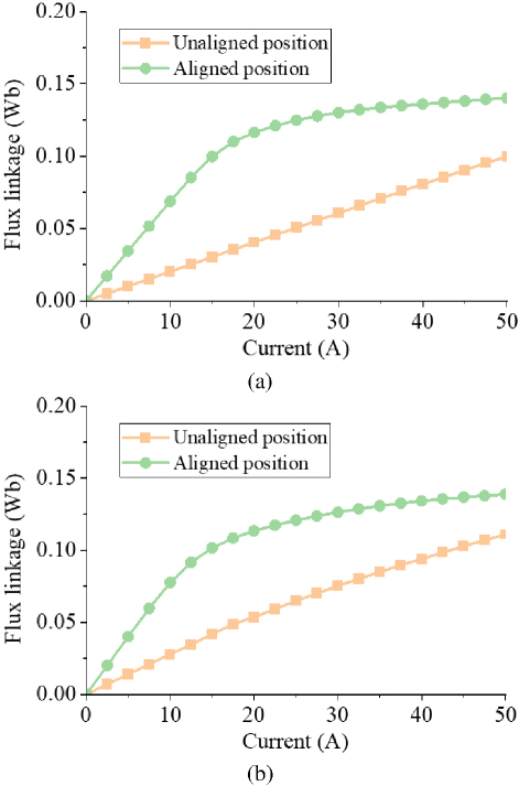
Figure 7: Flux linkage of two sets of winding of AFDMP-SRM: (a) flux linkage of phase-A and (b) flux linkage of phase-E.
Figure 7 shows the flux linkage waveforms of phase-A and phase-E when currents ranging from 0 A to 50 A are applied at the fully unaligned and aligned positions. It can be observed that the area enclosed by the magnetization curve of phase-E is smaller than that of phase-A. This indicates that, under the same magnetomotive force, the electromagnetic torque output capability of mechanical port 1 is greater than that of mechanical port 2.
IV. ELECTROMAGNETIC PERFORMANCE ANALYSIS OF TWO MECHANICAL PORTS OPERATING SIMULTANEOUSLY
Unlike the single-mechanical-port motor, the dual-mechanical-port motor can operate their two mechanical ports independently or simultaneously. In section III, the magnetic flux density characteristics of the motor during independent operation of the two mechanical ports are investigated. The magnetic flux density characteristics when both ports are operating simultaneously also need to be examined.
When exciting the coils of phase-A with winding 1 and phase-E with winding 2 simultaneously, the magnetic flux density characteristics of two rotors, with Rotor1 and Rotor2 in the unaligned position and the aligned position, are shown in Fig. 8.
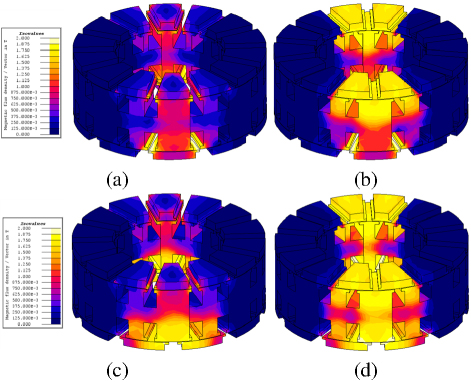
Figure 8: Magnetic density maps when phase-A and phase-E are excited simultaneously: (a) Rotor1 unalignment position and Rotor2 unalignment position, (b) Rotor1 alignment position and Rotor2 unalignment position, (c) Rotor1 unalignment position and Rotor2 unalignment position, and (d) Rotor1 alignment position and Rotor2 unalignment position.
By examining Figs. 3 and 4, it could be observed that when Rotor1 or Rotor2 operates independently, the impact on the magnetic flux density of the other port is minimal. However, from Fig. 8, it is difficult to directly observe the mutual influence between the two mechanical ports. To quantitatively analyze the magnetic coupling characteristics between the two mechanical ports, the magnetic flux linkage and inductance characteristics are further investigated.
It should be noted that the self-inductance coefficient is defined as the rate of change of the total flux linkage through that winding to the phase current, for a given rotor position angle and phase current [15–16].
| (1) |
where denotes the flux linkage of the phase winding. and i are the rotor position angle and phase current, respectively.
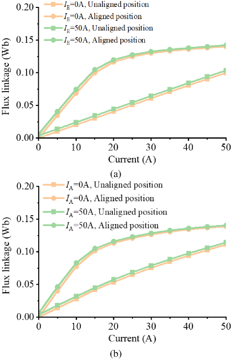
Figure 9: Flux linkage of two mechanical ports of AFDMP-SRM: (a) Rotor1 and (b) Rotor2.
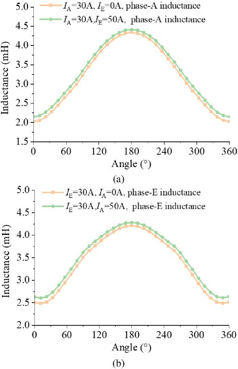
Figure 10: Inductance of two mechanical ports of AFDMP-SRM: (a) Rotor1 and (b) Rotor2.
From Fig. 9, it can be observed that, as the applied current of the winding on the other side increases from 0 A to 50 A, the flux linkage of phase-A at both the fully unaligned position and the aligned position slightly increases. The inductance characteristics shown in Fig. 10 also confirm that the phase inductance increases throughout the entire rotor cycle.
Table 2 lists the maximum and minimum inductance values of the phase-A winding when the current of the phase-E winding varies. Similarly, Table 3 presents the maximum and minimum inductance values of the phase-E winding when the current of the phase-A winding varies. It can be found that, at low current levels, the difference between the maximum and minimum inductance values is relatively large. However, as the current increases, the difference in inductance values decreases, which could be attributed to the electromagnetic saturation effect.
The maximum and minimum inductances refer to the peak and trough values of inductance observed over one rotor electrical cycle at a fixed current level. Generally, the maximum inductance Lmax corresponds to the inductance at the rotor aligned position, while the minimum inductance Lmin corresponds to the inductance at the rotor unaligned position.
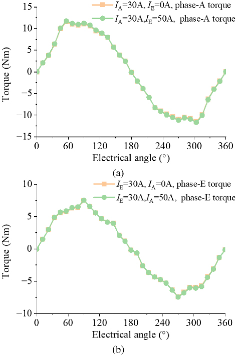
Figure 11: Static torque of two mechanical ports of AFDMP-SRM: (a) Rotor1 and (b) Rotor2.
Table 2: Influence of phase-E current on inductance of phase-A
| Lmin | Lmax | |||
| I 0 A | I 50 A | I 0 A | I 50 A | |
| I 10 A | 2.026 | 2.406 | 6.871 | 7.452 |
| I 20 A | 2.026 | 2.216 | 5.817 | 5.981 |
| I 30 A | 2.024 | 2.151 | 4.336 | 4.413 |
| I 40 A | 2.016 | 2.108 | 3.399 | 3.446 |
| I 50 A | 1.999 | 2.071 | 2.804 | 2.841 |
Table 3: Influence of phase-A current on inductance of phase-E
| Lmin | Lmax | |||
| I 0 A | I 50 A | I 0 A | I 50 A | |
| I 10 A | 2.789 | 3.177 | 7.755 | 8.300 |
| I 20 A | 2.678 | 2.869 | 5.667 | 5.799 |
| I 30 A | 2.507 | 2.629 | 4.212 | 4.283 |
| I 40 A | 2.351 | 2.440 | 3.355 | 3.397 |
| I 50 A | 2.219 | 2.286 | 2.778 | 2.808 |
Table 4: Influence of phase-E current on inductance difference and inductance variation rate of phase-A
| Lmax-Lmin | Lmax/Lmin | |||
| I 0 A | I 50 A | I 0 A | I 50 A | |
| I 10 A | 3.391 | 3.098 | 4.844 | 5.046 |
| I 20 A | 2.871 | 2.699 | 3.791 | 3.765 |
| I 30 A | 2.142 | 2.052 | 2.311 | 2.262 |
| I 40 A | 1.686 | 1.634 | 1.384 | 1.338 |
| I 50 A | 1.403 | 1.372 | 0.806 | 0.771 |
Table 5: Influence of phase-A current on inductance difference and inductance variation rate of phase-E
| Lmax-Lmin | Lmax/Lmin | |||
| I 0 A | I 50 A | I 0 A | I 50 A | |
| I 10 A | 2.781 | 2.612 | 4.966 | 5.123 |
| I 20 A | 2.116 | 2.022 | 2.989 | 2.930 |
| I 30 A | 1.680 | 1.629 | 1.706 | 1.654 |
| I 40 A | 1.427 | 1.392 | 1.005 | 0.957 |
| I 50 A | 1.252 | 1.229 | 0.559 | 0.523 |
From Tables 4 and 5, it could be observed that the differences and ratios between the maximum and minimum inductance values exhibit less variation compared to the variation in their absolute values.
Furthermore, Fig. 11 presents a comparison of the electromagnetic torque for Rotor1 and Rotor2 before and after applying current to the other side. It can be seen that the change in torque is not significant.
V. CONCLUSION
This paper proposes a novel 10/16/14 symmetrical-stator axial flux dual-mechanical-ports switched reluctance motor. The three-dimensions finite element model is established in Altair Flux. The electromagnetic performance of two mechanical ports operating independently and simultaneously is both investigated. The torque output capability of mechanical port 1 with a 16/10 poles configuration is higher than that of mechanical port 2 with a 16/14 poles configuration under the same magnetomotive force. When the two mechanical ports operate independently, their magnetic coupling effects are minimal. When the two mechanical ports operate simultaneously, the magnetic flux linkage and inductance values are affected. However, the impact on torque is negligible. Future work will focus on analyzing the influence of stator yoke thickness on magnetic coupling characteristics.
ACKNOWLEDGMENT
This work is supported by the National Natural Science Foundation of China International (regional) cooperation and exchange projects NSFC-RSF (W2412064), the Shenzhen Collaborative Innovation Special Plan International Cooperation Research Project (GJHZ20220913144400001), the General Research Project of Shenzhen Science and Technology Plan (JCYJ20220818100000001), the Jiangsu Funding Program for Excellent Postdoctoral Talent (2024ZB008), the China Postdoctoral Science Foundation (2024M763541), the 2022 China-CEEC University Joint Education Program (2022200), and the 2023 China-CEEC University Joint Education Program (2023304).
REFERENCES
[1] Z. Zhao, P. Tang, and H. Li, “Generation, screening, and optimization of powertrain configurations for power-split hybrid electric vehicle: A comprehensive overview,” IEEE Transactions on Transportation Electrification, vol. 8, no. 1, pp. 325-344, Mar. 2022.
[2] X. Han, W. Kong, R. Qu, D. Li, T. Zou, and X. Ren, “Flexible energy conversion control strategy for brushless dual-mechanical-port dual-electrical-port machine in hybrid vehicles,” IEEE Transactions on Power Electronics, vol. 34, no. 4, pp. 3910-3920, Apr. 2019.
[3] W. Ullah, F. Khan, U. B. Akuru, S. Hussain, M. Yousuf, and S. Akbar, “A novel dual electrical and dual mechanical wound field flux switching generator for co-rotating and counter-rotating wind turbine applications,” IEEE Transactions on Industry Applications, vol. 60, no. 1, pp. 184-195, Jan.-Feb. 2024.
[4] M. Jiang and S. Niu, “Overview of dual-mechanical-port machines in transportation electrification,” IEEE Transactions on Transportation Electrification, vol. 10, no. 3, pp. 4959-4977, Sep. 2024.
[5] M. Jiang, S. Niu, and C. C. Chan, “A high-order-harmonic compound-rotor based brushless doubly-fed machine for variable speed constant frequency wind power generation,” IEEE Journal of Emerging and Selected Topics in Power Electronics, vol. 13, no. 2, pp. 1492-1502, Apr. 2025.
[6] R. Huang, Z. Dong, Z. Song, and C. Liu, “A novel counter-rotating AFPM machine based on magnetic-field modulation for underwater propulsion system,” IEEE Transactions on Industrial Electronics, vol. 71, no. 3, pp. 2167-2176, Mar. 2024.
[7] T. Yang, K. T. Chau, T. W. Ching, Z. Xue, and H. Zhao, “Design and analysis of double-rotor flux-reversal PM magnetic differential motor with suppressed rotor coupling,” IEEE Transactions on Transportation Electrification, vol. 10, no. 3, pp. 5506-5519, Sep. 2024.
[8] C. Tong, J. Lang, J. Bai, P. Zheng, and D. Ma, “Deadbeat-direct torque and flux control of a brushless axial-flux magnetic-geared double-rotor machine for power-splitting HEVs,” IEEE Transactions on Industrial Electronics, vol. 70, no. 9, pp. 8734-8745, Sep. 2023.
[9] H. Chen, A. M. EL-Refaie, Y. Zuo, S. Cai, L. Cao, and C. H. T. Lee, “Comparative study and design optimization of a dual-mechanical-port electric machine for hybrid electric vehicle applications,” IEEE Transactions on Vehicular Technology, vol. 71, no. 8, pp. 8341-8353, Aug. 2022.
[10] Y. Yang, N. Schofield, and A. Emadi, “Double-rotor switched reluctance machine (DRSRM),” IEEE Transactions on Energy Conversion, vol. 30, no. 2, pp. 671-680, June 2015.
[11] T. Guo, N. Schofield, and A. Emadi, “Double segmented rotor switched reluctance machine with shared stator back-iron for magnetic flux passage,” IEEE Transactions on Energy Conversion, vol. 31, no. 4, pp. 1278-1286, Dec. 2016.
[12] R. Madhavan and B. G. Fernandes, “Performance improvement in the axial flux-segmented rotor-switched reluctance motor,” IEEE Transactions on Energy Conversion, vol. 29, no. 3, pp. 641-651, Sep. 2014.
[13] R. De Croo and F. De Belie, “Operating principle and characterisation of a novel contra-rotating dual-rotor switched reluctance machine,” IEEE Transactions on Industry Applications, vol. 60, no. 5, pp. 6775-6786, Sep.-Oct. 2024.
[14] R. Huang, B. Zhang, Y. Liu, and C. Liu, “Investigation of magnetic isolation in a double-side asynchronous rotor-AFPM machine based on harmonic analysis,” IEEE Transactions on Industrial Electronics, vol. 72, no. 1, pp. 240-250, Jan. 2025.
[15] M. Zhang, N. Ali, and Q. Gao, “Winding inductance and performance prediction of a switched reluctance motor with an exterior-rotor considering the magnetic saturation,” CES Transactions on Electrical Machines and Systems, vol. 5, no. 3, pp. 212-223, Sep. 2021.
[16] X. Guo, S. Zeng, R. Zhong, and W. Hua, “Automatic offline measurement of full-cycle unsaturated inductance for low-speed rotor position estimation in switched reluctance machines,” IEEE Journal of Emerging and Selected Topics in Power Electronics, vol. 12, no. 1, pp. 849-861, Feb. 2024.
BIOGRAPHIES

Fengyuan Yu received the Ph.D. degree from the School of Electrical Engineering, China University of Mining and Technology, Xuzhou, China, in 2023. Since 2023, he has been a Post-Doctoral Researcher with the China University of Mining and Technology. His research interests include switched reluctance drive, special motor design, power converters, and motor control.

Xing Wang received the B.S. and M.S. degrees from China University of Mining and Technology, Xuzhou, China, in 1996 and 1999, respectively. Her research interests include switched reluctance drive, electric vehicle, electric traction, wind power generator, power converters, and motor control.

Hao Chen received his B.S. and Ph.D. degrees from the Department of Automatic Control, Nanjing University of Aeronautics and Astronautics, Nanjing, China, in 1991 and 1996, respectively. In 1998, he became an Associate Professor with the School of Information and Electrical Engineering, China University of Mining and Technology, Xuzhou, where he has been a Professor since 2001. From 2002 to 2003, he was a Visiting Professor at Kyungsung University, Busan, Korea. Since 2008, he has also been an Adjunct Professor at the University of Western Australia, Perth, Australia. He is the author of one book and has also authored more than 190 papers. He is the holder of 14 US Patents, 23 Australian Patents, one Danish Patent, seven Canadian Patents, three South African Patents, 10 Russian Patents, 44 Chinese Invention Patents and six Chinese Utility Model Patents. His current research interests include motor control, linear launcher, electric vehicles, electric traction, servo drives, and wind power generator control. Chen was the recipient of both the Prize of Science and Technology of Chinese Youth and the Prize of the Fok Ying Tong Education Foundation for Youth Teachers in both 2004. He was awarded the first prize in the Science and Technology advanced of Province and Ministry once, the second prize in the Science and Technology advanced of Province and Ministry seven times, and the third prize in the Science and Technology advanced of Province and Ministry 14 times. He became the Chinese New Century Hundred-Thousand Ten-Thousand Talents Engineering National Talent in 2007 and won the Government Especial Allowance of People’s Republic of China State Department in 2006.

Wenju Yan received the B.S. and Ph.D. degrees from the China University of Mining and Technology, Xuzhou, China, in 2013 and 2018, respectively. Since 2018, he has been with China University of Mining and Technology, where he is currently an Associate Professor with the School of Electrical Engineering. His research interests include electric vehicles, electric traction, iron loss analysis, and motor design.

Jianfei Pan graduated from Department of Electrical Engineering of Hong Kong Polytechnic University in Hong Kong for the Ph.D. degree in 2006. Currently he is working in College of Mechatronics and Control Engineering, Shenzhen University. His main research interests are wireless power transfer, electric machine design and control.

Popov Stanislav Olegovich received the M.S. degree from in the field of electric power plants and automation of power systems in 2008, and the PhD degree of Technical Sciences associate professor Institute of Energy, working from 2008 to the present in SPBSTU.

Bodrenkov Evgenii Alexandrovich received the B.S. and M.S. degree from Federal State Budgetary Educational Institution of Higher Education, Amur State University, Russia, and the Ph.D. degree from the Federal State Autonomous Educational Institution of Higher Education, Peter the Great St. Petersburg Polytechnic University.

Nurkhat Zhakiyev is a senior researcher and associate professor with a Ph.D. in the field of physics and currently serves as the head of the Department of Science and Innovation at the Astana University of Information Technology, Kazakhstan. He has nearly a decade of research experience in computational modeling of energy systems and physical processes, with a focus on data science in energy and environmental economics and climate change mitigation analysis. He started his career in 2007 as a junior researcher at West Kazakhstan State University, then rose through the ranks in various higher education institutions and research institutes in Astana, where he gained extensive experience in research and project management. He has worked as a principal researcher or co-researcher on projects funded by the Ministry of Science and Higher Education of Kazakhstan, the Royal Academy of Engineering, the British Council and other institutions in various fields such as low carbon development, greenhouse gas emission forecasting, energy efficiency solutions and more.

Yassen Gorbounov received his B.S., M.S., and Ph.D. degrees from the Sofia University of Technology, Sofia, Republic of Bulgaria, in 2002, 2004, and 2013, respectively. Since 2017, he has been working as an Associate Professor at the Sofia University of Technology. His current research interests include power electronics and the mining industry.
ACES JOURNAL, Vol. 40, No. 9, 913–921
doi: 10.13052/2024.ACES.J.400912
© 2025 River Publishers