Sensorless Position Estimation with Virtual Inductance Vector for Switched Reluctance Machines Considering Asymmetrical Phase Inductance
Kai Liu, Zongwen Jiang, Qing Wang, and Jiangtao Hu
1School of Electrical Engineering
Changzhou Vocational Institute of Mechatronic Technology, Changzhou 213164, China
czimtlk@163.com
2Zoomlion Agriculture Machinery Co. Ltd.
Wuhu 052165, China
1428363576@qq.com
3School of Information Engineering
Nanchang University, Nanchang 330031, China
406100230026@email.ncu.edu.cn
*Corresponding author: wangq@ncu.edu.cn
Submitted On: December 30, 2024; Accepted On: March 31, 2025
ABSTRACT
This paper proposes an online sensorless rotor position estimation technique for switched reluctance motors, by which the real-time rotor position is estimated by detecting the virtual inductance vector of the machine. With the proposed technique, rotor position can be estimated accurately, even if the inductance of each phase is asymmetrical. It is achieved by first detecting real-time voltage and real-time current of each phase winding, according to which flux-linkage and inductance of each phase can be thus calculated. With the calculated inductance of each phase, a coordinate system can be established for rotor position estimation. However, since the position estimation accuracy will be reduced by asymmetrical phase inductance, a conversion rule is proposed to convert actual phase inductance to virtual inductance, by which the symmetry of phase inductance can be corrected. Then, according to virtual inductance, a new coordinate system is established for rotor position estimation. In the new coordinate system, position estimation shows high accuracy under both normal condition and asymmetric inductance condition. To conclude, simulation and experimental results are given to verify the effectiveness of the proposed sensorless position estimation technique.
Index Terms: Asymmetry inductance, phase inductance estimation, sensorless position estimation, switched reluctance machine, virtual inductance vector.
I. INTRODUCTION
In recent years, switched reluctance machines (SRMs) have been attracting attention in aerospace [1–2], electric vehicles [3–6], and wind power generation [7–9] because of its simple and robust structure, low manufacturing cost, and flexible operation. However, due to the natural tendency, position sensors are required in conventional SRM systems for accurate commutation and rotor speed detection. However, the additional position sensor will not only increase manufacturing cost but also increases the potential failure rate of the system. In order to overcome such problems, sensorless position estimation techniques are required for SRM control, especially in some specific applications [10].
A variety of sensorless position estimation methods have been proposed in published papers. For example, neural network methods, fuzzy logic methods, and artificial intelligence algorithms show good estimation accuracy in [11–12]. However, those methods need premeasured data, which not only makes the estimation process complicated but also requires extra memory space for data storage. In order to simplify the estimation process, some key characteristics of SRM are employed for sensorless control. For example, in [13–14], flux-linkage is obtained and compared with the threshold to detect particular angle. In [15–16], current and inductance gradient are obtained for position estimation. In [17], a hybrid sensorless control algorithm is proposed to determine the phase commutation point based on the characteristics of overlap position. However, the accuracy of the estimated position by the above methods would be influenced by many factors in actual systems, such as voltage drop on power devices, phase resistance, and rotor speed.
In order to improve the accuracy of the estimated rotor position, techniques which contain compensation methods can be found in published papers. In [18], an improved sensorless control strategy is proposed, in which the effect of both resistive voltages drop and back-EMF are considered. In [19], the phase inductance waveform is assumed to be a sine wave and the rotor position at standstill is obtained by computing the angle of space vector of inductance. However, the proposed method is only discussed under starting operation. In [20], by measuring the full-cycle inductance of each phase, the corresponding sensorless control scheme is implemented, which possesses good potential for extending the sensorless operating range for SRM. According to the analysis of rotor position estimation methods under inductance asymmetric conditions in [20], an inductance asymmetric will affect the estimation accuracy of the proposed method, and the proposed method can be implemented only when the degree of asymmetry is low.
According to published papers, most existing sensorless position estimation strategies are designed for the ideal SRM prototype (i.e. inductance of each phase is symmetric). However, due to reasons such as machining errors, measure errors, and inter turn short-circuit fault, the estimated inductance of each phase might be asymmetric, which eradicates the accuracy of position estimation. The inductance asymmetric would be more common for SRM applied in harsh environments. Thus, it is necessary to design a sensorless position estimation technique for SRM, which is suitable for full-speed range and shows good tolerance under inductance asymmetric conditions.
In this paper, we present a novel sensorless position estimation for SRM, which shows the following primary contributions: the proposed method relies on the inherent inductance characteristic in SRM, premeasured data is not required for position estimation; during the estimation process, actual inductance is converted into virtual inductance, by which real-time rotor position can be accurately estimated even if the inductance is asymmetric; the proposed method can be generalized to any SRMs with n phases.
The rest of this paper is organized as follows. In section II, the basic theory of position estimation with inductance vector coordinate is introduced for SRM. In section III, position estimation accuracy is analyzed under asymmetric inductance, and virtual inductance is proposed for SRM position estimation. In sections IV and V, simulation results and experimental results are given to verify the proposed method. Discussion and conclusions are given in section V.
II. POSITION ESTIMATION WITH INDUCTANCE VECTOR COORDINATE
A. Principles of inductance vector in SRM
Figure 1 shows the typical inductance waveform in a four-phase 8/6 SRM, in which the aligned position is defined as 30∘ and the unaligned position is defined as 0∘. For an ideal SRM, phase inductances are periodic and symmetric with each other.
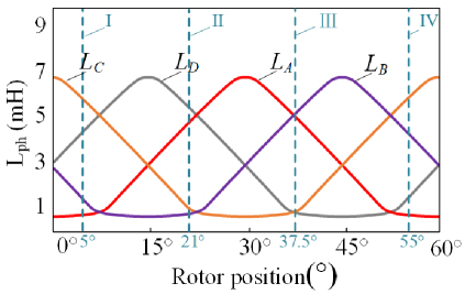
Figure 1: Typical inductance profile for a four-phase 8/6 SRM.
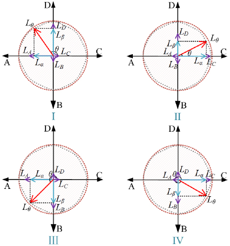
Figure 2: Inductance vector coordinate system in SRM.
According to the symmetry between each phase inductance, a rectangular coordinate can be established. To take 15∘ as an example, the relationships between the concerned four phase windings are illustrated as LALD in Fig. 2. As shown in the figure, LA, LB, LC, and LD are represented by four vectors that differ by 90∘. The modulus of each vector represents the actual corresponding phase inductance. According to the principle of vector summation, a rotating vector, which is marked as Lθ in Fig. 2, can be obtained by synthesizing all inductance vectors. The rotation trajectory of synthesized inductance vector, Lθ, is marked as a black dotted line in Fig. 2.
The relationship between synthesized inductance and four phase inductance vectors can be expressed as:
| (1) |
The x-axis inductance component, Lα, and the y-axis inductance component, Lβ, can be calculated by:
| (2) |
A standard circle trajectory, the radius of which equals to the difference between maximum phase inductance and minimum phase inductance, can be expressed as:
| (3) |
The circle trajectory is marked as a dotted orange line in Fig. 2. For steady operation, the trajectory of the synthesized inductance vector is closed to the trajectory of a standard cycle. Combing equations (1), (2), and (3), the trajectory of standard cycle and synthesized inductance vector are marked as a dotted gray line and a blue line in Fig. 3. Considering the magnetic saturation in SRM, the concerned two trajectories will not be perfectly matched but show good consistency.
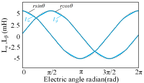
Figure 3: Schematic of the x-axis component and y-axis component of synthesized inductance vector.
Combing the geometrical relationship in Fig. 2 with equation (1), the electric angle of synthesized inductance vector, arc, can be expressed as:
| (4) |
Then, the real-time rotor position of SRM can be thus obtained by:
| (5) |
According to equations (4) and (5), the real-time rotor position of SRM can be obtained by detecting the electric angle of the synthesized inductance vector in the coordinate system.
B. Full period inductance estimation
In order to obtain inductance vectors, the inductance of each phase should be obtained for the full period. When SRM is driven by a traditional asymmetric half-bridge power converter, phase voltage can be expressed as:
Flux-linkage at moment t can be calculated by:
| (7) |
When a digital processer is employed for SRM control, the flux-linkage in the nth sampling cycle can be obtained by:
| (8) |
Since the digital processer shows high sampling frequency, rotor position can be assumed as constant between neighboring sampling cycles. Taking magnetic saturation into consideration, the inductance of each phase winding can be obtained by the digital controller as:
| (9) |
C. Rotor position estimation with asymmetry inductance
The inductance of each phase winding might be asymmetric because of machining accuracy or winding fault in the machine. In this condition, the asymmetry inductance brings large errors between estimated rotor position and actual rotor position.
Figure 4 shows the condition when the inductance of phase D is larger than the inductance of the other three phases. This might be caused by machining accuracy. In Fig. 4, ′′arc represents estimated electrical angle estimated by increased phase inductance L′′k. Accordingly, the inductance at y-axis component will be changed from a dotted line to a solid line in Fig. 4 (a).
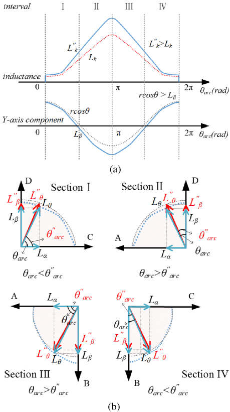
Figure 4: Inductance vector under asymmetry inductance (LDLA L LC): (a) schematic of one phase inductance increase and (b) corresponding estimated error.
Since LD is increased, we can obtain Lβ′′ Lβ in Section I and II and Lβ′′ Lβ in Section III and IV, as shown in Fig. 4 (b). Take Section I as an example. Since LD is increased, the ideal electrical angle arc and estimated electrical angle ′′arc can be expressed as:
| (10) |
It is clear that arc′′arc and the estimated electrical angle is ahead of the ideal electrical angle. Thus, an error would be obtained by equation (5) during the rotor position estimation process. A similar error can be also obtained when the inductance of phase D is smaller than the inductance of the other three phases.
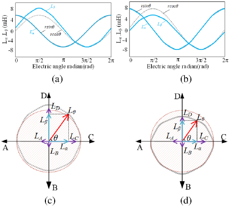
Figure 5: Trajectory of the synthetic inductance vector under nonideal phase D inductance: (a) LD is increased, (b) LD is decreased, (c) LD is increased, and (d) LD is decreased.
Figures 5 (a) and (b) show the change of Lα and Lβ when the inductance of phase D is increased and decreased, respectively. When LD is increased, the trajectory of Lβ would be changed from a dotted line to a solid line in Fig. 5 (a). When LD is decreased, the trajectory of Lβ would be changed from a dotted line to a solid line in Fig. 5 (b). Accordingly, the trajectory of the synthetic inductance vector of the two conditions can be expressed as dotted black lines in Figs. 5 (c) and (d). Obviously, the trajectory of the estimated synthetic inductance vector is deviated from the ideal trajectory, which brings significant rotor position estimation error.
For some more serious conditions, more than one phase inductance is nonideal in the machine. For example, LDLAL LC and L LCLD LA. Figure 6 shows the estimated trajectory of key parameters during the rotor position process under these two conditions. It is clear that the accuracy of rotor position estimation will be further decreased
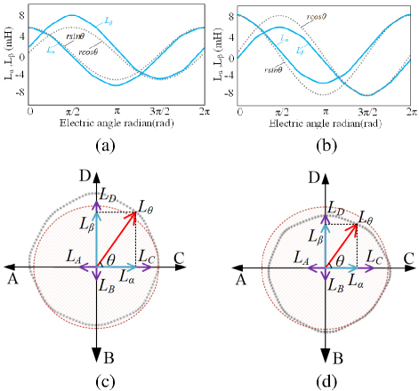
Figure 6: Trajectory of synthetic inductance vector when more than one phase inductance is nonideal: (a) LDLAL LC, (b) L LCLD LA, (c) LDLAL LC, and (d) L LCLD LA.
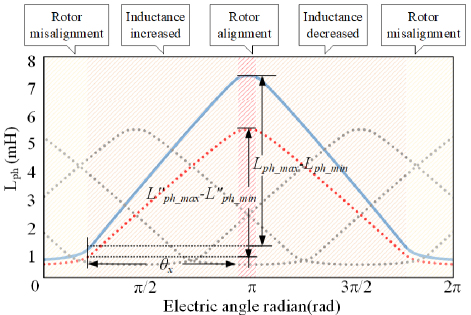
Figure 7: SRM inductor ladder.
D. Proposed rotor position estimation method with virtual inductance vector
Normally, if magnetic saturation is not considered, the trend of inductance change is approximately trapezoidal. As shown in Fig. 7, when the inductance of the motor is asymmetric, the inductance of the asymmetric phase still maintains a good trapezoidal law. The inductance of the other phases remains stable. Therefore, the symmetry between the inductances of each phase can be finally restored by analyzing and correcting the inductances of each phase separately.
According to the inductance characteristics of SRM, inductance can be divided into four intervals. As shown in Fig. 7, the inductance in the rising interval and falling interval are symmetrical to each other and have a good linear relationship with the rotor position. The inductance of the inductance minimum interval and maximum interval change less with the rotor position. In Fig. 7, assuming single-phase inductance is larger than others as an example, the solid blue line indicates the actual inductance of the deviated phase, the dashed gray line indicates the actual inductance of the non-deviated phase, and the dashed red line indicates the ideal inductance of the deviated phase. The asymmetry of inductance is mainly reflected in:
-
Rotor misalignment interval: the minimum value of inductance of each winding is different, and the minimum value of the deviation phase is larger compared to the other winding.
-
Inductance increased interval and inductance decreased interval: the rising slope and falling slope of each winding are different, and the rising slope of the deviation phase is larger than the other winding.
-
Alignment interval: the maximum inductance has a deviation and the inductance of the deviation phase is larger than other phases in the alignment interval.
To reduce the error of the estimated position restored by estimated inductance directly under conditions of inductance asymmetry, a strategy was proposed to convert the estimated inductance in this paper, the structure of which is shown in Fig. 8. The estimated inductance is converted into a virtual inductance, and then we use the virtual inductance to construct a Cartesian coordinate system to restore the rotor position. The principle of inductance conversion is as follows:
Before the inductance deviates, the inductance curve is shown as the dotted line in Fig. 7. At this time, the slope of the inductance increased interval and inductance decreased interval can be expressed as:
| (11) |
After the inductance deviation, the maximum inductance, the minimum inductance, and the slope of inductance are changed. As shown in Fig. 9, the slope of the inductance increased interval and inductance decreased interval can be expressed as:
| (12) |
where K′′nis the slope of actual inductance, Kn is the slope of ideal inductance, L′′ph_max is the maximum value of the actual inductance, L′′ph_min is the minimum value of the actual inductance, Lph_max is the maximum value of the ideal inductance, Lph_min is the minimum value of the ideal inductance, and x is the mechanical angle spanned by the rising or decreasing interval.
From the above analysis, the inductance in different intervals can be expressed as:
As shown in equation (13), it can be seen that inductance asymmetry is mainly affected by maximum inductance and the slope of the inductance. Therefore, the minimum value of the estimated inductance of each winding can be first converted by:
| (14) |
Secondly, the slope of the estimated inductance in the linear region for each winding can be converted by:
| (15) |
According to equations (14) and (15), the total expression for inductive conversion can be expressed as:
| (16) |
where L′ph_0, L′ph_1, and L′ph are inductance after step 1, inductance after step 2, and the virtual inductance converted by estimated inductance.
The block diagram of the system for the virtual inductance calculation is shown in Fig. 8. The curve of virtual inductance is shown in Fig. 9. When the coordinate system is constructed with the virtual inductance vector, the trends of the x-axis component and y-axis component of the synthesized inductance vector are shown in Fig. 10. Among them, the solid blue line indicates the component before conversion, the solid red line indicates the component after conversion, and the dashed line indicates the component of the standard circle vector at different radii. The trajectory of the virtual synthesized inductance vector is shown in Fig. 11. The dashed red line indicates the motion trajectory of the virtual synthesized inductance vector shown as L′θ, and the dashed orange line indicates the trajectory of the standard circle.
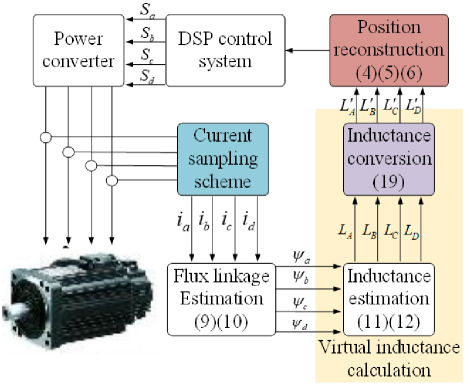
Figure 8: Block diagram of the virtual inductance calculation.
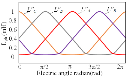
Figure 9: Virtual inductance curves under asymmetric conditions.
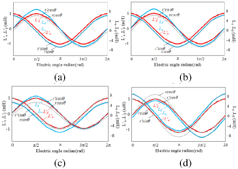
Figure 10: Trends of Lα and Lβ before and after asymmetric conversion of inductance: (a) single-phase inductance is larger, (b) single-phase inductance is smaller, (c) multi-phase inductance is larger, and (d) multi-phase inductance is smaller.

Figure 11: Vector coordinate system before and after inductance conversion.
In Fig. 9, it can be seen that the virtual inductance of each winding converted by estimated inductance has a good symmetry between the windings. The amplitude of the virtual inductance of each phase varies within 01 mH. At the same time, the virtual inductance retains the original inductance characteristics. In Figs. 10 and 11, it can be seen that the components of the virtual synthesized inductance vector have a high degree of coincidence with the components of the standard circle vector. The motion trajectory of the virtual synthesized inductor vector is coincident with the trajectory of the standard circle. At this time, the error of estimated position restoration by using the virtual synthesized inductor vector will be reduced effectively.
III. SIMULATION ANALYSIS
To verify the correctness of the theory, a simulation of four-phase 8/6 SRM was built on MATLAB/Simulink. To verify the feasibility of the method by using the inductance vector to estimate the rotor position, we simulate the process of rotor position estimation based on estimated inductance under the condition of inductance symmetry. The turn-on angle is set to 3∘, and the turn-off angle to 27∘. The small current hysteresis bandwidth is 0.51.5 A. The normal chopper current hysteresis bandwidth is 2.753.25 A. The result is shown inFig. 12.
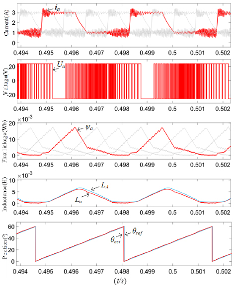
Figure 12: Schematic simulation of position reconstruction based on estimated inductance.
In Fig. 12, it can be seen that, in the normal conduction interval, normal chopping is carried out in the winding. In the non-conduction interval, small current hysteresis chopping is carried out in the winding. The current in the winding is kept continuous in the full cycle. When the switching tube is on, the voltage is positive and the magnetic linkage rises. When the switching tube is off, the voltage is reversed and the magnetic linkage decreases. The magnetic linkage of the winding can be obtained by integrating the voltage of the winding in real time. The error between the estimated inductance and the actual inductance is small. The error between the estimated rotor position and the actual rotor position is within 1∘.
To verify the effectiveness of the inductance correction strategy proposed in this paper under inductance asymmetry conditions, we simulate the position estimation process based on estimated inductance vectors and virtual inductance vectors, respectively. The simulation conditions are kept the same as above.
First, let us take the D-phase as the deviation phase to simulate the single-phase inductance asymmetry of the motor. In Fig. 13, ia, ib, ic, id are the phase currents; a, b, c, d are the magnetic linkage; LA, LB, LC, LD are the inductance of the windings; L′A, L′B, L′C, L′D are the virtual inductance of the windings; est and ref are the estimated rotor position and reference rotor position, respectively; err is the error of estimated position before inductive correction; ′err is the error of estimated position after inductive correction.
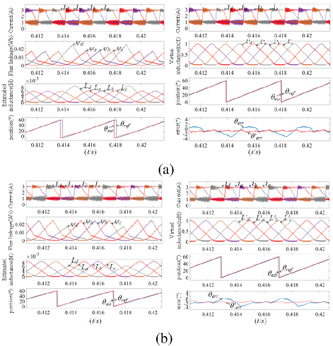
Figure 13: Schematic simulation of single-phase inductive asymmetry: (a) single-phase inductance is larger and (b) single-phase inductance is smaller.
In Fig. 13, it can be seen that under the condition of single-phase inductance asymmetry, it is still applicable to restore the rotor position by estimating inductance directly. Due to the obvious asymmetry between the estimated inductance of the deviated phase and the estimated inductance of the other phase, the error of the estimated position is increased compared with that under the condition of symmetry of inductance. As is shown in the left part of Fig. 13 (a), before correcting the inductance, the actual inductance of the deviated phase in increased interval and decreased interval is larger than its ideal inductance, which leads to the y-axis component of the synthesized inductance being smaller. Therefore, there is a significant error in the estimated position. At this time, the maximum error reaches 3∘. After correcting the inductance, as is shown in the right part of Fig. 13 (a), the virtual inductance of each phase has good symmetry. The maximum error and fluctuation are reduced. The error is within 1.5∘. Under the condition that D-phase inductance is smaller, as shown in Fig. 13 (b), the actual inductance of the deviating phases in increased interval and decreased interval are smaller than the ideal inductance, which leads to the y-axis component of the synthesized inductance vector being larger than other. Maximum error reaches 3∘, but maximum error and fluctuation are reduced after inductance correction. The error is within 1.5∘.
We then take the A and D phases as the deviation phases to simulate the multi-phase inductance asymmetry of the motor. The simulation results are shown in Fig. 14.
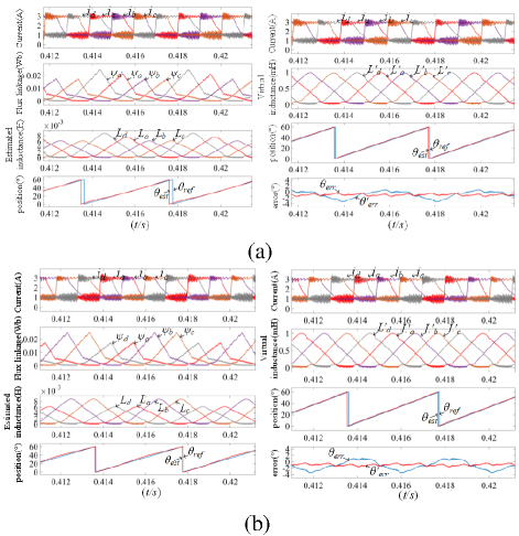
Figure 14: Schematic simulation of multi-phase inductive asymmetry condition: (a) multi-phase inductance is larger and (b) multi-phase inductance is smaller.
In Fig. 14, it is clear that under the condition of multiphase inductance asymmetry, the error of the estimated position is very obvious. As shown in Fig. 14 (a), the inductance of the A-phase and D-phase are deviated, and the deviation of the D-phase is more obvious. The results of the estimated position in different intervals all have a large error before inductance conversion. In Fig. 14 (b), the inductance of A-phase and D-phase has the same degree of deviation. The results of the estimated position in different intervals also have a large error before inductance conversion. After correcting the inductances, the maximum error and fluctuation are reduced. The error is within 1.5∘.
IV. EXPERIMENTAL ANALYSIS
In order to validate the feasibility of the strategy, some experiments were carried out on a four-phase 8/6 structure SRM. A photograph of the experimental platform is shown in Fig. 15. The parameters of the motor are listed in Table 1.
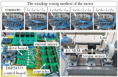
Figure 15: Experimental platform.
Table 1: Parameters of the sample machine
| Parameters | Value |
| Pitch of stator tooth (mm) | 11.6 |
| Pitch of rotor tooth (mm) | 12.8 |
| Rated voltage (V) | 24 |
| Rated power (W) | 200 |
| Rated speed (r/min) | 2000 |
| Number of stators | 8 |
| Number of rotors | 6 |
| Number of turns per pole | 35 |
First, in order to verify the validity of the sensorless position estimation strategy based on estimated inductance, an experiment was conducted under the condition of the symmetrical inductance of the four-phase windings of an 8/6 SRM. Figure 16 shows the result at 1600 r/min.
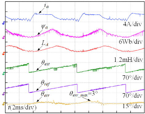
Figure 16: Position estimation based on estimated inductance.
In Fig. 16, it can be seen that the current is chopped normally in the conduction interval. A small current is injected in the non-conduction interval. The current is continuous in the full cycle. The magnetic linkage is obtained by voltage. The inductance obtained by the magnetic linkage and the current can be continuous in the full cycle, and it shows good mapping with the rotor position. Under the condition of symmetrical inductance, the rotor position can be estimated directly by estimated inductance. The error between the estimated position and the actual position is small. The error is within 2.8∘.
We can now verify the effectiveness of virtual inductance in terms of decreasing the error of estimated position in the case of inductance asymmetry. First, take the D-phase as the deviation phase and change the winding wiring (the number of turns in each pole of the D-phase is 35 turns, with the total number of turns being 70 turns, and each pole of the remaining phases of the windings is reduced to 30 turns, with the total number of turns being 60 turns). The motor speed is set to 1600 r/min, the turn-on angle is 3∘, the turn-off angle is 27∘, the small current hysteresis bandwidth is 0.51.5 A, and the normal chopper current hysteresis bandwidth is 2.753.25 A. The results are given in Fig. 17.
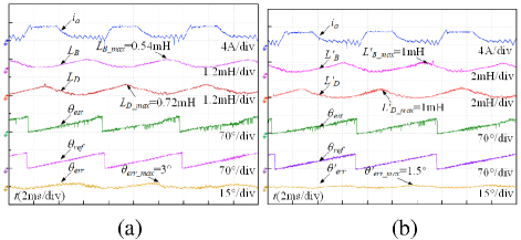
Figure 17: Position estimate experiment under the condition of single-phase inductance is larger: (a) before and (b) after.
Figure 17 (a) shows that the rotor position can be estimated directly through the estimated inductance. There is an obvious asymmetry between the inductance of the deviation phase and the inductance of the normal phase. The maximum inductance of the deviation phase is 0.72 mH, and the maximum inductance of the remaining phases is 0.54 mH. The error of estimated position increases significantly compared with that under the inductance symmetry condition. The maximum error is about 3∘. Figure 17 (b) shows that the maximum value of the virtual inductance is 1 mH, and the maximum error of the estimated position is reduced to 1.5∘ after inductance correction. Using virtual inductance vectors to reduce the error of estimated position is effective.
We then changed the winding writing so that the inductance of the D-phase is smaller than the other phases (each pole of the D-phase is 30 turns, with a total of 60 turns, and each pole of the remaining phases is 35 turns, with a total of 70 turns) and the other operating parameters remained. The results of the experiment are given in Fig. 18.
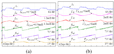
Figure 18: Position estimate experiment under the condition of single-phase inductance being smaller: (a) before and (b) after.
Figure 18 (a) shows that the maximum inductance of the deviating phase is 0.54 mH, and the maximum inductance of the remaining phases is 0.72 mH under the condition of single-phase inductance being smaller than others. The maximum error is 3∘. Figure 18 (b) shows that the maximum value of the virtual inductance of each winding is 1 mH after inductance correction. The maximum error is similarly reduced to 1.5∘.
In order to further verify the effectiveness of the strategy in the case of multiphase inductance asymmetry, the experiment was conducted under the condition of multiphase inductance asymmetry by taking A-phase and D-phase as the deviation phases and changing the winding wiring. (One of the poles of the A-phase is 35 turns, another pole is 30 turns, and the total number is 65 turns. Each pole of the D-phase is 35 turns, the total number is 70 turns. Each pole of the rest of the phase is 30 turns, the total number is 60 turns.) Other operating parameters remained the same. The results are given in Fig. 19.
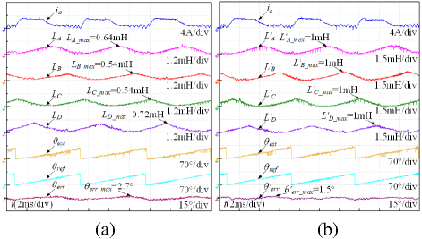
Figure 19: Position estimate experiment under the condition of multi-phase inductance being larger: (a) before and (b) after.
In Fig. 19 (a), it can be seen that the maximum inductance of the deviated A-phase and deviated D-phase is 0.64 mH and 0.72 mH, respectively, and the maximum inductance of the rest phases is 0.54 mH. The symmetry between the inductances is reduced. The maximum error of the estimated position is about 2.7∘. In Fig. 19 (b), it can be seen that the symmetry between the inductances of each phase is improved after the inductance correction, and the maximum error of the estimated position is reduced to 1.5∘.
We then changed the winding wiring so that the inductance of the A-phase and D-phase decreased at the same time (each pole of the A-phase and D-phase is 30 turns, the total number is 60 turns; each pole of the rest of the phases is 35 turns, the total number is 70 turns). Other operating parameters remained the same. The results are given in Fig. 20.
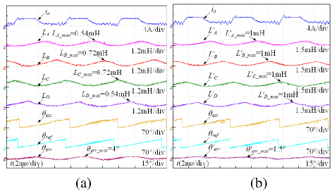
Figure 20: Position estimate experiment under the condition of multi-phase inductance being smaller: (a) before and (b) after.
In Fig. 20 (a), it can be seen that the maximum inductance of the deviated A-phase and deviated D-phase is 0.54 mH, and the maximum inductance of the remaining phases is 0.72 mH. The symmetry between the inductances of the phases is low. The maximum error between the estimated position and the actual position is about 4∘. Figure 20 (b) shows that the symmetry between the inductances of each phase is improved after the inductance correction. The maximum error of the estimated position is 1.5∘.
It can be concluded from the above experiments, under the condition of inductive asymmetry, there is an obvious difference in the inductance amplitude between the normal phase and the deviation phase. The symmetry between the phase inductances is low. After correction of the estimated inductances, the amplitude of the virtual inductance is between 0 mH and 1 mH. There is good symmetry between the virtual inductances of each phase. Under the condition of inductance asymmetry, the error of the estimated position restored by estimated inductance directly is relatively large. Maximum error and fluctuation are reduced after inductance correction. The experiments verified the effectiveness of the inductance correction strategy proposed in this paper.
V. CONCLUSION
This paper focuses on sensorless position estimation under conditions of inductance asymmetry and proposes a position estimation method based on virtual inductance vectors. The research results show that:
-
The proposed strategy is not limited by the motor structure and parameters, and can be used for SRM with other phases or parameters.
-
The proposed strategy uses the full-cycle inductance estimated in real time as an indirect basis for position estimation, which is not limited by the speed range of the motor, and it is suitable for sensorless position estimation over a wide speed range.
-
A strategy for inductance conversion under asymmetric inductance conditions is proposed in this article. The error of the estimated position is effectively reduced by using the virtual inductance to restore the rotor position under asymmetric inductance conditions.
ACKNOWLEDGEMENT
This work was supported by the Qing Lan Project (2024-2) and Jiangsu Province Universities’ Basic Science (Natural Science) Research Major Project (24KJA510001).
REFERENCES
[1] S. Ullah, S. P. McDonald, R. Martin, M. Benarous, and G. J. Atkinson, “A permanent magnet assist, segmented rotor, switched reluctance drive for fault-tolerant aerospace applications,” IEEE Trans. Ind. Appl, vol. 55, no. 1, pp. 298-305, Jan./Feb. 2019.
[2] J. Borg Bartolo, M. Degano, J. Espina, and C. Gerada, “Design and initial testing of a high-speed 45-kW switched reluctance drive for aerospace application,” IEEE Trans. Ind. Electron, vol. 64, no. 2, pp. 988-997, Feb. 2017.
[3] X. Sun, K. Diao, G. Lei, Y. Guo, and J. Zhu, “Study on segmented-rotor switched reluctance motors with different rotor pole numbers for BSG system of hybrid electric vehicles,” IEEE Trans. Veh. Technol, vol. 68, no. 6, pp. 5537-5547, June2019.
[4] W. Yan, H. Chen, S. Liao, Y. Liu, and H. Cheng, “Design of a low-ripple double-modular-stator switched reluctance machine for electric vehicle applications,” IEEE Transactions on Transportation Electrification, vol. 7, no. 3, pp. 1349-1358, Sep. 2021.
[5] C. Gan, Q. Sun, J. Wu, W. Kong, C. Shi, and Y. Hu, “MMC-based SRM drives with decentralized battery energy storage system for hybrid electric vehicles,” IEEE Trans. Power Electron., vol. 34, no. 3, pp. 2608-2621, Mar. 2019.
[6] F. Yi and W. Cai, “Modeling, control, and seamless transition of the bidirectional battery-driven switched reluctance motor/generator drive based on integrated multiport power converter for electric vehicle applications,” IEEE Trans. Power Electron., vol. 31, no. 10, pp. 7099-7111, Oct.2016.
[7] E. Bostanci, M. Moallem, A. Parsapour, and B. Fahimi, “Opportunities and challenges of switched reluctance motor drives for electric propulsion: A comparative study,” IEEE Trans. Transp. Electric., vol. 3, no. 1, pp. 58-75, Mar. 2017.
[8] N. Yan, X. Cao, and Z. Deng, “Direct torque control for switched reluctance motor to obtain high torque-ampere ratio,” IEEE Trans. Ind. Electron., vol. 66, no. 7, pp. 5144-5152, July 2019.
[9] Z. Yu, C. Gan, Y. Chen, and R. Qu, “DC-biased sinusoidal current excited switched reluctance motor drives based on flux modulation principle,” IEEE Trans. Power Electron., vol. 35, no. 10, pp. 10614-10628, Oct. 2020.
[10] D. Zhou, H. Chen, X. Wang, V. F. Pires, and J. Martins, “Synthetic sensorless control scheme for full-speed range of switched reluctance machine drives with fault-tolerant capability,” IEEE Transactions on Transportation Electrification, vol. 8, no. 4, pp. 4456-4469, Dec. 2022.
[11] A. D. Cheok and N. Ertugrul, “High robustness and reliability of fuzzy logic-based position estimation for sensorless switched reluctance motor drives,” IEEE Trans. Power Electron., vol. 15, no. 2, pp. 319-334, Mar. 2000.
[12] Y. Cai, Y. Wang, H. Xu, S. Sun, C. Wang, and L. Sun, “Research on rotor position model for switched reluctance motor using neural network,” IEEE/ASME Trans. Mechatronics, vol. 23, no. 6, pp. 2762-2773, Dec. 2018.
[13] W. Ding and K. Song, “Position sensorless control of switched reluctance motors using reference and virtual flux linkage with the one-phase current sensor in medium and high speed,” IEEE Trans. Ind. Electron., vol. 67, no. 4, pp. 2595-2606, Apr.2020.
[14] Y. Liang and H. Chen, “Circuit-based flux linkage measurement method with the automated resistance correction for SRM sensorless position control,” IET Electr. Power Appl., vol. 12, no. 9, pp. 1396-1406, Nov. 2018.
[15] C. J. Bateman, B. C. Mecrow, A. C. Clothier, P. P. Acarnley, and N. D. Tuftnell, “Sensorless operation of an ultra-high-speed switched reluctance machine,” IEEE Trans. Ind. Appl., vol. 46, no. 6, pp. 2329-2337, Nov./Dec. 2010.
[16] J. Cai, Z. Liu, and Y. Zeng, “Aligned position estimation-based fault-tolerant sensorless control strategy for SRM drives,” IEEE Trans. Power Electron., vol. 34, no. 8, pp. 7754-7762, Aug.2019.
[17] Jie Shao and Zhiquan Deng, “Sensorless control of switched reluctance motor based on current waveform detection,” Electric Power Components & Systems, vol. 49, no. 13-14, pp. 1-10,2022.
[18] T. Bamba, A. Komatsuzaki, and I. Miki, “Estimation of rotor position for switched reluctance motor at standstill,” in Proc. Power Convers. Conf., pp. 259-263, 2007.
[19] J. Kim and R. Kim, “Online sensorless position estimation for switched reluctance motors using characteristics of overlap position based on inductance profile,” IET Electr. Power Appl., vol. 13, no. 4, pp. 456-462, Apr. 2019.
[20] J. Cai and Z. Deng, “Sensorless control of switched reluctance motor based on phase inductance vectors,” IEEE Transactions on Power Electronics, vol. 27, no. 7, pp. 3410-3423, July 2012.
BIOGRAPHIES

Kai Liu received the B.S. degree in electrical engineering and automation and M.S. degree in electrical engineering from China University of Mining and Technology, in June 2011 and June 2014, respectively. From September 2014 to May 2017, Liu worked as a teaching assistant at Changzhou Vocational Institute of Mechatronic Technology, and from June 2017 to present, as lecturer and professional leader at Changzhou Vocational Institute of Mechatronic Technology. His main interests include switched reluctance machines, machine vision, robotic application.

Zongwen Jiang received the M.S degree in Nanchang University. His research focuses on motors and their control, and he currently works at Zoomlion Agriculture Machinery Co. Ltd. He is engaged in the research of electrical systems for dryers.

Qing Wang received the B.S. degree in automation from Northeastern University, Shenyang, China, in 2011, and the Ph.D. degree in electrical engineering from China University of Mining and Technology, Xuzhou, China, in 2017. In 2018, he was a Lecturer with the School of Information Engineering, Nanchang University, Nanchang, China, where he has been an Associate Professor since 2023. His research interests include electric vehicles, electrical motor drives, renewable energy generations, and micro-grids.

Jiangtao Hu received the B.S. degree in electrical engineering from Jiangxi University of Science and Technology, Ganzhou, China, in 2023. He is currently working toward the M.S. degree at the School of Information Engineering, Nanchang University, Nanchang, China. His research interests include power electronics and motor control.
ACES JOURNAL, Vol. 40, No. 9, 922–933
doi: 10.13052/2024.ACES.J.400913
© 2025 River Publishers