Influence of Pole Pitch Ratio on Performance of Segmented-stator Tubular Flux Switching Permanent Magnet Linear Generator
Rui Nie, Hao Zhang, Yifei Jia, Guozhen Zhang, Zhongwen Li, Jikai Si, and Jing Liang
School of Electrical and Information Engineering
Zhengzhou University, Zhengzhou 450001, China
nierui@zzu.edu.cn, zhanghao0405@gs.zzu.edu.cn, jiayifei2023@gs.zzu.edu.cn,
zhanggz18312@126.com, lzw@zzu.edu.cn, sijikai@zzu.edu.cn, liangjing@zzu.edu.cn
Submitted On: December 31, 2024; Accepted On: May 29, 2025
ABSTRACT
Tubular Flux-Switching Permanent Magnet Linear Generator (TFSPMLG) has high winding utilization and no radial force, which is one of the most competitive generators in direct-drive wave energy conversion system. In this paper, a Segmented-Stator TFSPMLG (SS-TFSPMLG) is proposed to solve the problems of large detent force and three-phase unbalance of TFSPMLG, and the influence of different pole pitch ratios on performance is researched for judging a proper topology for the SS-TFSPMLG. First, its topology and operation mechanism are analyzed to prove the feasibility of the generator. Second, the structural parameters of 12-slot SS-TFSPMLG with four different pole pitch ratios are calculated, and the corresponding winding arrangement is determined. The electromagnetic performances of the SS-TFSPMLG with four different pole pitch ratios are simulated and compared, including static characteristics and output characteristics. Finally, the SS-TFSPMLG topology suitable for wave power generation is determined, which lays an important foundation for the follow-up study of SS-TFSPMLG.
Index Terms: Detent force, electromagnetic design, performance analysis, pole pitch ratio, segmented-stator, tubular flux-switching permanent magnet linear generator.
I. INTRODUCTION
With the development of social economy and the aggravation of the energy crisis, the exploration and utilization of renewable energy has attracted more and more attention [1]. China has a extensive sea area and abundant marine energy. Among them, wave energy has large reserves, high energy density and good predictability, and has broad development and application prospects [2]. Compared with other forms of wave power generation systems [3, 4], the direct-drive wave power generation system has no intermediate energy conversion device, which simplifies the system structure and improves the operating efficiency. It has been widely used in the development and utilization of wave energy [5, 6]. In direct-drive wave power generation, linear generators with high power density, high operating efficiency and low detent force have always been our research goals.
Recently, the research on linear generators for the wave energy conversion system mainly focuses on permanent magnet synchronous linear generators, flux-switching permanent magnet linear generators and switched reluctance linear generators. Among them, the Flux-Switching Permanent Magnet Linear Generator (FSPMLG) with simple structure, high robustness and strong thermal stability significantly improves the reliability of the wave energy conversion system. The permanent magnet and armature coils of the FSPMLG are installed on the stator, and the mover is only composed of iron core, which avoids the irreversible demagnetization of the permanent magnet and mechanical damage. At the same time, it has high force density and efficiency [7], which combine the structural merits of a switched reluctance generator [8, 9] and the performance features of a permanent magnet synchronous linear generator. It is considered to be one of the most promising generators for wave energy conversion systems [10].
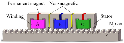
Figure 1: Configuration of the FSPMLG.
Reference [11] proposed a quadrilateral FSPMLG for wave energy collection. The generator is composed of four FSPMLGs, and its unilateral FSPMLG is shown in Fig. 1. Each phase of the stator has two U-shaped iron cores. Permanent magnets are embedded between the two U-shaped iron cores. The coils are wound in the corresponding iron core slots. The stators of each phase are separated by non-magnetic materials, and the mover is composed only of iron cores. The proposed FSPMLG has the advantages of simple structure, excellent voltage waveform, small cogging effect and high efficiency, which is suitable for the application of wave energy conversion.
To reduce the weight of the mover and broaden the application of FSPMLG, [12] proposed a split translator secondary stator FSPMLG. The stator is divided into main stator and supporting stator. The main stator is located outside the mover, which is the same as the traditional flux switching generator. The supporting stator composed of iron core is located inside the mover, which is used to improve the flux linkage of the main stator. The cogging force and force ripples are minimized by proper cascading of main and supporting stators to avoid mechanical design complexity. Benefiting from the lighter weight and higher peak speed of the mover, more power can be generated and efficiency is higher.
However, the generators in [11, 12] are all composed of a mover and a different number of single-sided stators with end windings, which increases the amount of copper used. The copper consumption of the generator reduces power generation efficiency and increases temperature rise, which has an adverse effect on the performance of the generator. Tubular linear generators of different structures are proposed in [13, 14]. The tubular structure does not have end windings, which increases the winding utilization rate and eliminates the transverse edge effect. Moreover, the tubular structure is symmetrical and does not have radial suction. By combining the advantages of a Tubular Linear generator and a Flux-Switching generator, [7, 15] proposed the Tubular Flux-Switching Permanent Magnet Linear Generator (TFSPMLG). This type of generator not only has no end windings but also has high thrust density and efficiency. Furthermore, the double convex structure has a concentrated magnetic effect which can provide higher power.
Nevertheless, this kind of cylindrical flux switching generator has the problem of high detent force caused by the end effect of the linear generator [16–18]. Excessive detent force will lead to increased vibration, noise and poor accuracy of the generator. Moreover, it can be seen from the TFSPMLG winding layout that there are side-end phases and intermediate phases in the generator winding, which leads to instability of the three-phase parameters, which in turn affects the output performance of the generator [19, 20]. Therefore, it is necessary to reduce the detent force and weaken the influence of three-phase parameter imbalance on TFSPMLG.
The relationship between different pole pitch ratios and electromagnetic performance of a high temperature superconducting flux switching linear motor is studied in [21]. By comparing the advantages and disadvantages of different pole pitch ratios, the structural parameters of the switched flux linear motor which is most suitable for urban rail transit are obtained. In this paper, the relationship between polar distance ratio and SS-TFSPMLG is also studied in order to find a more suitable structural parameter for direct-drive wave power generation.
Targeting the problems existing in the TFSPMLG, this paper innovatively proposes a SS-TFSPMLG structure. The main contents of this paper are as follows. Firstly, the basic topology and working principle of SS-TFSPMLG are described, and the winding layout design is explained in detail. Secondly, the influence of mover tooth width and end tooth width on the detent force of the generator is analyzed to determine the optimal auxiliary tooth width and mover tooth width. Finally, the static characteristics and output characteristics of four SS-TFSPMLGs with different pole pitch ratios are compared and analyzed to select different structural topologies to deal with different application scenarios.
II. THE SS-TFSPML GENERATOR
A traditional 12-slot 14-pole (12s/14p) TFSPMLG topology is shown in Fig. 2. It uses a short stator and a long mover structure. Both the permanent magnet and the armature winding are located in the stator. The permanent magnet is magnetized along the axial direction and clamped between the stator U-shaped cores. The armature winding is different from the rotating generator and the flat linear generator, and the annular structure is wound in the stator slot. In addition, the structure adds two auxiliary teeth to the stator end to weaken the influence of the end effect.
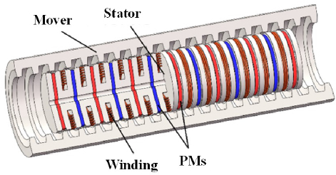
Figure 2: Configuration of the TFSPMLG.
A. Topology of the SS-TFSPMLG
To weaken the detent force and balance the inter-phase characteristics, a Segmented-Stator Tubular Flux-Switching Permanent Magnet Linear (SS-TFSPML) Generator with 12 stator slots is proposed, as shown in Fig. 3. Different from the conventional TFSPML machines, the stator of the SS-TFSPMLG is split into three segments and each segment incorporates permanent magnets (PMs), windings and stator core. There is a flux barrier between adjacent segmented-stators. Thereinto, PMs with opposite magnetization are sandwiched between dumbbell-shaped iron core, which are wound by toroidal-shaped coils. The mover consists only of iron core.
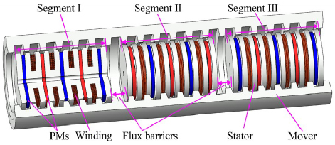
Figure 3: Configuration of the SS-TFSPMLG.
B. Design procession
The structure of 12s/14p SS-TFSPMLG in axial and radial (RZ) coordinate is shown in Fig. 4 and the dimensions are shown in Fig. 5.
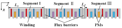
Figure 4: Structure of 12s/14p SS-TFSPMLG in RZ coordinate.
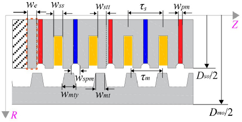
Figure 5: Dimensions of 12s/14p SS-TFSPMLG in RZ coordinate.
Evolved from TFSPMLG, SS-TFSPMLG only needs to change the stator and winding layout; electromagnetic parameters such as PM thickness and slot width are the same as TFSPMLG.
Assuming that the segments of the stator do not affect each other [22], the detent force of the whole generator is the sum of the detent forces of three segments. In order to minimize the detent force of the whole generator, the phase difference of the detent force among three segments should be 120∘. As has been shown in [23], the detent force fluctuates periodically with one pole pitch, so the distance between the segments shouldmeet
| (1) |
Ls and Lf are the axial length of the segment and the flux barrier, respectively, m is the polar distance of the mover and k is an arbitrary positive integer.
For linear generators, the pole pitch ratio of the generator has a great influence on the performance of the generator. In this paper, the SS-TFSPMLG with primary/secondary slot/pole combinations s/m of 10/12, 11/12, 13/12 and 14/12 are comparativelyanalyzed.
C. Windings configuration
Different from a permanent magnet synchronous linear generator, whose pole distance of two mover corresponds to an electric cycle, one mover pole distance of the FSPMLG corresponds to an electric cycle. According to equation (1), the phase difference of SS-TFSPMLG between the unit stators is 120∘. Therefore, the end slots of each stator segment correspond to different phases, and the six end parts belong to three-phase respectively, so that the number of coils at the end of each phase is the same and the three-phase windings are symmetrical in space. Due to the symmetry of the winding, the end effect is balanced with each other, which reduces the influence of the end effect and reduces the detent force. It is worth noting that in order to weaken the influence between the stator segments, the magnetization directions of the permanent magnets on both sides of the flux barrier are opposite, which leads to a three-phase difference. To balance the above difference, the coil winding direction of the unit stator II is opposite to that of the unit stators I and III. At this point, the topology of a three-phase SS-TFSPMLG is obtained, which effectively solves the problem of large detent force and three-phase unbalance of TFSPMLG.
Taking the 12s/14p SS-TFSPMLG shown in Fig. 4 as an example, the axial length Ls of the unit stator is 49m/9 mm. According to equation (1), the length Lf of the flux barrier is selected as 11m/9 mm (k7). Compared with TFSPMLG, since the flux barrier occupies a certain electrical angle, there is a phase difference between the coils of the unit stator. Therefore, it is necessary to redetermine the connection sequence of the winding coils in each unit stator to obtain the maximum electrical potential.
According to the calculation method of the slot pitch angle of the SS-TFSPMLG structure proposed in [24] and the calculation method of the phase difference between the unit stators in equation (2), the slot potential vector star diagrams of SS-TFSPMLG with pole pitch ratios of 10/12, 11/12, 13/12 and 14/12 are shown in Fig. 6.
is the phase difference between the unit stators.
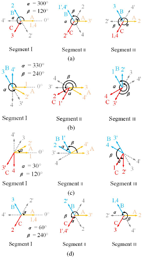
Figure 6: Star diagram of slot voltage vector of SS-TFSPMLG with pole-to-pitch ratio of (a) 10/12, (b) 11/12, (c) 13/12 and (d) 14/12.
It can be seen from the star diagrams of the slot potential vector in Fig. 6 that each phase of the four SS-TFSPMLGs with different pole pitch ratios is composed of four coils, two of which are end coils and two are internal coils. The three-phase windings are symmetrically distributed in space. In addition, it can be seen that the SS-TFSPMLG with pole pitch ratios of 10/12 and 14/12 have similar winding structures, and the SS-TFSPMLG with pole pitch ratios of 11/12 and 13/12 have similar winding structures. According to the star diagrams of the slot potential vector, the distribution factor (kd) of the winding with the pole pitch ratio of 10/12 and 14/12 is 1, and the pole pitch ratio of 11/12 and 13/12 is 0.966, as shown in Table 1.
| Pole Pitch Ratio | kd | kp | kw |
| 10/12 | 1 | 1 | 1 |
| 11/12 | 0.966 | 1 | 0.966 |
| 13/12 | 0.966 | 1 | 0.966 |
| 14/12 | 1 | 1 | 1 |
Different from a flat-type linear machine or rotary machine, the coils of the TFSPML machine are circular and the coils in a single slot can form an effective conductor. In that case, the coil pitch factor (kp) is equal to one. Hence, the winding factor (kw) is determined by the distribution factor. The winding factor of four SS-TFSPMLGs are listed in Table 1.
III. EFFECT OF MOVER TOOTH WIDTH AND END TOOTH WIDTH
As can be concluded from equation (3), the detent force of the SS-TFSPMLG is composed of the third and its multiple harmonic components of the detent force in each segment. Thus, the third and its multiple harmonics components of the detent force in each segment should be as small as possible:
| (3) |
Fdn is the n-th harmonic amplitude of the unit detent force, dn is the n-th harmonic phase of the unit detent force and fw is the detent force of the whole generator.
According to [21], the end tooth width wet and mover tooth width wmt have a great influence on the detent force. Figure 7 shows the no-load EMF, THD and detent force of SS-TFSPMLG with a pole pitch ratio of 10/12 versus different wet and wmt values. It can be observed that wet and wmt have a higher sensitivity on the THD and the detent force than on the no-load EMF. Therefore, the influence of wet and wmt on the THD and detent force should be given priority. From Fig. 7 (a), the no-load EMF is increased with the increment of wet and wmt. The lower value of THD is the interval between 3.5 mm and 5.5 mm for wet with wmt 6 mm, where THD is less than 5%, as shown in Fig. 7 (b). Also, the region with the lower value of detent force is in the range of 6 mm to 6.3 mm of wmt and 3.5 mm to 4 mm or 9.5 mm to 10 mm of wet, as shown in Fig. 7 (c). Consequently, considering the higher no-load EMF, lower THD and lower detent force, wmt and wet are optimized as 6 mm and 4 mm, respectively. Likewise, for SS-TFSPMLG with pole pitch ratio of 11/12, 13/12 and 14/12, the above method is applied to determine their wet values of 9.5 mm, 6 mm and 5 mm, and wmt values of 6.3 mm, 6 mm and 8 mm, respectively. The major parameters of the SS-TFSPMLG are listed in Table 2.
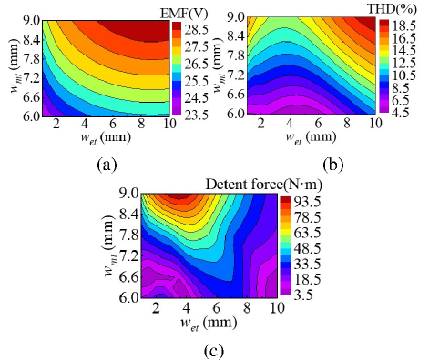
Figure 7: Output characteristics of SS-TFSPMLG versus mover tooth width and end tooth width: (a) no-load back electromotive force (EMF), (b) total harmonic distortion (THD), and (c) detent force.
Table 2: Parameter of the SS-TFSPMLG
| Item | 12-Stator-Slot | |||
| Pole pitch ratio | 10/12 | 11/12 | 13/12 | 14/12 |
| Outer diameter of mover Dmo | 118 mm | |||
| Outer diameter of stator Dso | 73 mm | |||
| Diameter of stator yoke Dy | 25 mm | |||
| Stator pole pitch s | 24 mm | |||
| Number of slots Ns | 12 | |||
| Stator tooth tip width wstt | 6 mm | |||
| Stator slot width wss | 6 mm | |||
| PM width wpm | 4 mm | |||
| PM notch width wpmn | 6 mm | |||
| Mover tooth width wmt | 6 mm | 6.3 mm | 6 mm | 8.4 mm |
| Mover teeth yoke width wmty | 9 mm | |||
| End tooth width wet | 4 mm | 9.5 mm | 6 mm | 5 mm |
| Flux barrier length Lfb | 109/72 m |
301/288 m |
19/16 m |
11/9m |
| Number of turns per coil Nc | 60 | |||
| Velocity of mover v | 1 m/s |
IV. PERFORMANCE EVALUATION
In this section, the electromagnetic performances of the four optimized SS-TFSPMLGs are predicted by finite-element, including static characteristics and output characteristics.
A. Static characteristics analysis
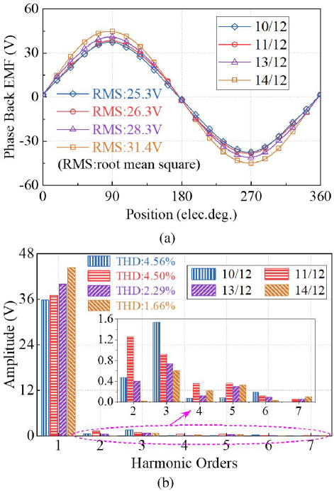
Figure 8: Back EMFs of 12-slot SS-TFSPMLGs @ v 1 m/s. (a) Waveforms of phase back EMF and (b) harmonic spectrum of phase back EMF.
Figure 8 shows the open-circuit back-EMF E0 of 12-slot SS-TFSPMLG with different pole pitch ratios at a rated speed of 1 m/s. It can be seen that the generators with pole pitch ratios of 13/12 and 14/12 show higher back EMF than the generators with pole pitch ratios of 10/12 and 11/12, which is attributed to the higher number of mover poles. The larger the pole pitch ratio, the higher the effective magnetic flux and the higher the utilization rate of magnetic flux, thereby increasing the back EMF. The back-EMF fundamental components of SS-TFSPMLG with pole pitch ratios of 10/12, 11/12, 13/12 and 14/12 are 25.3, 26.3, 28.3 and 31.4 V, respectively, with the corresponding THD value of 4.56, 4.50, 2.29 and 1.66%. The THD value will decrease with the increase of the pole pitch ratio. This is because the larger the pole pitch ratio, the closer the distribution of the air gap magnetic field will be to the ideal sinusoidal waveform, and the lower the harmonics. Therefore, the generator with a pole pitch ratio of 14/12 can provide the highest back EMF and the lowest THD.
The detent force and electromagnetic force of the 12-slot SS-TFSPMLG are shown in Fig. 9. Since there exists a magnetic coupling effect between segmented-stators, the detent force shown in Fig. 9 (a) is higher than the theoretical value in section III. The detent forces of the SS-TFSPMLG with pole pitch ratios of 11/12 and 14/12 are smaller than that of the other two counterparts.
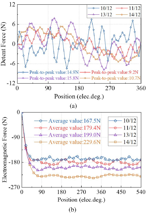
Figure 9: Force characteristics of 12-slot SS-TFSPMLGs. (a) Detent force and (b) electromagnetic force @v 1 m/s and R 10 .
The average values of the electromagnetic force for four SS-TFSPMLGs under the v 1 m/s and R 10 condition are 167.5, 179.4, 199.0 and 229.6 N, respectively, as shown in Fig. 9 (b). The electromagnetic force of the generator with a pole pitch ratio of 14/12 is the largest, owing to a higher fundamental component of back EMF. Meanwhile, due to the lowest THD and lower detent force, its peak-to-peak force ripple is the lowest, with a value of 13.3 N. In addition, the force ripple ratios of four SS-TFSPMLGs, which is the ratio of the peak-to-peak value to the average value of electromagnetic force, are acceptable at 10.09, 12.57, 8.29 and 5.78%, respectively. Hence, from the viewpoint of the detent force and electromagnetic force, the SS-TFSPMLG with a pole pitch ratio of 14/12 exhibits the highest average value and the lowest force ripple ratio.
B. Output characteristic analysis
For a generator applied to wave energy conversion, the output characteristics, including output voltage, voltage regulation, output power, electromagnetic force and efficiency, are key indices. Hence, to evaluate generation performance comprehensively, the output characteristics operating within a load range and a mover speed range are analyzed by finite-element analysis (FEA).
Firstly, the output characteristics operating with different resistive loads are concerned with a speed of 1 m/s. Figure 10 (a) shows the output voltage of the 12-slot SS-TFSPMLG versus different armature currents. It can be seen that when the armature current is less than about 5A, the output voltage of the generator with a pole pitch ratio of 14/12 is greater than that of the other counterparts, whereas that of the generator with a pole pitch ratio of 11/12 is the largest with armature current increment beyond 5 A. On the rated generation condition (RN 10), the output voltage of the proposed SS-TFSPMLG with a pole pitch ratio of 14/12 is 27.1 V, which is about 17.01, 13.15 and 7.54% higher than that of the counterparts with pole pitch ratios of 10/12, 11/12 and 13/12, respectively. Moreover, the output voltage curves of the generators with pole pitch ratios of 10/12 and 11/12 are smoother than that of the counterparts with pole pitch ratios of 13/12 and 14/12, which can reflect the degree of deviation of output voltage from the back-EMF, i.e., voltage regulation. The voltage regulation of the generator can be expressed as
| (4) |
where E0, U and UN denote the back-EMF, output voltage and rated voltage, respectively.
As shown in Fig. 10 (b), the voltage regulation also indicates the lower voltage regulation in the generators with pole pitch ratios of 10/12 and 11/12, compared with the other two SS-TFSPML generators. This is due to the smaller pole pitch ratio. The larger the pole pitch ratio, the higher the back EMF, and the greater the influence of armature reaction, magnetic flux leakage and magnetic field saturation effect when the load is loaded, resulting in a decrease in the output voltage and an increase in the voltage regulation. Therefore, generators with pole pitch ratios of 10/12 and 11/12 have lower voltage regulation.
For SS-TFSPMLG, the three-phase voltages are completely symmetrical, owing to the scheme of the segmented-stators leading to the spatially symmetrical winding. Therefore, the output power can be calculated by
| (5) |
where I is the rms value of armature current.
According to equation (5), Fig. 11 shows the output power of the four generators varying with the armature current for the resistive loads, where the output power values are 160.9, 172.1, 190.7 and 220.0 W working at rated generation condition, respectively. Meanwhile, since the output power is proportional to the output voltage, its variation trends are similar to that in Fig. 10 (a). Therefore, the generator with a pole pitch ratio of 11/12 can provide better overload capability. For the armature current less than about 5 A operation condition, the output power of the SS-TFSPMLG with a pole pitch ratio of 14/12 is the largest among the four generators, albeit with the highest voltage regulation.
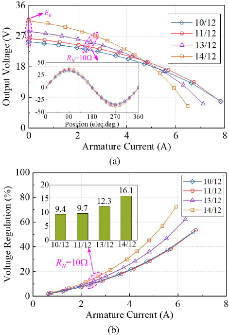
Figure 10: Output voltage and voltage regulation of 12-slot SS-TFSPMLG versus armature currents @ 1 m/s. (a) Output voltage and (b) voltage regulation.
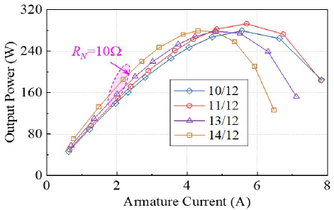
Figure 11: Output power of 12-slot SS-TFSPMLG versus armature currents @ 1 m/s.
The discrepancies in the output characteristics with different armature currents are mainly caused by the winding reactance difference. For the proposed SS-TFSPMLG, similar to the FSPML machine, the d-axis inductance is nearly the q-axis inductance as shown in Table 3, though it has the segmental stator structure. Thus, the simplified phasor diagram neglecting winding resistance of the proposed generator work with resistive load is shown in Fig. 12, where xs is synchronous reactance, and 1 and 2 are the internal power factor angles that armature current I and output voltage U lag behind back-EMF E0. The synchronous reactance can be expressed by the d/q axis reactance, approximately. In that case, suppose that the back-EMF remains constant, for the generator with large reactance, the reactance voltage drops increase with the increase of armature current, which greatly reduces the output voltage, resulting in an increase in voltage regulation. Meanwhile, the larger internal power factor angle also increases, which results in the q-axis current easily getting the peak value and then decreasing. Hence, it is easier for the output power to reach saturation and then decline rapidly with the increase of the armature current. The corresponding overload capacity of the generator is also weak.
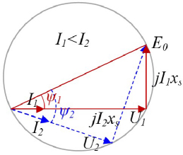
Figure 12: Simplified phasor diagram of the proposed generator with resistive load.
From Table 3, it can be seen that the reactance of the generator with a pole pitch ratio of 14/12 is the largest, followed by the generator with a pole pitch ratio of 13/12, and that of the generators with pole pitch ratios of 11/12 and 10/12 are close. Therefore, the voltage regulations of the generators with pole pitch ratios of 11/12 and 10/12 are lower than generators with pole pitch ratios of 13/12 and 14/12, which is consistent with Fig. 10 (b). Moreover, compared with the generator with a pole pitch ratio of 10/12, the counterpart with a pole pitch ratio of 11/12 has better overload capability because of higher voltage.
Table 3: Output characteristics of the SS-TFSPMLG with 10 at 1 m/s
| Parameter | 10/12 | 11/12 | 13/12 | 14/12 |
| Phase EMF (rms) (V) | 25.3 | 26.3 | 28.3 | 31.4 |
| Output voltage (rms) (V) | 23.2 | 24.0 | 25.2 | 27.1 |
| Output current (A) | 2.3 | 2.4 | 2.5 | 2.7 |
| Voltage regulation (%) | 9.4 | 9.7 | 12.3 | 16.1 |
| THD of the phase EMF (%) | 4.56 | 4.50 | 2.29 | 1.66 |
| Output power (W) | 160.9 | 172.1 | 190.7 | 220.0 |
| Electromagnetic force (N) | 167.5 | 179.4 | 190.7 | 229.6 |
| Force ripple (%) | 10.09 | 12.57 | 8.29 | 5.78 |
| Efficiency (%) | 92.7 | 92.3 | 92.4 | 92.8 |
| d-axis inductance (mH) | 11.4 | 10.7 | 11.9 | 13.6 |
| q-axis inductance (mH) | 12.0 | 11.5 | 12.4 | 15.0 |
| d-axis reactance () | 2.49 | 2.57 | 3.37 | 4.15 |
| q-axis reactance () | 2.62 | 2.76 | 3.51 | 4.58 |
The losses and efficiency of the four generators are shown in Fig. 13. Ignoring mechanical loss, the total loss is composed of the copper loss and iron loss, which can be respectively calculated by
| (6) | ||
| (7) |
where PCu and PFe are copper and iron losses, respectively; Bn is the nth harmonic of the magnetic flux density, N is the number of harmonics, f is the frequency, and kh and ke are loss coefficients associated with the iron core. Therefore, the efficiency can be calculated as
| (8) |
It is worth noting in Fig. 13 (a) that due to the same winding resistance, the copper losses of the four generators are the same under the same armature current, thus only represented by one blue dotted line. In addition, it can be seen from Fig. 13 (a) that the iron loss of the four generators increases slightly with the increase of the pole pitch ratio. This is because the magnetic flux density of the generator increases with the increase of the pole pitch ratio, and the iron loss is also larger. However, the operating frequency, core material and core thickness of the four generators are the same, so the iron consumption generally changes little and is almost the same. Thus, the total loss waveforms of the four generators are almost overlapped. From Fig. 13 (b), the four generators have a wide range of high-efficiency operating loads regions. Moreover, the SS-TFSPMLGs with pole pitch ratios of 14/12 and 11/12 have the highest efficiency owing to higher output power when the armature current is relatively small and large, respectively.
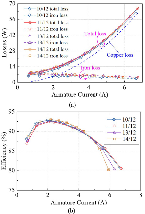
Figure 13: (a) Losses and (b) efficiency of 12-slot SS-TFSPMLGs versus armature currents @ 1 m/s.

Figure 14: Output voltage of 12-slot SS-TFSPMLGs versus speeds @ RN 10 .
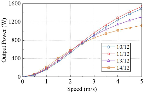
Figure 15: Output power of 12-slot SS-TFSPMLGs versus speeds @ RN 10 .
Based on the above analysis, it can be found that the SS-TFSPMLG with a pole pitch ratio of 11/12 has superiority in the higher current generation condition, while the generator with a pole pitch ratio of 14/12 is preferential for the lower current application. The analysis results working at the rated condition are summarized in Table 3.
On the other hand, the output characteristics of four generators operating at different speeds are analyzed, with a resistive load of 10. Figure 14 shows the variation of the output voltage with the change in speed. It can be observed that the output voltages of four generators increase with the speed increment. When the speed of the mover is the rated speed, the SS-TFSPMLG with the pole pitch ratio of 14/12 has a higher output voltage. Considering that the inductance of the generator with the pole pitch ratio of 14/12 is the largest, the inner power factor angle increases faster and the output voltage increases slower as the speed grows. Therefore, when the speed exceeds about 2.5 m/s, the generator with the pole pitch ratio of 11/12 has the highest output voltage. It can be seen from Fig. 15 that the variation of output power is the same as that of output voltage. According to the efficiency curve in Fig. 16, it can be concluded that, near the rated speed, the efficiency of SS-TFSPMLG with the pole pitch ratio of 14/12 is slightly higher than that of the other three, and the four generators can maintain high efficiency operation in this speed range. In summary, same as the variable load output characteristics, at the rated speed and its vicinity, the generator with the pole pitch ratio of 14/12 has more advantages, while the generator with the pole pitch ratio of 11/12 has the best overspeed ability. Therefore, the SS-TFSPMLG with the pole pitch ratio of 14/12 is more suitable for low-speed direct-drive wave energy conversion systems.
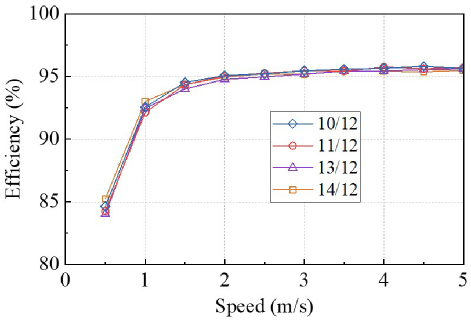
Figure 16: Efficiency of 12-slot SS-TFSPMLGs versus speeds @ RN 10 .
V. CONCLUSION
In this paper, a Segmented-Stator TFSPMLG (SS-TFSPMLG) topology is proposed innovatively. The problem of large detent force and three-phase imbalance is solved theoretically through the structural design and winding arrangement of the new topology. Furthermore, through the further optimization design of the mover tooth width and the end tooth width, the detent force is further reduced. Finally, the electromagnetic characteristics of 12-slot SS-TFSPMLG with four different pole pitch ratios are compared and analyzed, and the application conditions of the generator under different pole pitch ratios are clarified. The results show that the SS-TFSPMLG with a polar pitch ratio of 14/12 has the best output voltage, output power and efficiency at and near the rated point, which is suitable for low-speed direct-drive wave power generation. The generator with a pole pitch ratio of 11/12 has the best overload and overspeed performance, which is suitable for large power and speed power generation occasions.
ACKNOWLEDGMENT
This work was sponsored by the National Natural Science Foundation of China (Grant No. 52207067), the Natural Science Foundation of Henan (Grant No. 252300421095), the National Natural Science Foundation of China (Grant No. 52277069, 52307070), the Major Special Project for Collaborative Innovation in Zhengzhou (Grant No. 20XTZX12023) and by the China Postdoctoral Science Foundation (Grant No. 2023M743155).
REFERENCES
[1] Y. Zhang, Z. Lin, and Q. Liu, “Marine renewable energy in China: Current status and perspectives,” Water Science and Engineering, vol. 7, no. 3, pp. 285-305, Oct. 2014.
[2] L. Li, X. Zhang, Z. Yuan, and Y. Gao, “Multi-stable mechanism of an oscillating-body wave energy converter,” IEEE Trans. Sustain. Energy, vol. 11, no. 1, pp. 500-508, Jan. 2020.
[3] M. Noman, G. Li, M. W. Khan, K. Wang, and B. Han, “A multi-stage design approach for optimizing a PMSG-based grid-connected ocean wave energy conversion system,” Prot. Control Mod. Power Syst., vol. 9, no. 6, pp. 122-142, Nov. 2024.
[4] M. Alberdi, M. Amundarain, A. J. Garrido, I. Garrido, O. Casquero, and M. De la Sen, “Complementary control of oscillating water column-based wave energy conversion plants to improve the instantaneous power output,” IEEE Trans. Energy Convers., vol. 26, no. 4, pp. 1021-1032, Dec. 2011.
[5] L. Zhao and Q. Lu, “A novel tubular partitioned stator flux-reversal permanent magnet linear machine for direct-drive wave energy generation,” IEEE Trans. Magn., vol. 55, no. 11, pp. 1-7, Nov. 2019.
[6] F. Mwasilu and J. W. Jung, “Potential for power generation from ocean wave renewable energy source: A comprehensive review on state-of-the-art technology and future prospects,” IET Renew. Power Gener., vol. 13, no. 3, pp. 363-375, Feb. 2019.
[7] G. Zhang, R. Nie, J. Si, X. Feng, and C. Wang, “Analysis of the operation principle for tubular flux-switching permanent magnet linear machine,” COMPEL Int. J. Comp. Math. Electr. Electron. Eng., vol. 42, no. 2, pp. 285-301, Jan. 2023.
[8] M. M. Nezamabadi, E. Afjei, and H. Torkaman, “Design and electromagnetic analysis of a new rotary-linear switched reluctance motor in static mode,” Applied Computational Electromagnetics Society (ACES) Journal, vol. 31, no. 2, pp. 171-179, Feb. 2016.
[9] I. Mahmoud, M. Fathallah, and H. Rehaoulia, “Nonlinear modelling approach for linear switched reluctance motor and its validation by two dimensional FEA,” Applied Computational Electromagnetics Society (ACES) Journal, vol. 31, no. 2, pp.195-203, Feb. 2016.
[10] J. Faiz and A. Nematsaberi, “Linear electrical generator topologies for direct-drive marine wave energy conversion: An overview,” IET Renew. Power Gener., vol. 11, no. 9, pp. 1163-1176, July 2017.
[11] L. Huang, H. Yu, M. Hu, J. Zhao, and Z. Cheng, “A novel flux-switching permanent-magnet linear generator for wave energy extraction application,” IEEE Trans. Magn., vol. 47, no. 5, pp. 1034-1037, May 2011.
[12] O. Farrok, M. R. Islam, M. R. I. Sheikh, Y. Guo, and J. G. Zhu, “A split translator secondary stator permanent magnet linear generator for oceanic wave energy conversion,” IEEE Trans. Ind. Electron., vol. 65, no. 9, pp. 7600-7608, Sep. 2018.
[13] L. Huang, H. Yu, M. Hu, C. Liu, and B. Yuan, “Research on a tubular primary permanent-magnet linear generator for wave energy conversions,” IEEE Trans. Magn., vol. 49, no. 5, pp. 1917-1920, May 2013.
[14] S. L. Ho, Q. Wang, S. Niu, and W. N. Fu, “A novel magnetic-geared tubular linear machine with Halbach permanent-magnet arrays for tidal energy conversion,” IEEE Trans. Magn., vol. 51, no. 11, pp. 1-4, Nov. 2015.
[15] L. Huang, J. Liu, H. Yu, R. Qu, H. Chen, and H. Fang, “Winding configuration and performance investigations of a tubular superconducting flux-switching linear generator,” IEEE Trans. Appl. Supercond., vol. 25, no. 3, pp. 1-5, June 2015.
[16] S. Chi, J. Yan, L. Shan, and P. Wang, “Detent force minimizing for moving-magnet-type linear synchronous motor,” IEEE Trans. Magn., vol. 55, no. 6, pp. 1-5, June 2019.
[17] Y.-W. Zhu, D.-H. Koo, and Y.-H. Cho, “Detent force minimization of permanent magnet linear synchronous motor by means of two different methods,” IEEE Trans. Magn., vol. 44, no. 11, pp. 4345-4348, Nov. 2008.
[18] X. Chai, J. Si, Y. Hu, Y. Li, and D. Wang, “Characteristics analysis of double-sided permanent magnet linear synchronous motor with three-phase toroidal windings,” Applied Computational Electromagnetics Society (ACES) Journal, vol. 36, no. 8, pp. 1099-1107, Aug. 2021.
[19] X. Z. Huang, J. Li, Q. Tan, Z. Y. Qian, C. Zhang, and L. Li, “Sectional combinations of the modular tubular permanent magnet linear motor and the optimization design,” IEEE Trans. Ind. Electron., vol. 65, no. 12, pp. 9658-9667, Dec. 2018.
[20] Q. Tan, M. Wang, L. Li, and J. Li, “Research on noninteger pole number for segmental permanent magnet linear synchronous motor,” IEEE Trans. Ind. Electron., vol. 68, no. 5, pp. 4120-4130, May 2021.
[21] R. Cao, M. Cheng, C. C. Mi, and W. Hua, “Influence of leading design parameters on the force performance of a complementary and modular linear flux-switching permanent-magnet motor,” IEEE Trans. Ind. Electron., vol. 61, no. 5, pp. 2165-2175, May 2014.
[22] K. Kim, M. Hwang, H. K. D. Kim, and H. Cha, “Torque improvement and magnetic flux leakage reduction in interior permanent magnet axial flux motors with flux barrier structure,” IEEE Access, vol. 12, pp. 150869-150879, Oct. 2024.
[23] J. Zhao, Q. Mou, K. Guo, X. Liu, J. Li, and Y. Guo, “Reduction of the detent force in a flux-switching permanent magnet linear motor,” Trans. Energy Convers., vol. 34, no. 3, pp. 1695-1705, Sep.2019.
[24] G. Zhang, R. Nie, J.-K. Si, X. Feng, and C. Wang, “Sectional modular technology for reducing detent force of linear unit in linear-rotary flux-switching permanent-magnet generator for wind-wave combined energy conversion,” Applied Computational Electromagnetics Society (ACES) Journal, vol. 38, no. 4, pp. 286-296, Apr. 2023.
BIOGRAPHIES

Rui Nie received a B.S. degree in electrical engineering from Henan Polytechnic University, Jiaozuo, China, in 2015, and a Ph.D. degree in electrical engineering from the China University of Mining and Technology, Xuzhou, China, in 2020. She is currently an assistant research fellow at Zhengzhou University. Her current research interests include two-degree-of-freedom machines, linear motor design and control, and renewable energy generation technology.

Hao Zhang was born in Henan, China, in 2001. He received the B.S. degree in electrical engineering and automation from China University of Petroleum, Qingdao, China, in 2023. He is currently working toward the M.S. degree in School of Electrical Engineering of Zhengzhou University, Zhengzhou, Henan. His research interests include renewable energy generation technology, and two-degree-of-freedom motor control.

Yifei Jia was born in Henan, China, in 1999. She received the B.S. degree in electrical engineering and automation from Shanghai University of Electric Power, Shanghai, China, in 2021. She is currently working toward the M.S. degree in School of Electrical Engineering of Zhengzhou University, Zhengzhou, Henan. Her research interests include linear rotary generator design and optimization, and renewable energy generation technology.

Guozhen Zhang was born in Anhui Province, China, in 1996. He received the B.S. degree in Electrical Engineering from Henan University of Technology in 2020, and the M.S. degree in Electrical Engineering with the School of Electrical and Information Engineering, Zhengzhou University, Zhengzhou, China. His research interests include the design and optimization of two-degree-of-freedom machines and linear machines.

Zhongwen Li received the B.S. degree from Zhengzhou University, Zhengzhou, China, in 2011, and the Ph.D. degree from the Shenyang Institute of Automation, Chinese Academy of Sciences, Shenyang, China, in 2017. He is currently an Associate Professor with the School of Electrical Engineering, Zhengzhou University. His main research interests include distributed control and multi-agent system.

Jikai Si received a B.S. degree in electrical engineering and automation from the Jiaozuo Institute of Technology, Jiaozuo, China, in 1998; the M.S. degree from Henan Polytechnic University, Jiaozuo, China, in 2005; and the Ph.D. degree in 2008 from the China University of Mining and Technology, Xuzhou, China. He is currently a distinguished professor at Zhengzhou University. His main research interests include the theory and control of special motors.

Jing Liang received a B.E. degree from Harbin Institute of Technology, Harbin, China, in 2003, and a Ph.D. degree from Nanyang Technological University, Singapore, in 2009. She is currently a Professor at the School of Electrical and Information Engineering, Zhengzhou University, Zhengzhou, China. Her main research interests are evolutionary computation, swarm intelligence, multi-objective optimization, and neural network. She currently serves as an Associate Editor for IEEE Transactions on Evolutionary Computation and Swarm and Evolutionary Computation.
ACES JOURNAL, Vol. 40, No. 9, 934–944
doi: 10.13052/2024.ACES.J.400914
© 2025 River Publishers