Design and Optimization of Hybrid Excitation Switched Reluctance Motors for Electric Transportation Vehicles
Qing Wang, Jiangtao Hu, Jiaxin Ding, Fengshuo Liu, Yumeng Zhu, and Yongqing Deng
Department of Electrical Engineering
Nanchang University, Nanchang 330031, China
wangq@ncu.edu.cn, 3363830583@qq.com, 1061626288@qq.com, 13767736595@163.com,
1091306318@qq.com, dengyq@ncu.edu.cn
Submitted On: December 31, 2024; Accepted On: May 29, 2025
ABSTRACT
To improve the torque characteristic of hybrid excitation switched reluctance motors (HESRM), the structure and excitation current of HESRM are comprehensively studied. First, a novel structure is introduced to HESRM, in which pole pieces are added to the rotor salient pole to reduce output torque ripple. The effect of different structural parameters in HESRM is studied by finite element model (FEM). To evaluate the torque characteristic of the machine, mean torque and torque are chosen as key evaluation factors of HESRM. To achieve a quick and accurate optimization process, an artificial neural network (ANN) based prediction model is built according to FEM results, in which system structure is employed as input components and evaluate factors are employed as output components. Then, genetic algorithm (GA) is designed for HESRM structure optimization. With improved GA and ANN prediction models, the torque performance of HESRM can be further improved. Finally, experimental and simulation results are given to validate the accuracy of machine design.
Index Terms: Finite element analysis (FEA), genetic algorithm, hybrid excitation switched reluctance motor (HESRM), multi-objective optimization, neural network, torque performance.
I. INTRODUCTION
Compared with permanent magnet (PM) motors and synchronous motors, switched reluctance motors (SRMs) show advantages in merits such as simple structure, high fault tolerance, and wide speed range, and can be widely used in many industrial and commercial areas [1–5]. However, due to its double salient structure, SRM suffers from torque ripple and a relatively low space utility rate [6]. Thus, many scholars focus on improving the torque performance and prolonging the efficient use area of SRM.
Hybrid excitation switched reluctance motor (HESRM) is a type of double salient pole motor, whose structure is similar to traditional switched reluctance motor (TSRM). Unlike TSRM, phase windings of HESRM are excited by a sinusoidal alternating current with DC bias (i.e., phase current consists of both DC and AC components) [7]. HESRM inherits the advantages of the simple and reliable structure from TSRM and overcomes the defect of the low volume utilization rate in TSRM. In [8], the effect of distributed and centralized armature winding schemes is comprehensively studied and compared. Traditionally three-phase power inverters can be employed for HESRM control, by which the drive system achieves high power density and wide operating range. In [9], a four-phase DC-assisted bipolar switched reluctance motor is designed and optimized, by which torque ripple can be effectively reduced. By recombining DC-assisted windings and AC excitation windings introduced in [9], a sinusoidal AC with DC bias can be applied to phase windings of TSRM to improve the torque performance [10].
To reduce the torque ripple of HESRM, scholars have mainly studied two aspects: machine design and optimization [11] and control strategy design for a given motor [12]. Since the double salient structure shows high nonlinearity, it is hard to build a mathematic model for performance analysis, and finite element analysis (FEM) is thus required for most cases. In [13], stator pole arcs are optimized by FEA and the motor has more flexible pole pairs under “bipolar sine and DC bias” excitation mode. Moreover, to improve the torque performance, both mean torque and torque ripple should be considered simultaneously. Thus, multi-objective evaluations should be taken during the optimization process [14], which makes the optimization process more complex. The most commonly used optimization process has the following steps [15]: (a) Discrete torque data should be obtained by FEA; (b) According to FEA results, a fitting model should be realized on time-domain simulation platform to achieve multi-objective evaluation results; (c) According to multi-objective optimization results, the machine structure will be optimized time by time to achieve the desired indicators. This optimization process is complicated and costs time.
To overcome the above issues, a HESRM is designed and optimized in this paper. The proposed HESRM is generated from 8/6 TSRM, and the structure is optimized to reduce torque ripple. A FEM is built to analyze the effects of structure parameters and excitation current on the torque performance of the machine. To achieve fast multi-objective optimization, a neural network is employed to establish a torque performance prediction model. To conclude, simulation and experimental results are given to verify the proposed machine structure and optimization process.
II. OPERATING PRINCIPLES OF HESRM
Figure 1 shows the topology of 8/6 HESRM. The stator and rotor present a double salient structure, phase windings are concentrated on each stator tooth, and windings on every two opposing stator teeth are connected in series. Key parameters of the HESRM are given in Table 1.
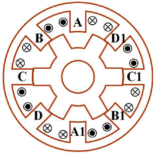
Figure 1: Four-phase 8/6 HESRM.
Table 1: Key parameters of 8/6 HESRM
| Phase windings | 1.5 mm2 copper |
| Turns of windings | 60 |
| Air gap | 0.4 mm |
| Axial length | 76.5 mm |
| Stator pole arc | 20∘ |
| Rotor pole arc | 22∘ |
| Rated power | 200 W |
| Rated voltage | 24 V |
| Rated speed | 500 r/min |
HESRM is excited by AC current with DC bias. The block diagram of the current control strategy is shown in Fig. 2. Main circuit topology is shown in Fig. 3. The absolute value of the reference current is determined by the speed controller. When the speed is lower than the reference speed, the absolute value of the reference current increases, generating a larger torque to increase the speed. When the speed is higher than the reference speed, the situation is the opposite. The d-axis reference current is set to 0, i0/is. The phase of the reference value of the four-phase winding current is determined by the rotor position, and the amplitude is determined by the q-axis reference current. The transient current of each phase can be expressed by
| (1) |
i0 is the DC bias of the sinusoidal current, is is the amplitude of the AC component, e is the angular velocity of the AC component, and k (ka, b, c or d) is the phase angle.
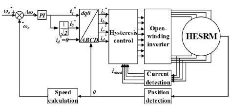
Figure 2: Current control block diagram.
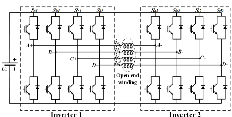
Figure 3: Topology of the main circuit.
Neglecting magnetic saturation, phase inductance of HESRM can be expressed by
| (2) |
Lk (ka, b, c or d) is the self-inductance of each phase, Ldc and Lac stand for DC component and AC component of self-inductance, respectively.
The torque equation is
| (3) |
The torque ripple can be obtained by
| (4) |
Tmax is the maximum value of instantaneous torque in one stroke, Tmin and Tmax stand for minimum value and maximum value of instantaneous torque in one stroke, respectively. The rate of change of self-inductance will not only influence the mean torque of HESRM but also influence the torque ripple of HESRM.
III. ANALYSIS OF THE EFFECT OF STRUCTURE PARAMETERS ON TORQUE PERFORMANCE
The mutual coupling of the machine structural parameters complicates the electromagnetic analysis. Moreover, since the double salient structure shows high nonlinearity, it is hard to obtain torque characteristics with mathematic methods. Thus, a FEM is built for torque performance analysis. In FEA, a sinusoidal current with DC bias, whose RMS value is 5 A, is employed to excite phase windings, and the rate between the DC component and AC component i0/is is set to 1. Transient torque performance calculated by FEM is shown in Fig. 4, where Te represents the total torque.
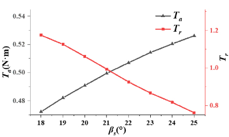
Figure 4: Torque of the initial HESRM.
As shown in Fig. 4, since the torque decrement of the outgoing phase is higher than the torque increment of the incoming phase, the minimum torque value shows up when the electric angle comes to 5∘, 20∘, 35∘ and 50∘. These electric angles show up when the stator pole and the rotor pole start to align. It is clear that if the change of inductance were suppressed, especially at the moment when this alignment starts, the change of transient torque would be reduced and the torque ripple would be thus improved. Consequently, a pole-shoe is suggested on each rotor pole, as shown in Fig. 5.
Machine structure parameters, namely stator pole arc s, rotor pole arc r, pole-shoe length r, and pole-shoe root height h1 selected as optimization variables, are marked in Fig. 5. To study the effect of every structure parameter on torque performance separately, sensitivity analysis was carried out by FEM, in which excitation current remains the same as excitation current in Fig. 4.
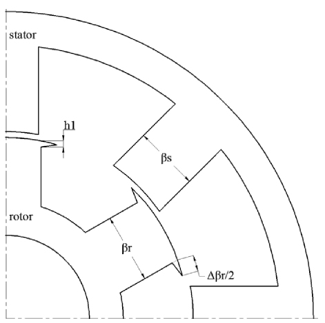
Figure 5: Structure of proposed HESRM.
A. Sensitivity analysis on stator pole arc
We chose to fix the rotor pole arc at 23∘ and increase the stator pole arc from 18∘ to 25∘. The calculated transient torque at every electric position angle is shown in Fig. 6.
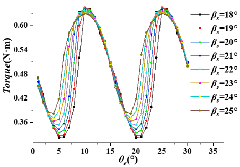
Figure 6: Transient torque at different electric angles.
According to transient torque data in Fig. 6, mean torque in one stroke Ta and torque ripple Tr can be obtained for torque performance evaluation. The torque performance evaluation result is shown in Fig. 7.

Figure 7: Torque performance evaluation under different stator pole arcs.
As the stator pole arc increases, the average torque is increased while the torque pulsation decreases. As shown in Fig. 7, when the stator pole arc is small, the average torque is relatively low and the torque pulsation is large. Excessive stator pole arc will also result in an increased slot fullness. High slot fullness leads to dense windings in the stator slot, making the manufacture and installation of the windings more difficult. It will also lead to poor heat dissipation on phase windings. The increased phase winding temperature will also damage the reliability and life of the motor.
B. Sensitivity analysis on rotor pole arc
We chose to fix the stator pole arc at 21∘ and calculate torque performance under different rotor pole arcs as shown in Fig. 8.
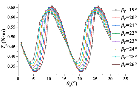
Figure 8: Transient torque under different rotor pole arcs.
As the rotor pole arc increases, the average motor torque will increase while the torque pulsation will decrease. Therefore, a reasonable selection of the rotor pole arc positively increases the average motor torque and reduces torque pulsation. However, the overlarge rotor pole arc also leads to a decrease in motor performance, as shown in Fig. 9. The torque ripple can be increased, and the average torque will be reduced. The increment in the rotor pole arc does not change the motor slot fullness, but it requires more manufacturing materials and weight, which will increase the manufacturing cost.
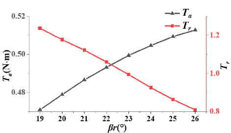
Figure 9: Torque performance under different rotor pole arcs.
C. Sensitivity analysis on pole-shoe
We chose to fix the rotor pole arc of the motor at 23∘ and the stator pole arc at 21∘ so the effect of the pole-shoe on torque performance can be analyzed. The output torque is calculated with different pole-shoe curvatures (r) when the height of pole-shoe h1 is fixed at 1.5 mm, and the calculated result is shown in Fig. 10.
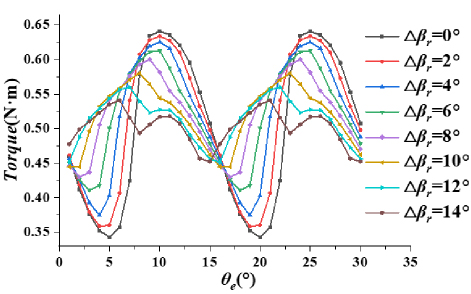
Figure 10: Transient torque with different-length pole-shoes.
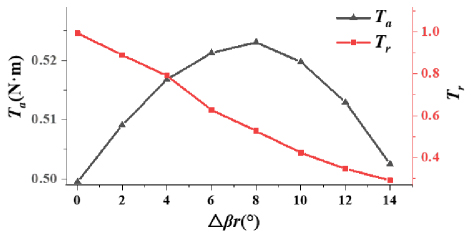
Figure 11: Torque performance under different-length pole-shoes.
As shown in Fig. 11, the increment of r is equivalent to the increase of the rotor pole arc to a certain extent. Moreover, it is more advantageous than increasing the rotor pole arc in terms of cost savings. At the same time, it can appropriately utilize the magnetic saturation phenomenon of the pole-shoe to inhibit the torque change during commutation. As shown in Fig. 11, maximum torque will decrease while minimum torque will first increase with increment of the r.
Torque performance is shown in Fig. 11. As the length of the pole-shoe increases, the average torque motor will decrease while torque pulsation will first increase and then decrease. Therefore, it is important to choose the length of the pole-shoe within an appropriate range to optimize torque performance.
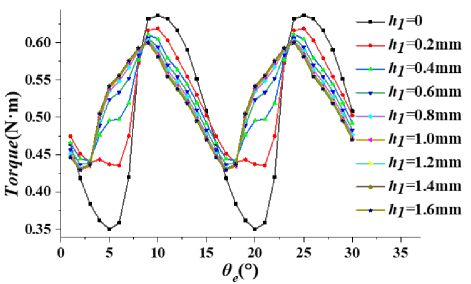
Figure 12: Transient torque under different pole-shoe root heights.
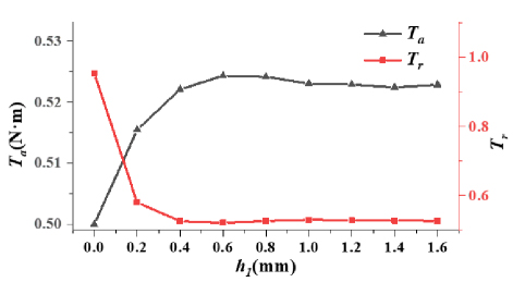
Figure 13: Torque performance under different pole-shoe root heights.
According to Fig. 13, the motor shows relatively good performance at r8∘. While r is fixed at 8∘, torque performance under different pole-shoe root heights (h1) is calculated and shown in Figs. 12 and 13.
As can be seen from Figs. 12 and 13, when h1 is small, torque performance is sensitive to the increase of h1. With the increment of h1, magnetic saturation on the pole-shoe is relieved. When h1 is greater than 0.6 mm, the increment of h1 barely influences the torque performance.
D. Sensitivity analysis on the ratio of DC bias to amplitude of AC component
Composition of the phase current will directly affect the strength and distribution of the magnetic field in the machine. We chose to fix the key parameters of the machine as s20∘, r22∘, r, , h1 are set as 0, RMS value of phase current is limited to 5 A. Transient torque profile under different i0/is is shown in Fig. 14. Corresponding torque performance analysis is shown in Fig. 15.
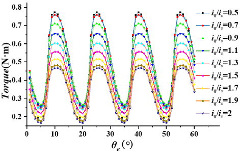
Figure 14: Transient torque profile under different i0/is.
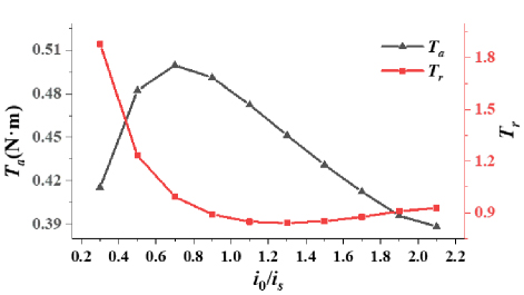
Figure 15: Torque performance under different i0/is.
As shown in Fig. 14, with the increment of i0/is, maximum torque decreases continuously and minimum torque will first rise and then decrease. As shown in Fig. 15, average torque increases and then decreases nearly linearly. Torque ripple will first decrease and then increase significantly. Change of i0/is shows a significant effect on torque and average torque. According to the above analysis, the machine achieves maximum output average torque and shows good torque performance at i0/is0.7. Thus, i0/is0.7 can be fixed for torque performance optimization.
E. Multi-objective evaluations
Average torque and torque pulsation are selected as evaluation objectives. Key structure parameters, marked in Fig. 5, are determined through multi-objective optimization. Nonlinear optimization problems with two evaluation objectives under multiple constraints can be expressed by
| (5) |
where k1 is the weight coefficient of Ta, k2 is the weight coefficient of Tr, X is the set of all variables, and K is the constraint condition as shown in (6). It should be noted here that both torque ripple and average torque are equally important. However, for switched reluctance motors, torque ripple is a more obvious defect and a more critical aspect for improvement. Therefore, in this paper, k10.6 and k20.4 are set. Researchers can flexibly select the weight coefficients they need according to the actual application requirements
| (6) |
According to the constraints and actual limitations, the optimization range of structural parameters is listed in Table 2. The optimization issue is a 4-factor 4-level problem, which contains a total of 16 groups of dimensions. To evaluate as many parameter combinations as possible, an artificial intelligence (AI) based torque prediction model and optimization process is proposed and explained in detail in the next section.
| Parameters | Range |
| r | [13,28] |
| s | [17,26] |
| h1 | [0.3,1.8] |
| r | [6,24] |
IV. AI-BASED PERFORMANCE PREDICTION MODEL AND OPTIMIZATION
Thanks to AI techniques, complicated mathematic problems can be simplified. To solve the optimization problem, an artificial neural network (ANN) based prediction model is built for fast evaluation, and genetic algorithm (GA) is employed for multi-objective optimization. The overall flow chart is shown in Fig. 16. First, a FEM is built to obtain the average torque and torque ripple of the machine. The corresponding torque profile can be found in section II. Then, in the preliminary division, four variables are assigned equidistant, according to the optimization range, with four level values for each variable. Structural parameters are arranged and combined to establish the sample space. GA is employed to optimize the neural network to achieve an accurate predicting model. Finally, GA is employed again to generate the Pareto frontier solution with a well-constructed and trained ANN model. Solutions are evaluated by (5) and the best solution selected.
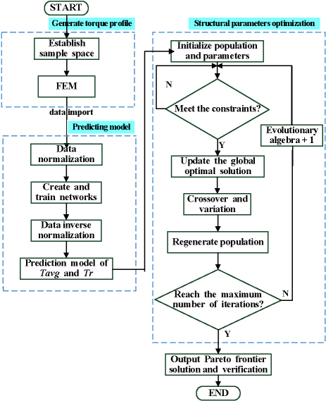
Figure 16: Flow chart of the structural optimization process.
A. Predicting model
To construct an accurate predicting model, GA is employed to search the parameters of ANN. First, set genetic algebra, population size, and other optimization parameters. Then, set boundaries of the optimization variables according to the size of the training data and the structure of the neural network. Next, initialize the population and set the parameters of the optimization function, generate new offspring, and update chromosomes through selection, crossover, and variation. The parameters are decoded and then trained to the neural network model. Subsequently, determine whether the average absolute error is larger, and then determine the number of iterations. If the number of iterations has reached the maximum, the training is completed and the optimized neural network model is obtained. The optimization process of the neural network model is shown in Fig. 17.
The 16 sets of orthogonal experimental data described in the previous section were substituted into the neural network optimized by the GA to establish the training and prediction models.
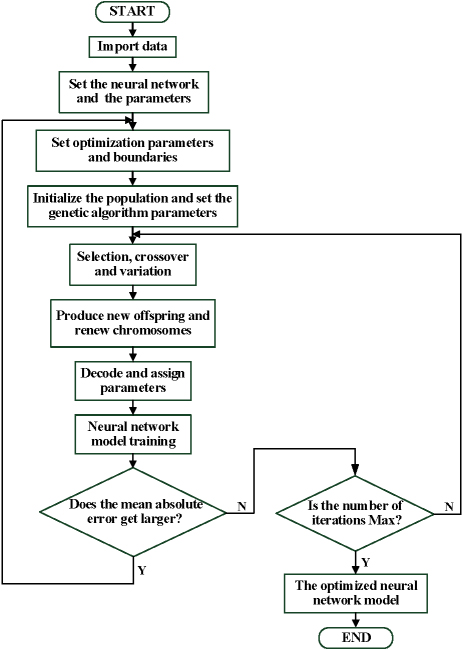
Figure 17: Flow chart of neural network optimization.
B. Structural parameters optimization
To achieve fast and correct optimization, GA is improved by starting the optimization process with multiple starting points. This contributes to avoiding local optimal solutions and reducing the stagnation phenomenon during the search process. In this paper, the population size is set as 100, the maximum number of iterations is set as 50, the variation rate is set as 0.01, and the number of random starting points is set as 30. The Pareto frontier solution of the multi-objective optimization process is obtained after 50 iterations, and the optimization result is shown in Fig. 18.
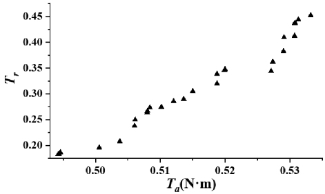
Figure 18: Pareto frontier solutions of multi-objective optimization.
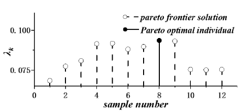
Figure 19: Dominance function values for each Pareto frontier solution.
To avoid the influence of human subjective factors, a fuzzy set, which is generated according to fuzzy theory, is adopted for the final screening of Pareto frontier solutions. Let us define the subordinate function as
| (7) |
where fimax, fimin, and fi is the maximum, minimum, and evaluating values of the ith generations, respectively. For each non-inferior solution k in the Pareto set, the dominating function is defined as
| (8) |
where Mp is the number of Pareto solutions and Nobj is the number of optimization objectives. A higher value of k indicates a better torque performance of structural parameters combination in this solution set. The value of the dominance function of the Pareto frontier solution is shown in Fig. 19.
According to Fig. 19, it can be seen that the 8th individual has the largest value of the dominance function, and the corresponding motor parameters for the 8th individual are shown in Table 3.
Table 3: Motor data before and after optimization
| Parameters | Initial Value | Optimized Value |
| s(∘) | 21 | 24.2 |
| r(∘) | 23 | 14.1 |
| h1(mm) | 0 | 1.75 |
| r(∘) | 0 | 20 |
| Ta | 0.50 | 0.52 |
| Tr | 99.4% | 20.1% |
The optimized data is substituted into the FEA system for verification. In Fig. 20, torque performances before and after optimization are compared. As can be seen in Fig. 20, the average torque of the optimized machine remains approximately the same while the torque ripple is reduced from 99.4% to 20.1%. Comparisons on the two concerned machines are shown in Fig. 21.
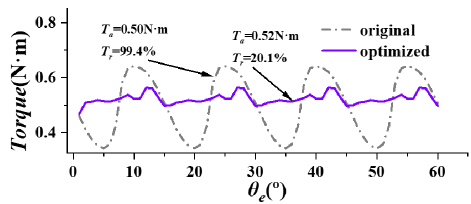
Figure 20: Comparison of torque performance before and after optimization.
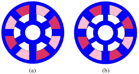
Figure 21: Structure (a) before and (b) after optimization.
V. EXPERIMENTAL VERIFICATIONS
To verify the designed and optimized HESRM, an 8/6 HESRM is made, as shown in Fig. 22. The power converter and control system are shown in Fig. 23.
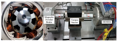
Figure 22: Photograph of 8/6 HESRM.
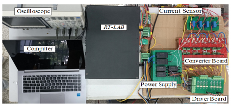
Figure 23: Photograph of the power converter and control system for HESRM.
The transient phase current of HESRM is shown in Fig. 24. In Fig. 25, the measured transient torque is compared with simulation results at 500 rpm, correspondingly. According to the comparison result, the transient torques of the experimental and simulation results are approximately the same, which verifies the accuracy of the finite element analysis.
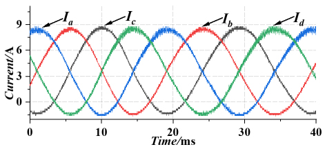
Figure 24: Measured transient phase current.
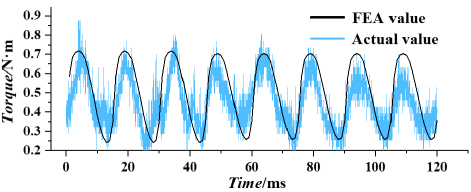
Figure 25: Comparison of measured and calculated transient torque.
In Fig. 26, the effectiveness of the optimization process is verified. As shown in Fig. 26, the average torque of the initial motor is 0.47 Nm, and the torque ripple is 115%. The average torque of the optimized motor is 0.49 Nm, and the torque ripple is reduced to 35.8%. The experimental results show that the optimized motor can significantly reduce torque ripple and provide smoother operation under constant average output torque. Thus, the effectiveness of the multi-objective optimization strategy proposed in this paper can be demonstrated.
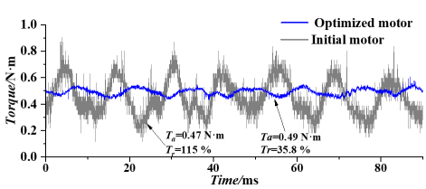
Figure 26: Verification of the effectiveness of multi-objective optimization.
VI. CONCLUSION
In this paper, a four-phase 8/6 HESRM is designed and optimized. The main contributions of this paper can be concluded as follows.
-
The structure of SRM is optimized and the pole-shoe is introduced to improve the torque performance of the switched reluctance motor;
-
FEM is built and key factors that affect the torque performance are analyzed;
-
To achieve a fast and accurate optimization process, an optimization process is proposed. First, a FEM model is built to obtain the torque profile of the machine. Then, a systematic AI-based torque performance model is built for fast torque performance prediction. Finally, GA is introduced to optimize structural parameters with evaluation results generated by the performance predicting model.
-
An experimental prototype is manufactured, to verify the proposed machine structure and optimizing process. Experimental results show that the torque ripple of the prototype is reduced by 79.2% at 500 rpm, which verifies the effectiveness of the optimization method.
As a proof-of-concept, the power and torque of the studied SRM is relatively low. However, the proposed machine structure shows good torque performance and the proposed optimization process can be introduced to other motor optimization projects for further industrial and commercial applications.
REFERENCES
[1] E. Sayed, M. Abdalmagid, N. M. Sa’adeh, A. D. Callegaro, C. Goldstei, and A. Emadi, “Review of electric machines in more-/hybrid-/turboelectric aircraft,” IEEE Transactions on Transportation Electrification, vol. 7, no. 4, pp. 2976-3005, Dec. 2021.
[2] N. Apostolidou and N. Papanikolaou, “Active power control of switched reluctance generator in more electric aircraft,” IEEE Transactions on Vehicle Technologies, vol. 70, no. 12, pp. 12604-12616, Dec. 2021.
[3] P. J. dos Santos Neto, T. A. dos Santos Barros, E. H. Catata, and E. R. Filho, “Grid-connected SRG interfaced with bidirectional DC-DC converter in WECS,” IEEE Transactions on Energy Conversions, vol. 36, no. 4, pp. 3261-3270, Dec. 2021.
[4] P. Yang, W. Shi, Y. Qiu, B. Li, and Y. Gan, “Enhanced efficiency of direct-drive switched reluctance motor with reconfigurable winding topology,” IEEE Access, vol. 10, pp. 62976-62990, 2022.
[5] J. Ye, B. Bilgin, and A. Emadi, “An extended-speed low-ripple torque control of switched reluctance motor drives,” IEEE Transactions on Power Electronics, vol. 30, no. 3, pp. 1457-1470, Mar.2015.
[6] M. V. de Paula, T. A. d. S. Barros, H. S. Moreira, E. O. Hancco Catata, M. G. Villalva, and E. R. Filho, “A Dahlin cruise control design method for switched reluctance motors with minimum torque ripple point tracking applied in electric vehicles,” IEEE Transactions on Transportation Electrification, vol. 7, no. 2, pp. 730-740, June2021.
[7] P. S. Rekha and T. Vijayakumar, “Torque ripple and noise control of switched reluctance motor using an adaptive fuzzy PI control with the aid of AR algorithm,” International Journal of Power Electronics and Drive Systems, vol. 17, no. 5, pp. 1239-1251, 2021.
[8] Y. Rao and L. Jing, “Optimization of hybrid excitation segmented rotor switched reluctance motor based on parameter sensitivity,” Journal of Electrical Engineering & Technology, vol. 17, no. 5, pp. 2899-2907, 2022.
[9] T. Husain, Y. Sozer, and I. Husain, “DC-assisted bipolar switched reluctance machine,” IEEE Transactions on Industry Applications, vol. 53, no. 3, pp. 2098-2109, 2017.
[10] Q. Ma, X. Cui, and L. Zhang, “Torque ripple and acoustic noise of current modulations of a pseudo-sinusoidal switched reluctance motor,” European Conference on Cognitive Ergonomics, pp. 1-5, 2016.
[11] A. Dadpour and K. Ansari, “GA based pole shape optimization for sound noise reduction in switched reluctance motors,” Journal of Soft Computing and Information Technology, vol. 3, no. 4, 2015.
[12] O. Argiolas, E. Nazeraj, O. Hegazy, J. De Backer, A. Mohammadi, and J. Van Mierlo, “Design optimization of a 12/8 switched reluctance motor for electric and hybrid vehicles,” in 2017 Twelfth International Conference on Ecological Vehicles and Renewable Energies (EVER), Monte Carlo, Monaco, pp. 1-10, 2017.
[13] J. T. Shi, X. Liu, D. Wu, and Z. Q. Zhu, “Influence of stator and rotor pole arcs on electromagnetic torque of variable flux reluctance machines,” IEEE Transactions on Magnetics, vol. 50, no. 11, pp. 1-4, 2014.
[14] B. Anvari, H. A. Toliyat, and B. Fahimi, “Simultaneous optimization of geometry and firing angles for in-wheel switched reluctance motor drive,” IEEE Transactions on Transportation Electrification, vol. 4, no. 1, pp. 322-329, 2018.
[15] X. Sun, B. Wan, and G Lei, “Multi-objective and multiphysics design optimization of a switched reluctance motor for electric vehicle applications,” IEEE Transactions on Energy Conversion, vol. 36, no. 4, pp. 3294-3304, 2021.
BIOGRAPHIES

Qing Wang received the B.S. degree in automation from Northeastern University, Shenyang, China, in 2011, and the Ph.D. degree in electrical engineering from China University of Mining and Technology, Xuzhou, China, in 2017. In 2018, he became a Lecturer with the School of Information Engineering, Nanchang University, Nanchang, China, where he has been an Associate Professor since 2023. His research interests include electric vehicles, electrical motor drives, renewable energy generations, and micro-grids.

Jiangtao Hu received the B.S. degree in electrical engineering from Jiangxi University of Science and Technology, Ganzhou, China, in 2023. He is currently working toward the M.S. degree at the School of Information Engineering, Nanchang University. His research interests include power electronics and motor control.

Jiaxin Ding received the B.S. degree in Mechanical from Nanchang University, Nanchang, China, in 2020, and is currently pursuing the M.S. degree in Electrical Engineering at the School of Information Engineering, Nanchang University. His research interests include motor design and control.

Fengshuo Liureceived the B.S. degree in electrical engineering from Henan Polytechnic University, Jiaozuo, China, in 2021. He is currently working toward the M.S. degree at the School of Information Engineering, Nanchang University, Nanchang, China. His research interests include switched reluctance motor and its control.

Yumeng Zhu received the B.S. degree in electrical engineering from East China Jiaotong University, Nanchang, China, in 2023. He is currently working toward the M.S. degree at the School of Information Engineering, Nanchang University. His research interests include power electronics and motor control.

Yongqing Deng received the B.S. and Ph.D. degrees from the School of Electrical Engineering, Wuhan University, Wuhan, China, in 2016 and 2021, respectively. He is currently an Associate Professor with the Information Engineering School of Nanchang University. His main research interests include high voltage and insulation technology, numerical analysis, and engineering application of electromagnetic field.
ACES JOURNAL, Vol. 40, No. 9, 821–830
doi: 10.13052/2024.ACES.J.400903
© 2025 River Publishers