Metamaterial-loaded Circularly Polarized Quad-band SIW MIMO Antenna with Improved Gain for Sub-6 GHz and X-band Applications
R. Anandan, Sathyasri Balasubramanian, Ravi Kumar Sanapala,
and Prakash Kamisetti
1Department of ECE, Dhanalakshmi Srinivasan College of Engineering and Technology
Mamallapuram, Chennai, Tamilnadu, India
anandandscet@gmail.com
2Department of ECE, Vel Tech Rangarajan Dr. Sagunthala R&D Institute of Science and Technology
Avadi Chennai, Tamilnadu, India
dr.sathyasrib@gmail.com
3Department of ECE, St. Martin’s Engineering College
Dhulapally, Secunderabad, Telangana, India
sravikumarece@smec.ac.in
4Department of Electrical and Electronics Engineering, Vaagdevi College of Engineering (UGC Autonomous), Bollikunta, Warangal, Telangana, India
prakashkams@gmail.com
Submitted On: December 31, 2024; Accepted On: May 14, 2025
ABSTRACT
This work presents a quad-band metamaterial-loaded cavity-backed substrate integrated waveguide (SIW) MIMO antenna engineered for sub-6 GHz communication standards such as 5G and WLAN, as well as X-band applications. The use of a cavity-backed SIW architecture enables reduced fabrication complexity and straightforward integration with planar circuits, supporting compact and efficient antenna design. The antenna structure incorporates a modified rectangular split ring resonator (RSRR) slot along with an open-ended rectangular slot embedded within the SIW cavity-backed radiator. This configuration generates four resonant bands operating at 2.4, 3.3, 5.0, and 7.0 GHz. To enhance radiation characteristics, modified RSRR-based metamaterial unit cells are placed along the y-direction in front of the radiating elements. These cells contribute significantly to gain enhancement and enable circular polarization at the designated frequencies. The proposed antenna demonstrates realized gains of 5 dB, 8 dB, 6 dB, and 5 dB at the respective bands, supported by a consistent radiation efficiency of approximately 88%. The antenna also exhibits a stable unidirectional radiation pattern across all operating frequencies, making it suitable for directional multi-port MIMO configurations. To suppress inter-element interference, a cavity-backed parasitic structure is introduced, effectively reducing mutual coupling between radiators. Comprehensive MIMO performance analysis is carried out using standard metrics, including envelope correlation coefficient (ECC), total active reflection coefficient (TARC), channel capacity loss (CCL), and mean effective gain (MEG), confirming strong isolation and diversity capability. Experimental validation aligns closely with simulation results, establishing the proposed antenna’s reliability and potential for use in high-performance, multi-band wirelesssystems.
Index Terms: Cavity-backed SIW, gain enhancement, metamaterial-loaded antenna, quad-band antenna, sub-6 GHz communication.
I. INTRODUCTION
In the current era of wireless communication technology and 5G, where wireless devices are rapidly evolving, there is a significant demand for enhanced data transmission capacity and link reliability [1]. Researchers have suggested multiple approaches to address demand, and MIMO technology has emerged as one of the most effective ways to improve data rates [1]. MIMO antennas, which stand for multiple-input multiple-output, are able to boost channel capacity and link reliability without using additional resources [2]. On the other hand, circularly polarized (CP) antennas effectively battle multipath fading, which results in minimal propagation losses [3]. Because of this, circularly polarized MIMO antennas are essential for the operation of contemporary wireless networks. Circularly polarized wideband MIMO antennas have been developed [3]; nevertheless, circularly polarized multi-band antennas are more appropriate for contemporary communication systems. Numerous methodologies for attaining circular polarization have been reported in the literature. Circular polarization is attained by employing variously shaped slots and the deliberate positioning of a patch on these slots in [4, 5, 6]. The circular polarization is attained via a metamaterial superstate in [7, 8]. Further, to get minimal mutual coupling, high gain, and compact dimensions, numerous design issues must be addressed. In recent years, researchers have introduced various MIMO antennas without circular polarization and with circular polarization in the literature [9, 10, 11, 12, 13, 14, 15, 16, 17, 18, 19, 20, 21, 22, 23, 24, 25, 26].
The substrate-integrated waveguide (SIW) cavity technology has emerged in the last decade, offering various applications and innovative strategies for existing uses. The incorporation of the SIW enables the simultaneous design of an antenna and its corresponding circuitry on a single plane, hence improving dependability relative to conventional circuitry, which occupies limited board space. To enhance the bandwidth of the SIW cavity-backed slot antenna, researchers have explored several ways over severalyears [27, 28].
In environments with significant dispersion, such as industries, a high-gain antenna is essential. The antenna’s gain is improved by the utilization of multi-layer substrates [29], metamaterials [30], and dielectric resonators [31], as reported in the literature. The integration of metamaterials into various antennas substantially enhances antenna gain performance [32]. The metamaterial array is situated in front of the antenna to boost the gain [32, 33]. Furthermore, the antenna gain is enhanced by situating the metamaterial array above the antenna in [34]. The antennas above demonstrate various methods for circularly polarized MIMO antenna implementation, mutual coupling reduction, bandwidth enhancement, and gain enhancement, but few sub-6 GHz MIMO antennas offer a wider bandwidth and higher gain in a compact planar configuration. A metamaterial layer superstate improved gain in stated antennas, but also made them bulky. This paper proposes a sub-6GHzcircularly polarized metamaterial-loaded quad-band cavity-backed substrate integrated waveguide (SIW) MIMO antenna for 5G, WLAN, and X-band applications to address these issues. section II covers MIMO antenna design and development, section III covers experimental results, and section IV covers diversity performance. The proposed antenna is compared to existing works in section-V and concluded insection-VI.
II. MIMO ANTENNA STRUCTURE AND ITS EVOLUTION
A. SIW cavity-backed radiator evolution
The configuration of the proposed SIW cavity-backed slot antenna is depicted in Fig. 1 (a)-(f). The design consists of a square-shaped SIW cavity, formed by the arrangement of metal vias in a square configuration, as illustrated in Fig. 1 (a). The cavity dimensions are determined based on equation (1) and (2), which induce first-order resonance at approximately 5 GHz as depicted in Fig. 2.
| (1) | ||
| (2) |
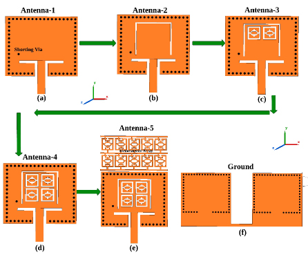
Figure 1: (a)-(f) Development of the proposed SIW cavity backed radiator.
The SIW cavity is created by embedding metal posts within the dielectric substrate, which serves as the lateral conducting walls, as depicted in Fig. 1 (a). The diameter and pitch of metallic vias are determined with the criteria of and to ensure minimal energy loss from the cavity sidewalls. To enhance the bandwidth of the SIW cavity radiator, a shorting pin is positioned 3 mm from the left side of the cavity and 8 mm from the top wall of the cavity, as depicted in Fig. 1 (a). The shorting pins create a short circuit in the current path, resulting in resonance. The enhancement in bandwidth is accomplished by stimulating two hybrid modes: resonance from the SIW cavity and shorting pins positioned in close proximity to each other. Initially, an inverted C-shaped radiating slot has been removed from the center of the SIW cavity, positioned 2 mm from the upper sidewalls and 5 mm from the left and right sidewalls of the cavity, as illustrated in Fig. 1 (b). The positioning of the inverted C-slot has a significant impact on the current path of the first-order resonance mode, resulting in a shift of the corresponding resonant frequency towards the lower end, approximately 3.1 GHz as depicted in Fig. 2. Furthermore, a second-order resonance is generated at 4.1 GHz due to the reactive loading effect of the C-slot, as illustrated in Fig. 2. The integration of the C-slot leads to a decrease in series inductance; however, it simultaneously introduces series capacitance within the cavity circuit.
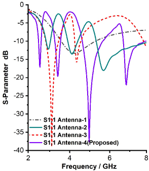
Figure 2: Reflection coefficient of the proposed series-fed dipole radiator.
Further, the two modified SSRR-shaped radiating slots (modified SSRR slot-1 and slot-2) have been removed from the centre of the SIW cavity-backed radiator, positioned at a distance of 2mm from the upper sidewalls of the inverted C-shaped slot and 5mm from the left and right sidewalls of the inverted C-shaped slot, as depicted in Fig. 1 (c). The placement of the C-slot significantly affects the current path for first and second order resonance, resulting in altering the resonant frequencies of 2.9 GHz and 4.4 GHz. The third-order resonance occurs at 5.5 GHz due to the reactive loading effect of the modified SSRR slot-1 and 2 placement, as illustrated in Fig. 2.
Additionally, two modified SSRR-shaped radiating slots (modified SSRR slot-3 and slot-4) have been removed from the centre of the SIW cavity backed radiator, positioned 8 mm from the upper sidewalls of the inverted C-shaped slot and 5 mm from the left and right sidewalls, as depicted in the Fig. 1. The arrangement of the third and fourth modified SSRR-shaped slots significantly change the current pathways of the first, second, and third order mode resonances. Consequently, the resonant frequencies for these modes are adjusted to 2.4 GHz, 3.3 GHz, and 5 GHz, respectively, while the fourth-order resonance occurs at 7 GHz due to the reactive loading effect of the modified SSRR slots 3 and 4, as illustrated in Fig. 2. Ultimately, the proposed radiator, featuring an inverted C-shaped slot and modified SSRR slots, generates four resonance modes at 2.4 GHz, 3.3 GHz, 5 GHz, and 7 GHz, suitable for WLAN, sub-6 GHz 5G, and X-band applications as depicted in Fig. 2.
B. Metamaterial for gain enhancement and circular polarization conversion
The proposed modified SSRR metamaterial units are loaded in-front of the unit cell radiator to improve gain and provide polarization conversion. The proposed modified SSRR unit cell and rectangular connected modified SSRR metamaterial 52 array are depicted in Fig. 3 (a). The proposed metamaterial unit cell consists of a hexagonal shaped ring stub, which is placed inside the the modified SSRR split-ring stub as depicted in Fig. 3 (a). Further, the outer SSRR and inner hexagonal-shaped ring connected through the rectangular-shaped stub as depicted in Fig. 3 (a). The metamaterial used in the proposed design consists of 5 2 modified SSRR unit cells, and all the unit cells are connected using horizontal and vertical rectangular stubs. Further, 5 2 modified SSRR unit cells are printed in front of the antenna in end-fire directions, as illustrated in Fig. 1 (e). The 0.5 mm periodic distance maintained in x- and y-direction between the two modified SSRR unit cells. Performance analysis of the metamaterial is carried out by placing the metamaterial unit cell between two waveguide ports, and different boundary conditions (perfect electric conductor (PEC) and perfect magnetic conductor (PMC)) are applied in x- and y-axis. Further, entire characterization is carried out in CST Microwave Studio software. The y-axis is the direction in which an electromagnetic wave that is propagating normally is directed. On the y-axis, the typical trajectory of the electromagnetic wave’s incidence is aligned with the y-axis. The electromagnetic interactions that take place within the modified SSRR metamaterial unit cell, which are driven by the incident waves, are responsible for the generation of resonance in both the transmitted and reflected waves. The y-axis is responsible for the facilitation of the excitation of the modified SSRR metamaterial unit cell. This is because the electromagnetic wave starts from the SIW cavity-supported antenna and propagates into the unit cells in that direction (y).
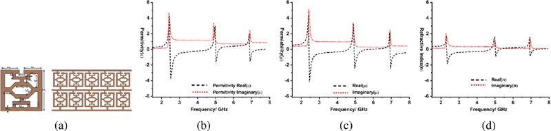
Figure 3: Analysis of the proposed SSRR metamaterial unit cell: (a) Unit-cell structure and metamaterial array, (b) permittivity, (c) permeability, and (d) refractive index.
The permeability, permittivity, and refractive index are critical parameters for precisely evaluating the performance characteristics of the proposed metamaterial unit cell. The permeability, permittivity, and refractive index of the proposed metamaterial unit cell are depicted in Figs. 3 (b)-(d). The figure illustrates that the suggested metamaterial exhibits a negative real near-zero refractive index (NZRI) and epsilon-negative (ENG) characteristics at 2.4, 3.3, 5, and 7 GHz frequency ranges. The findings indisputably illustrate that the proposed SSRR metamaterial exhibits near-zero properties within the operational bands. Consequently, this specific operating frequency zone (2.4, 3.3, 5, and 7 GHz) can be utilized to boost gain and modify the polarization of the proposed antenna.
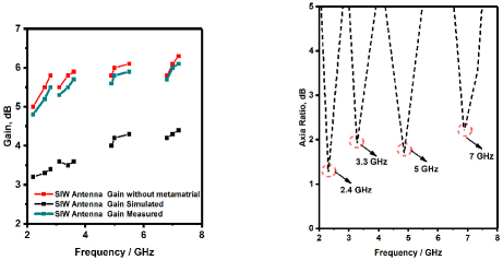
Figure 4: Comparison of (a) Gain and (b) Axial Ratio of the proposed radiator with and without metamaterial.
The gain of the proposed antenna, both with and without metamaterial, is depicted in Fig. 4 (a). Figure 4 indicates that the proposed antenna exhibits gains of 3.3 dB, 2.8 dB, 3.1 dB, and 4.1 dB at frequencies of 2.4 GHz, 3.3 GHz, 5 GHz, and 7 GHz, respectively. The proposed antenna exhibits a gain of 5.5 dB, 8 dB, 6 dB, and 8 dB at frequencies of 2.4 GHz, 3.3 GHz, 5 GHz, and 7 GHz, respectively, subsequent to the incorporation of the metamaterial unit cells. The gain of the proposed antenna with SSRR metamaterial loading has been substantially enhanced without altering the resonant frequencies, as shown in Fig. 4 (a). In addition, metamaterial, in general, has the ability to alter the polarization. The proposed metamaterial unit cells are positioned in front of the antenna in the y-direction, which results in the transformation of the linear polarization into the circular polarization. In addition, the proposed metamaterial is capable of performing the function of a linear-to-circular polarization converter at the 2.4, 3.3, 5, and 7 GHz band, as shown by the axial ratio characteristic depicted in Fig. 4 (b). The axial of ratio of the proposed antenna is greater than three decibels at all of the working frequencies (2.4, 3.3, 5, and 7 GHz), as can be seen in Fig.4 (b).
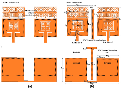
Figure 5: Proposed MIMO antenna (a) without cavity backed parasitic stub decoupling structure, (b) With cavity backed parasitic stub decoupling structure.
C. Two-port MIMO antenna design
The antenna should have a high channel capacity, a high gain, and a good link reliability in order to facilitate communication in an environment that has a significant pathloss owing to scattering. As a result, we suggested the two-port circularly polarized metamaterial-loaded quad-band SIW MIMO antenna for use in sub-6GHz 5G, WLAN, and X-band applications in industries. The proposed circularly polarized MIMO antenna is designed by placing two SIW based metamaterial loaded radiators adjacent to each other, sharing a common ground plane, as illustrated in Figs. 5 (a)-(b).
The dimensions of the proposed MIMO antenna are shown in Table 1. The proposed MIMO antenna with dimensions is depicted in Fig. 5. As depicted in Fig. 5 the side-by-side placement design alleviates the mutual coupling between radiators; however, it is still inadequate for MIMO operation. Therefore, a separate decoupling structure is required to diminish the mutual coupling between the radiators. Consequently, we proposed a SIW cavity-backed parasitic stub decoupling structure. The SIW-based cavity-backed parasitic rectangular stub is positioned on both sides of the substrate, situated between the SIW-based radiator as depicted in Fig. 5. The SIW-based cavity-backed parasitic decoupling structure comprises parasitic rectangular stubs on both sides of the substrate in parallel. The SIW cavity is created by positioning circular shaped vias in a vertical configuration, which connect the front and back conductors as depicted in Fig. 5. The parasitic stub SIW cavity functions as a stop band filter between the radiators of the MIMO antenna. Due to these characteristics, the SIW cavity obstructs the flow of surface current between two simultaneously stimulated radiators. The proposed antenna effectively minimizes mutual coupling between radiating elements through the incorporation of a cavity-backed substrate-integrated waveguide (SIW) decoupling structure. This integrated SIW cavity not only enhances isolation but also preserves compactness, making it highly suitable for multi-port MIMO configurations.
III. EXPERIMENTAL RESULTS AND DISCUSSIONS
A. Reflection coefficient and mutual coupling
The VNA measurement configuration for the proposed MIMO antenna is illustrated in Fig. 6. The comparison of the simulated and measured reflectioncoefficient and mutual coupling of the proposed MIMOantenna is illustrated in Figs. 7 (a)-(b).
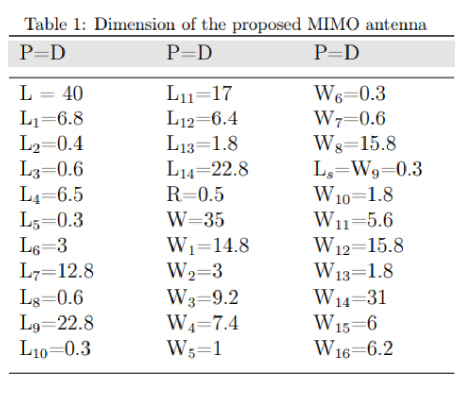
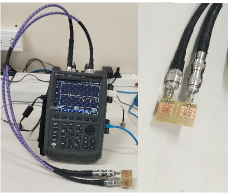
Figure 6: Photograph of the fabricated antenna and measurement setup of the proposed MIMO antenna.
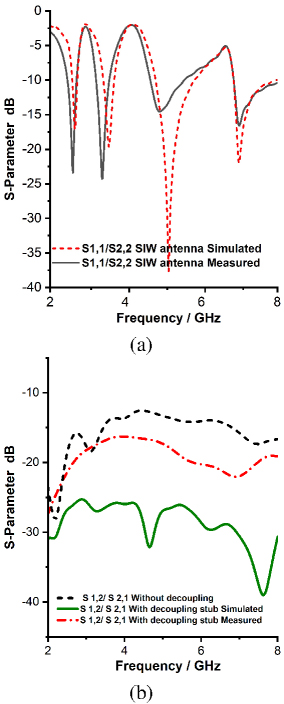
Figure 7: Performance analysis of the proposed MIMO antenna: (a) Reflection coefficient, and (b) Mutual coupling.
Figure 7 (a) illustrates that the proposed MIMO antenna exhibits a reflection coefficient (S11/S22) of less than -10 dB at frequencies of 2.4, 3.3, 5, and 7 GHz, both for the simulated and measured results. Similarly, Fig. 7 (b) illustrates that the proposed MIMO antenna exhibits mutual coupling (S12/S21) of less than -15 dB for frequencies of 2.4, 3.3, 5, and 7 GHz, as evidenced by both the simulated and measured results. The simulated and measured results are in strong agreement.
B. Radiation pattern and efficiency
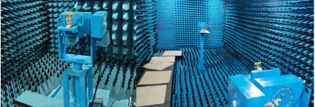
Figure 8: Proposed MIMO antenna’s radiation pattern measurement setup in an anechoic chamber.
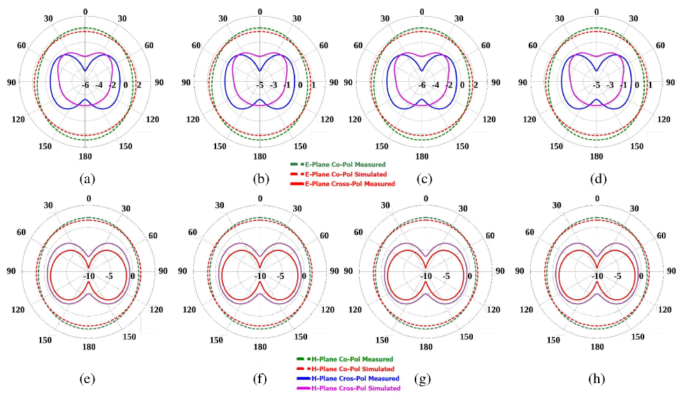
Figure 9: Measured radiation patterns of the proposed antenna showing both co-polarization and cross-polarization components: (a) E-plane at 2.4 GHz, (b) at 3.3 GHz, (c) at 5 GHz, (d) at 7 GHz, (e) H-plane at 2.4 GHz, (f) at 3.3 GHz, (g) at 5 GHz, and (h) at 7 GHz.
The radiation pattern measuring setup of the proposed MIMO antenna is illustrated in Fig. 8. The E- and H-plane 2D cross- and co-polarization radiation patterns of the proposed antenna at 2.4, 3.3, 5, and 7 GHz are depicted in Figs. 9 (a)-(h). Figures 9 (a)-(h) illustrates that the proposed antenna exhibits cross-polarization levels below -10 dB in both the E-plane and H-plane at the operational bands. Additionally, Figs. 9 (a)-(h) illustrate that the proposed antenna exhibits co-polarization levels below -8 dB in both the E-plane and H-plane at the working bands. The proposed MIMO antenna exhibits an omnidirectional radiation pattern across all operational bands (2.4, 3.3, 5, and 7 GHz), as illustrated in Figs. 9 (a)-(h).
The simulated and measured radiation patterns are in strong agreement. The simulated and measured efficiency of the proposed MIMO antenna is depicted in Fig. 10. Figure 10 illustrates that the proposed MIMO antenna exhibits above 90% efficiency across all operational bands (2.4, 3.3, 5, and 7 GHz).
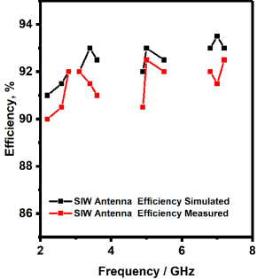
Figure 10: Efficiency of the proposed MIMO antenna.
IV. DIVERSITY PERFORMANCE OF PROPOSED MIMO ANTENNA
The proposed system is assessed using several diversity performance indicators, including ECC, DG, CCL, TARC and MEG.
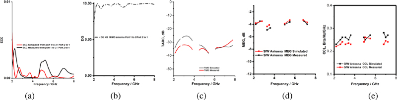
Figure 11: Diversity performance parameters of the proposed MIMO antenna: (a) ECC, (b) DG, (c) TARC, (d) MEG, and (e) CCL.
A. ECC
The envelope correlation coefficient, which is more commonly referred to as the ECC, is a statistical measure that is used to quantify the degree of correlation that occurs between the components of the MIMO antenna.
| (3) | ||
| (4) |
It is feasible to determine it using scattering parameters by using equation (3) in a lossless environment, which is characterized by the uniform distribution of power among antenna elements. However, this equation is only valid in situations when there is no loss. Therefore, the ECC can also be estimated in terms of the emitted far-field by employing Equation 4. In the case of uncorrelated MIMO antennas, the ideal value of ECC is zero. However, for actual MIMO antennas, the ECC value should be less than or equal to 0.5. The ECC proposed MIMO antenna is depicted in Fig. 11 (a). It can be observed from Fig. 11 (a) that the proposed MIMO antenna exhibits an ECC value of less than 0.04 at 2.4, 3.3,5 and 7 GHz.
B. Diversity gain (DG)
Diversity gain, a measure of the enhancement in system performance as a result of the diversity technique, is another essential metric and is computed by equation (5). An improved system’s performance is shown by a larger diversity gain value. Its number should be around 10 for MIMO antenna performance that meets expectations.
| (5) |
The DG of the proposed MIMO antenna is depicted in Fig. 11 (b). It can be observed from Fig. 11 (b) the proposed MIMO antenna exhibits a DG value of almost 10 at 2.4, 3.3, 5, and 7 GHz.
C. TARC
TARC is a statistical measure utilized to accurately evaluate the correlation among the elements of the MIMO antenna. The TARC of the two ports in a MIMO antenna system can be computed using equation (6). The TARC of the MIMO antenna must be below 0 dB for best performance.
| (6) |
The TARC of the MIMO antenna is illustrated in Fig. 11 (c). The Figure 11 (c) demonstrates that the suggested MIMO antenna has a TARC of less than -15 dB. Consequently, the suggested MIMO antennas exhibit less correlation among the radiators.
D. MEG
MEG is another critical statistic for evaluating the performance of MIMO antennas, as it estimates the average received signal strength for each radiator. MEGi denotes the ratio of the mean power received by the ith element to the mean power incident on the jth element from the identical source. MEG can be computed using equation (7), and the MEG value should fall between the range of -3 to 3 for optimal MIMO performance.
| (7) |
Table 2: Comparison of the proposed work with existing work
| Ref. | Total Size (mm3) | Operating Frequency (GHz) | Mutual Coupling (dB) | Peak Gain (dBi) | Efficiency (%) | Decoupling Method | ECC |
| [10] | 48 48 1.6 | 2.25–2.41, 3.36–3.65, 4.7–6.25 | -15 | 1.5–2.9 | 80–88 | Self-isolated | 0.0086 |
| [11] | 25 25 1.57 | 4.36–6.90 | -20 | 2 | 90 | Self-isolated | 0.08 |
| [12] | 25 25 1.57 | 3.4–3.6, 5.15–5.85 | -15 | 2 | 86 | Parasitic stripline | 0.11 |
| [13] | 35 35 1.57 | 3.1–5.2 | -15 | 2.6 | 90 | Self-isolated | 0.05 |
| [35] | 75 150 1.6 (8 elements) | 3.4–3.6 | -15 | 2.5 | 60–70 | Parasitic structure | 0.012 |
| [15] | 40 35 1.6 (2 elements) | 3.5, 5.5, 6.5 | -15 | 3.49 | 80 | Polarization diversity | 0.05 |
| Proposed | 40 35 1.6 (2 elements) | 2.4, 3.3, 5, 7 | -15 | 6.2 | 90 | SIW cavity backed parasitic stub | 0.04 |
The MEG of the MIMO antenna is illustrated in Fig. 11 (c). Figure 11 (c) demonstrates that the suggested MIMO antenna has acceptable MEG values over the operating band.
E. CCL
MIMO antennas are designed to enhance channel capacity. Nevertheless, the correlation among the antenna elements results in losses. CCL, or channel capacity loss, is a metric used to estimate the maximum feasible limit for signal transmission while minimizing significant loss. The calculation of CCL can be performed using equation (E.). The CCL should be maintained below 0.4 Bits/Hz/Sec in practical applications.
| (10) | ||
| (11) | ||
Figure 11 (e) illustrates a representation of the CCL of the MIMO antenna. Figure 11 (e) demonstrates that the proposed MIMO antenna exhibits a CCL of less than 0.4 Bits/Hz/Sec at 2.4, 3.3, 5, and 7 GHz.
V. COMPARISON OF THE PROPOSED WORK WITH EXISTING WORK
A comparison of the performance of the proposed MIMO antenna with that of current MIMO antennas is shown in Table 2. Based on the data presented in Table 2, it is evident that the suggested MIMO antenna is superior to the existing antennas in terms of size, new approach, and gain.
VI. CONCLUSION
This study presents a metamaterial-loaded quad-band cavity-backed substrate integrated waveguide (SIW) MIMO antenna for 5G, WLAN, and X-band applications in the sub-6 GHz region. SIW cavity-backed slot antennas are justified by their reduced fabrication complexity and smooth integration with planar circuits. Four operational bands are created using a modified-RSRR slot and an open-ended rectangular slot on the SIW cavity-backed rectangular radiator. Loading modified rectangular split-ring resonator (RSRR) unit cells in front of the radiators in the y-direction improves the MIMO antenna’s gains by 5 dB, 8 dB, 6 dB, and 5 dB for frequencies of 2.4, 3.3, 5, and 7 GHz. Additionally, loading a modified modified-RSRR produces circular polarization. The cavity-backed antenna creates a unidirectional radiation pattern and reaches 88% efficiency at 2.4, 3.3, 5, and 7 GHz. The proposed MIMO antenna uses a cavity-backed parasitic element decoupling construction to achieve mutual coupling below -15 dB. MIMO characteristics include ECC 0.04, TARC -20 dB, CCL 0.4 bits/Hz/sec, and MEG between -3 dB and 3 dB at 2.4, 3.3, 5, and 7 GHz. Experimental validation of the system confirms its intended functionality, with simulated and measured outcomes in agreement. The proposed antenna is suitable for sub-6 GHz 5G, WLAN, and X-bandapplications.
REFERENCES
[1] A. Kumar, C. S. Rai, and M. K. Khandelwal, “Realization of miniaturized triple-Band four-Port stacked MIMO antenna for WLAN applications at 2.9 GHz, 5.0 GHz, and 5.9 GHz,” AEU – International Journal of Electronics and Communications, vol. 150, p. 154216, 2022.
[2] M. Kaushik, J. K. Dhanoa, and M. K. Khandelwal, “Partially omnidirectional and circularly polarized MIMO antenna covering sub-6-GHz band for 5G fast plan,” IEEE Transactions on Components, Packaging and Manufacturing Technology, vol. 13, no. 9, pp. 1443–1450, 2023.
[3] M. K. Khandelwal, “Metamaterial-based circularly polarized four-port MIMO diversity antenna embedded with slow-wave structure for miniaturization and suppression of mutual coupling,” AEU - International Journal of Electronics and Communications, vol. 121, p. 153241, 2020.
[4] U. Ullah, M. Al-Hasan, S. Koziel, and I. B. Mabrouk, “Series-slot-fed circularly polarized multiple-input–multiple-output antenna array enabling circular polarization diversity for 5G 28 GHz indoor applications,” IEEE Transactions on Antennas and Propagation, vol. 69, no. 9, pp. 5607–5616, 2021.
[5] S. Virothu and M. Satya Anuradha, “Flexible CP diversity antenna for 5G cellular Vehicle-to-Everything applications,” AEU - International Journal of Electronics and Communications, vol. 152, p. 154248, 2022.
[6] U. Sharma, G. Srivastava, and M. K. Khandelwal, “Quad-band two-port MIMO antenna serving for sub-7 GHz frequency with integrated circularly polarized bands,” AEU - International Journal of Electronics and Communications, vol. 160, p. 154503, 2023.
[7] M. Tiwari, K. Afroz, and M. Fatima, “Wideband metasurface loaded circularly polarized MIMO microstrip antenna with high isolation,” Microwave Review, vol. 28, pp. 22–27, 2022.
[8] J. Wang, Y. Cheng, H. Luo, F. Chen, and L. Wu, “High-gain bidirectional radiative circularly polarized antenna based on focusing metasurface,” AEU - International Journal of Electronics and Communications, vol. 151, p. 154222, 2022.
[9] M. Y. Li, Z. Q. Xu, Y. L. Ban, C. Y. D. Sim, and Z. F. Yu, “Eight-port orthogonally dual-polarised MIMO antennas using loop structures for 5G smartphone,” IET Microw. Antennas Propag, vol. 11, pp. 1810–1816, 2017.
[10] P. V. Naidu, M. B. Dhanekula, K. M. Almustafa, A. Kumar, K. A. Meerja, and S. H. Akkapanthula, “Design and performance analysis of MAZE shaped quad port ACS fed tri band MIMO antenna for V2V and multi band applications,” AEU-Int. J. Electron. Commun., vol. 134,2021.
[11] A. Ali, M. E. Munir, M. Marey, H. Mostafa, Z. Zakaria, A. J. A. Al-Gburi, and F. A. Bhatti, “A compact MIMO multiband antenna for 5G/WLAN/WIFI-6 devices”, vol. 14, p. 1153, 2023.
[12] P. V. Naidu, M. B. Dhanekula, K. M. Almustafa, A. Kumar, K. A. Meerja, and S. H. Akkapanthula, “Design and performance analysis of MAZE shaped quad port ACS fed tri band MIMO antenna for V2V and multi band applications,” AEU-Int. J. Electron. Commun, vol. 134, pp. 30–44, 2021.
[13] D. Wu, Y. Qiu, G. Yu, R. Guo, G. Wu, J. Wang, Y. Zhang, M. Zhu, and H. M. Zhou, “Decoupling technique using ferrite-film loading for 5G MIMO applications,” Int. J. Antennas Propag., vol. 45, pp. 1–12, 2022.
[14] A. K. Singh, A. K. Dwivedi, K. N. Nagesh, V. Singh, and R. S. Yadav, “Compact 4‑Port planar MIMO antenna with enhanced isolation for WLAN/WiMAX applications,” Sādhanā, vol. 47, no. 3, p. 138, 2022.
[15] S. B. Paiva, A. G. D. Junior, V. P. S. Neto, and A. G. Assunção, “A new compact dual-polarized MIMO antenna using slot and parasitic element decoupling for 5G and WLAN applications,” Electronics, vol. 11, no. 12, p. 1943, 2022.
[16] J. G. D. Oliveira, A. G. D’assunção Junior, V. P. S. Neto, and A. G. Assunção, “New compact MIMO antenna for 5G, WiMAX and WLAN technologies with dual polarisation and element diversity,” IET Microw. Antennas Propag, vol. 15, pp. 415–426, 2021.
[17] A. Ali, M. E. Munir, M. Marey, H. Mostafa, Z. Zakaria, A. J. A. Al-Gburi, and F. A. Bhatti, “A compact MIMO multiband antenna for 5G/WLAN/WIFI‑6 devices,” Micromachines, vol. 14, no. 6, p. 1153, 2023.
[18] U. Sharma, G. Srivastava, M. K. Khandelwal, and R. Roges, “Shorting pins-based triple band circularly polarized modified monopole compact dual-port MIMO antenna for sub-6 GHz wireless applications,” AEU - International Journal of Electronics and Communications, vol. 176, p. 155162, 2024.
[19] M. Moharana and B. Dwivedy, “Circularly polarized planar antennas with enhanced characteristics for contemporary wireless communication use cases: A review,” IEEE Access, vol. 12, pp. 134594–134613, 2024.
[20] H. Luo, Q. Zhang, G. Sun, H. Yu, and D. Niyato, “Symbiotic blockchain consensus: Cognitive backscatter communications-enabled wireless blockchain consensus,” IEEE/ACM Transactions on Networking, vol. 32, no. 6, pp. 5372–5387, Dec. 2024.
[21] M. Dai, G. Sun, H. Yu, S. Wang, and D. Niyato, “User association and channel allocation in 5G mobile asymmetric multi-band heterogeneous networks,” IEEE Transactions on Mobile Computing, vol. 24, no. 4, pp. 3092–3109, Apr. 2025.
[22] H. Luo, G. Sun, C. Chi, H. Yu, and M. Guizani, “Convergence of symbiotic communications and blockchain for sustainable and trustworthy 6G wireless networks,” IEEE Wireless Communications, vol. 32, no. 2, pp. 18–25, Apr. 2025.
[23] Y. Wang, R. Xiao, N. Xiao, Z. Wang, L. Chen, Y. Wen, and P. Li, “Wireless multiferroic memristor with coupled giant impedance and artificial synapse application,” Advanced Electronic Materials, vol. 8, no. 10, p. 2200370, 2022.
[24] Y. Yao, F. Shu, X. Cheng, H. Liu, P. Miao, and L. Wu, “Automotive radar optimization design in a spectrally crowded V2I communication environment,” IEEE Transactions on Intelligent Transportation Systems, vol. 24, no. 8, pp. 8253–8263, 2023.
[25] X. Zhang, H. Zhang, L. Liu, Z. Han, H. V. Poor, and B. Di, “Target detection and positioning aided by reconfigurable surfaces: Reflective or holographic?,” IEEE Transactions on Wireless Communications, vol. 23, no. 12, pp. 19215–19230, 2024.
[26] H. Chu, X. Pan, J. Jiang, X. Li, and L. Zheng, “Adaptive and robust channel estimation for IRS-aided millimeter-wave communications,” IEEE Transactions on Vehicular Technology, vol. 73, no. 7, pp. 9411–9423, July 2024.
[27] S. Mukherjee and A. Biswas, “Design of planar high-gain antenna using SIW cavity hybrid mode,” IEEE Trans. Antennas Propag, vol. 66, no. 2, pp. 972–977, 2018.
[28] G. Q. Luo, Z. F. Hu, W. J. Li, X. H. Zhang, L. L. Sun, and J. F. Zheng, “Bandwidth-enhanced low-profile cavity-backed slot antenna by using hybrid SIW cavity modes,” IEEE Trans. Antennas Propag, vol. 60, no. 4, pp. 1698–1710, 2012.
[29] H. Liu, H. Tian, L. Liu, and L. Feng, “Co-design of wideband filtering dielectric resonator antenna with high gain,” IEEE Trans. CircuitsSyst. II Express Briefs, vol. 69, pp. 1064–1068, 2022.
[30] C. Shi, J. Zou, J. Gao, and C. Liu, “Gain enhancement of a dual-band antenna with the FSS,” Electronics, vol. 11, no. 18, p. 2882, 2022.
[31] D. C. Lugo, R. A. Ramirez, J. Wang, and T. M. Weller, “Multilayer dielectric end-fire antenna with enhanced gain,” IEEE Antennas Wirel. Propag. Lett., vol. 17, pp. 2213–2217, 2018.
[32] B. A. F. Esmail, S. Koziel, and D. Isleifson, “Metamaterial-based series-fed antenna with a high gain and wideband performance for millimeter-wave spectrum applications,” Electronics, vol. 12, no. 23, p. 4836, 2023.
[33] B. A. F. Esmail, S. Koziel, and A. Pietrenko-Dabrowska, “Wideband high-gain low-profile series-fed antenna integrated with optimized metamaterials for 5G millimeter wave applications,” Sci Rep, vol. 14, p. 185, 2024.
[34] A. Gorai, A. Deb, and J. R. Panda, “Millimeter wave/5G multiband SIW antenna with metasurface loading for circular polarization and bandwidth enhancement,” J Infrared Milli Terahz Waves, vol. 43, pp. 366–383, 2022.
[35] R. Khan, W. T. Sethi, and W. A. Malik, “Enhancing gain and isolation of a quad-element MIMO antenna array design for 5G sub-6 GHz applications assisted with characteristic mode analysis,” Sci Rep, vol. 14, p. 11111, 2024.
BIOGRAPHIES

R. Anandan Associate Professor and Head, Department of Electronics and Communication Engineering, Dhanalakshmi Srinivasan College of Engineering and Technology, ECR, Mamallapuram Chennai, completed his Ph.D. in the Faculty of Information and Communication Engineering from Anna University Chennai in May 2023. His interest includes antenna, optical communication, satellite communication, digital electronics, and wireless communication. He has published seven papers in international conferences and national conferences and four papers in international journals with good impact factors.

Sathyasri Balasubramanian is currently working as Professor in Vel Tech Rangarajan Dr. Sagunthala R & D Institute of Science and Technology, Avadi, Chennai, Tamil Nadu, India. She has a teaching experience of about 21 years in various engineering colleges. Her research interest includes IoT, Health Care, Network Security and Wireless Communication Networks. She has published more than 35 papers in reputed Journals and Conferences. She is a life member of professional organizations such as Indian Society for Technical Education (ISTE) and Senior member of IEEE.

Ravi Kumar Sanapala is currently working as an Associate Professor in St. Martin’s Engineering College, Department of Electronics and Communication Engineering. He has completed M.Tech in Electronics and Communication Engineering from Andhra University College of Engineering, Visakhapatnam, Andhra Pradesh, India in the year 2005. He has successfully completed and awarded his Ph.D. in Electronics and Communication Engineering from Jawaharlal Nehru Technological University, Hyderabad, Telangana. India in 2023. He has 18+ years of teaching experience. He has published more than 30 National, International Conferences and Journals including Scopus and SCI. He has published 10 patents and books in different fields. His area of interest includes Wireless Communication, Radar and Microwave Engineering.

Prakash Kamisetti is working as Professor, Electrical and Electronics Engineering, Vaagdevi College of Engineering, Warangal, India. He has 25 years of experience in teaching and research. He did his B.E. from University of Madras and obtained his MTech and Ph.D. from National Institute of Technology, Warangal. His areas of research are ANN, Meta-Heuristic Techniques, AIML, Smart Grids, Distribution Automationand Distribution System studies. He has published 18 papers in national and international journals. He is a life member of professional organizations such as Indian Society for Technical Education (ISTE) and Senior member of IEEE.
ACES JOURNAL, Vol. 40, No. 8, 724–733
doi: 10.13052/2024.ACES.J.400805
© 2025 River Publishers