Design, Simulation, and Experimental Investigation of a 7.24 GHz Pattern Reconfigurable Monopole Antenna for Enhanced Wireless Communication
Emine Ceren Gözek, Fikret Tokan, Muharrem Karaaslan, and Fatih Özkan Alkurt
1Department of Electronics and Communications Engineering
Yldz Technical University, Esenler, 34220 Istanbul, Turkey
ftokan@yildiz.edu.tr
2Department of Electrical and Electronic Engineering
Kahramanmaras Sutcu Imam University, 46000 Kahramanmaras, Turkey
eminecerengozek@ksu.edu.tr
3Department of Electrical and Electronic Engineering
Iskenderun Technical University, 31200 Hatay, Turkey
muharrem.karaaslan@iste.edu.tr, fozkan.alkurt@iste.edu.tr
Submitted On: January 22, 2025; Accepted On: July 29, 2025
ABSTRACT
This study presents a novel pattern reconfigurable antenna structure designed for wireless communication systems. The proposed antenna operates at a center frequency of 7.2 GHz, which is particularly significant for 5G and future 6G communication systems. This frequency band is suitable for high-speed data transmission and enhances user experience by improving signal quality. The antenna can provide various beam steering capabilities, making it adaptable for multiple applications, including mobile communication systems configurations. The design methodology involves using a circularly grounded monopole antenna. The equivalent circuit models for the RF switches in both open and closed states are provided, facilitating the analysis of the antenna’s electrical characteristics. Simulation and measurement results demonstrate that the antenna maintains a reflection coefficient (|S11|) below -10 dB across a bandwidth of approximately 500 MHz, confirming its wideband performance. The findings indicate that the proposed antenna structure is not only efficient but also adaptable to various operational conditions, making it a promising candidate for future wireless communication applications.
Index Terms: Antenna beamforming, pattern reconfigurability, RF switches, UWB antenna, wireless communications.
I. INTRODUCTION
Reconfigurable antennas play a significant role in wireless communication systems since they can dynamically alter their radiation patterns, frequencies, and polarizations [1, 2]. These antennas achieve reconfigurability through various electronic solutions, including PIN diodes [3], varactor diodes [4], RF-MEMS switches [5], phase shifters, Microwave Liquid Crystal (MLC) technology [6], metasurfaces [7], and optical switches [8].
The advantages of reconfigurable antennas in terms of radiation patterns can be categorized as follows: flexibility, space efficiency, cost-effectiveness, improved signal quality [9], enhanced capacity and coverage [10], and high data transmission rates [11]. These advantages are critically important for meeting the requirements of modern communication systems. One of the fundamental benefits of these antennas is their ability to adjust the radiation pattern according to specific communication scenarios dynamically. This feature enables the antenna to direct signals and avoid interference in crowded environments [12].
When examining the literature on pattern reconfigurable antennas, studies have investigated the ability of antennas designed using RF-MEMS switches to dynamically change their frequency and radiation patterns. Deng et al. state that the Ka-band microstrip patch antenna designed using RF-MEMS switches can achieve reconfigurable radiation patterns. This study demonstrates that RF-MEMS switches can effectively alter the antenna’s radiation pattern [13]. Zhang et al. introduced an innovative approach by presenting a pattern reconfigurable planar array antenna characterized by a digital coding method, which allows for flexible modifications of the antenna’s radiation pattern [14]. Abdulhameed et al. developed a technique to enhance antenna performance by utilizing EBG (Electromagnetic Band Gap) structures and PIN diodes to control the radiation pattern of a microstrip antenna in both elevation and azimuth planes [15]. Jmai et al. noted that their MMIC (Monolithic Microwave Integrated Circuit) antenna design, integrated with RF-MEMS switches, provides reconfigurability for both frequency and radiation patterns [16].
In this study, a novel circularly grounded monopole antenna concept capable of controlling the radiation pattern for wireless communication systems has been designed using RF-MEMS technology, analyzed in a simulation program and experimentally tested. The pattern reconfigurability of the radiation pattern was achieved using 32 RF switches. A microcontroller was employed to monitor the logical states of the electronic components, specifically logic 1 and logic 0, while the surface current density was altered to facilitate the control of the antenna’s radiation pattern. The proposed antenna structure proves the beam steering capabilities of the proposed antenna at 7-7.5 GHz frequency bands.
II. ANTENNA DESIGN METHODOLOGY FOR PATTERN RECONFIGURABLE MONOPOLE ANTENNA
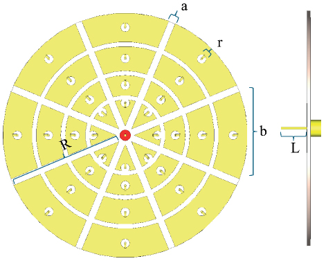
Figure 1: Front and side views of the circular-shaped grounded monopole antenna.
The configuration of the suggested circular monopole antenna is illustrated in Fig. 1, showing both front and side views. The antenna incorporates copper, characterized by an electrical conductivity of 5.8x10⁷ S/m, for its metallic reflectors and ground plane. In contrast, FR-4, a dielectric material with a relative permittivity of 4.3, is utilized as the substrate for the antenna design. The primary purpose of utilizing a circular structure in the design is to take advantage of the fundamental symmetry conditions. The circularly symmetry geometry brings the advantage of direction independence, versatile communication capabilities, wide bandwidth, and polarization diversity. In the circular structure, the central ground is surrounded by 32 identical patch reflectors to control the radiation beams. The beam control is achieved through the logical states of the RF switches, specifically logic 0 and logic 1, which correspond to the on/off states. These antenna dimensions were chosen by considering many factors such as the operating frequency of the antenna and the desired performance characteristics. These dimensions are provided in Table 1.
Table 1: Design parameters of recommended antenna
| Parameter | R | L | r | a | b |
| Dimension | 55 | 18.8 | 4 | 3.06 | 39.25 |
III. SWITCHING TECHNIQUE TO PROVIDE PATTERN RECONFIGURABILITY
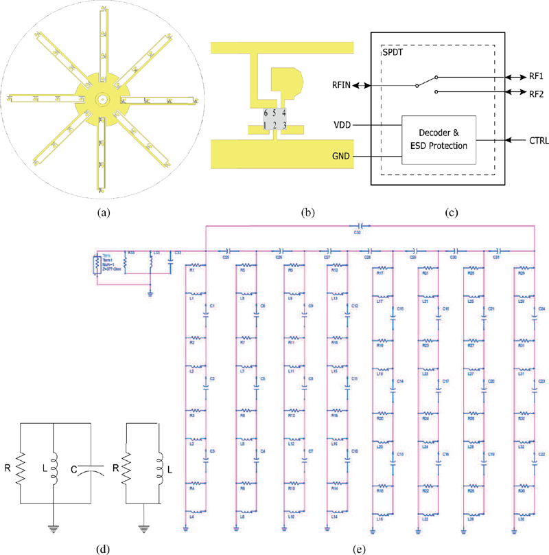
Figure 2: (a) The switching network located in the substrate of the proposed antenna structure, (b) RF switch connection diagram, (c) RF switch block diagram, (d) equivalent circuit model of an RF switch in the on/off-state, and (e) electrical equivalent circuit model of the antenna.
The RF switches (BGS 1 2WN6) operate up to 9 GHz. In Fig. 2 (a), the switching network located in the substrate of the proposed antenna structure is illustrated, showing the connection configuration of 32 RF switches between the reflector and RF ground. Figures 2 (b) and (c) provide detailed connection points for a single RF switch. The design of the antenna allows for the RF current paths in the substrate to change under various switching conditions, depending on the on/off states of the RF switches utilized in the antenna design.
The equivalent circuits for the on/off states of the RF switch used in the proposed antenna structure are shown in Fig. 2 (d). The equivalent circuit model of the complete antenna structure is presented in Fig. 2 (e). These models represent the electrical characteristics of the antenna through a simplified circuit model, which facilitates the analysis of complex antenna structures. This approach enables a better understanding of performance, optimizes the design process, and allows for behavior analysis under different operating conditions. To clarify the derivation of the equivalent circuit model presented in Fig. 2 (e), the RLC (Resistance (R), Inductance (L), and Capacitance (C)) component values were calculated based on the electromagnetic behavior and geometrical configuration of the antenna’s physical structure.
The inductance (L) represents the current paths along the metallic segments of the antenna, and it was approximated using standard inductance expressions for microstrip or wire segments, such as:
| (1) |
The capacitance (C) reflects the coupling between the patch reflectors and the ground plane, and it was estimated using the parallel-plate capacitance model:
| (2) |
where A denotes the effective coupling area and d the vertical separation.
The resistance (R) accounts for conductor losses and is calculated based on the surface resistance Rs. The surface resistance is defined as:
| (3) |
where the skin depth is given by:
| (4) |
This completes the estimation of the RLC parameters based on physical and material properties.
IV. NUMERICAL ANALYSIS FOR THE PROPOSED ANTENNA STRUCTURE
Figure 3 shows the antenna’s reflection coefficient |S11| and the table of switching states when the RF switches are in various switching states. For all switching states, the antenna appears to have a constant |S11| value below -10 dB in the 7-7.5 GHz band. The bandwidth of the antenna structure is 500 MHz.
The working principle of the pattern reconfigurable circular monopole antenna is based on controlling the far-field radiation patterns in the desired direction by dynamically regulating the electromagnetic current paths of the antenna through RF switches. The circular geometry of the antenna consists of multiple segments, which are turned on and off in certain combinations with the utilization of RF switches. Combinations of RF switches modulate the current density and thus the radiation pattern. Depending on the on and off states of the RF switches, the main lobe is formed in a specific (0, 0) direction and ensures that the radiation is limited in that direction.
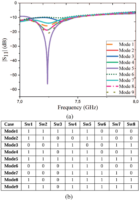
Figure 3: (a) Reflection coefficient of the antenna (|S11|) under various switching conditions characteristics and (b) switching states.
Figure 4 presents various switching conditions of the antenna structure, showing the antenna visuals and simulated 3D and polar radiation patterns for each switching condition. The radiation patterns in polar form were obtained at 7.2 GHz in the =45∘ plane, where maximum radiation occurs. Across all switching conditions, maximum radiation is directed toward the =45∘ plane where the RF switches are closed. This indicates that, by adjusting the necessary switching conditions, it is possible to steer the radiation towards the desired direction.
The total electric field pattern corresponding to each switching state can be generally expressed as:
| (5) |
where is total electric field of the antenna considering to the switching states, Sn= [S1, S2, S3, SN] is switching state (Sn=1 element active, Sn=0 element passive). The radiation function for the antenna structure can be expressed as:
| (6) |
where An is amplitude coefficient of the n element, m determines the magnitude of the main lobe, dn is a distance of n element from the antenna center.
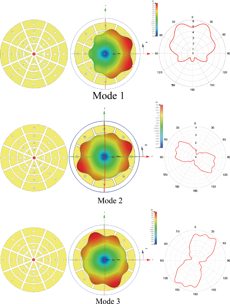
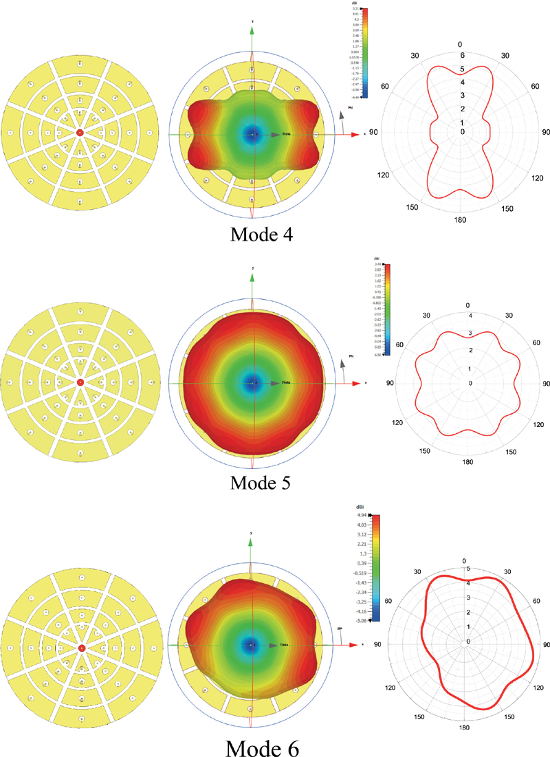
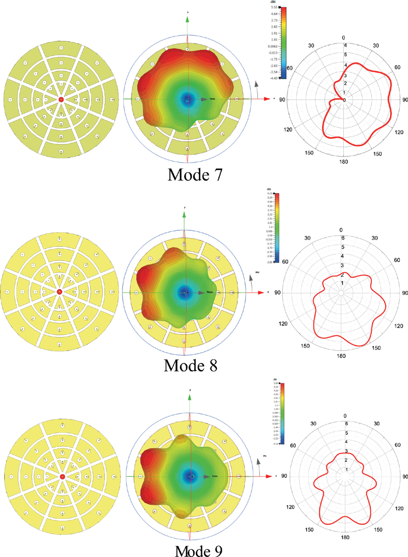
Figure 4: Antenna switching conditions, simulated 3D and polar radiation patterns at =45∘ plane.
The total electric field pattern for the complex radiation function is expressed by:
| (7) |
The term accounts for non-idealities due to environmental effects and is defined as the sum of three main contributions:
| (8) |
where , and , and represent the ground reflection and surface wave effects, mutual coupling effects among antenna elements, and reflection and scattering effects from surrounding objects.
Alternatively, this term can be approximated in a simplified form:
| (9) |
where denotes overall attenuation factor 1 ) and represents the net phase shift from all effects. We define phase angle as:
| (10) |
Finally, the individual radiation pattern of each element is defined as:
| (11) |
The antenna’s ability to direct radiation toward any desired point in different switching states enhances the performance of communication systems, ensures energy efficiency, and increases system flexibility. Considering these advantages, this study enables modern communication systems to operate more effectively and efficiently. Observing the radiation patterns in various switching states, it is evident that the antennas can operate in single, dual, or multiple radiation modes. A single beam allows the antenna to focus in a specific direction, facilitating high-capacity data transfer with maximum energy. In dual-beam steering, the antenna radiates in two different directions, providing a wide coverage area and reducing signal interference, which offers significant advantages.
V. FABRICATION AND EXPERIMENTAL INVESTIGATION
Fabrication of the antenna was carried out in a microwave laboratory using the LPKF-E33 CNC-based printed circuit device shown in Fig. 5 (a). The dielectric material employed was double-sided copper-clad FR4 dielectric material. The monopole structure was fabricated from copper wire. The top and back layers of the produced antenna structure are illustrated in Figs. 5 (b) and (c).
During the simulation phase, the beam steering capability of the antenna was achieved by controlling the on/off states of the RF switches. Each RF switch was positioned between the reflector elements located around the antenna and the ground plane. The on or off state of these switches altered the distribution of surface electromagnetic currents, thereby enabling the formation of beam modes with different radiation directions. As a result, the antenna could produce single, dual, or multi-beam radiation patterns. However, during the fabrication phase, due to the tiny dimensions of the RF switches (approximately 0.71.1 mm2), it was not feasible to directly integrate them into the physical antenna structure. Instead, thin metallic connections were soldered at specific points to emulate the open or closed states of the switches. Through this approach, the switching logic used in the simulation was successfully replicated in the experimental prototype.
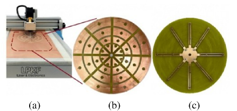
Figure 5: Fabricated antenna structure (a) on LPKF, (b) top view and (c) back view.
|S11| measurements were performed using the Agilent PNA-L vector network analyzer with an operating frequency range of up to 43.5 GHz, as shown in Fig. 6 (a). The reflection coefficient and radiation model measurement setup of the proposed antenna structure are illustrated in Fig. 6 (b). As shown in the radiation model measurement setup, a reference horn antenna was utilized as the receiving antenna, while the fabricated antenna structure served as the transmitting antenna. The reflection coefficient plot of the fabricated proposed antenna structure is presented in Fig. 6 (c) for various switching states. The measured variations with frequency for all combinations show a broadband characteristic of the antenna at the 7.2 GHz center frequency.
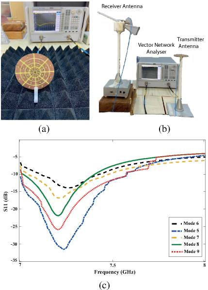
Figure 6: Measurement set up (a) reflection coefficient, (b) radiation pattern, and (c) measured reflection coefficient characteristics.
The measured radiation patterns of the fabricated antenna are presented together with the simulated ones for five randomly selected switching states in Fig. 7. These radiation patterns are almost in good agreement for all selected switching states. However, there are some ignorable mismatches which are caused by laboratory imperfections and using metallic connections in experiments that create insertion loss.
A detailed comparison of the proposed antenna with recent state-of-the-art designs is presented in Table 2, highlighting its distinctive advantages in terms of reconfigurability and design efficiency.
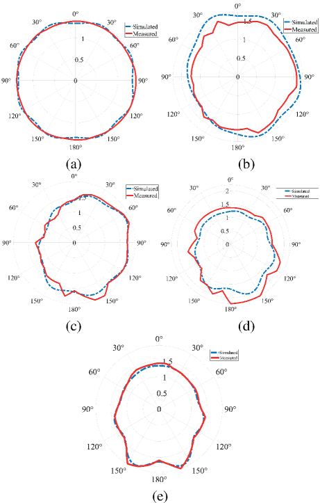
Figure 7: Normalized radiation pattern of polar forms at (a) Mode 5, (b) Mode 6, (c) Mode 7, (d) Mode 8, and (e) Mode 9.
As presented in Table 2, the proposed antenna structure achieves a 16∘ beam steering capability at 7.2 GHz using RF-MEMS switches. Additionally, through various combinations of 32 individually switchable reflector elements, the antenna can generate single, dual, and multi-beam radiation patterns, which enhance energy efficiency, coverage area, and interference mitigation. The most significant distinction of this work from previous studies lies in the antenna’s ability to precisely steer the beam toward a desired direction, which is not only electronically controlled but also mathematically modelled and validated. This feature significantly improves the beam steering performance and facilitates integration into modern wireless communication systems.
Table 2: Literature comparison
| Ref. | Switching Element | Frequency (GHz) | Beam Steering Range | Reconfig-urability Type |
| [13] | RF-MEMS | 35 | 16∘ | Pattern |
| [15] | PIN Diode | 6 | 40∘ | Pattern |
| [16] | RF-MEMS | 26-30.7 | - | Frequency |
| [17] | PIN Diode | 1.57-2 | 84∘ | Pattern |
| This Work | RF-MEMS | 7.2 | 16∘ | Pattern |
VI. CONCLUSION
This study comprehensively examines the significance and potential of the novel circularly grounded monopole antenna in wireless communication systems. The proposed antenna structure designed using RF switches offers a critical advantage for meeting the requirements of modern communication systems by enabling dynamic adjustment of radiation patterns. The findings indicate that at a frequency of 7.2 GHz, the maximum radiation intensity occurs at an =45∘ direction when all RF switches are in the off position. This demonstrates the capacity of the proposed antenna to steer radiation toward desired directions by adjusting the switching conditions.
The antenna, operating in different switching states, exhibits single, dual, and multi-beam radiation modes, enhancing communication system performance and ensuring energy efficiency. The ability to form a single beam allows the antenna to focus on a specific direction, offering high data transfer capacity. In contrast, dual-beam steering provides significant advantages such as broad coverage and reduced signal interference.
In conclusion, the designed pattern reconfigurable antenna, with its flexibility, cost-effectiveness, and high data transmission speed, can significantly improve communication system performance and enhance user experience. The proposed antenna can be applied in 5G and 6G wireless communication systems and the Internet of Things. Future research should focus on frequency and polarization reconfigurability.
REFERENCES
[1] T. A. Elwi, F. Taher, B. S. Virdee, M. Alibakhshikenari, I. G. Zuazola, A. Krasniqi, A. S. Kamel, N. T. Tokan, S. Khan, and N. O. Parchin, “On the performance of a photonic reconfigurable electromagnetic band gap antenna array for 5G applications,” IEEE Access, vol. 12, pp. 60849-60862,2024.
[2] N. Ojaroudi Parchin, H. Jahanbakhsh Basherlou, Y. I. Al-Yasir, R. A. Abd-Alhameed, A. M. Abdulkhaleq, and J. M. Noras, “Recent developments of reconfigurable antennas for current and future wireless communication systems,” Electronics, vol. 8, no. 2, p. 128, 2019.
[3] E. C. Gözek, F. Tokan, and M. Karaaslan, “Frequency reconfgurable lbra shape antenna for mmW 5G communcatons,” Journal of Infrared, Millimeter, and Terahertz Waves, vol. 46, no. 7, pp. 1-16, 2025.
[4] Y. Mu, J. Han, D. Xia, X. Ma, H. Liu, and L. Li, “The electronically steerable parasitic patches for dual-polarization reconfigurable antenna using varactors,” Applied Computational Electromagnetics Society (ACES) Journal, vol. 37, no. 1, pp. 58-67, 2022.
[5] W. M. Abdulkawi, A.-F. A. Sheta, W. A. Malik, S. U. Rehman, and M. S. Alkanhal, “RF MEMS switches enabled H-shaped beam reconfigurable antenna,” Applied Computational Electromagnetics Society (ACES) Journal, vol. 34, no. 9, pp. 1312-1319, 2019.
[6] S. Ma, X.-N. Li, Z.-D. Li, and J.-J. Ding, “Electronic beam steering metamaterial antenna with dual-tuned mode of liquid crystal material,” Sensors, vol. 23, no. 5, p. 2556, 2023.
[7] G. Liu, C. Ju, Z. Li, Z. Yang, X. Qu, N. Liu, and W.-H. Zong, “A low-profile wideband pattern reconfigurable antenna with metasurface,” Applied Computational Electromagnetics Society (ACES) Journal, vol. 39, no. 10, pp. 868-875, 2024.
[8] L. Silva, A. Alves, and A. Cerqueira Sodré Jr, “Optically controlled reconfigurable filtenna,” International Journal of Antennas and Propagation, vol. 2016, no. 1, p. 7161070, 2016.
[9] A. H. Moore, S. Hafezi, R. R. Vos, P. A. Naylor, and M. Brookes, “A compact noise covariance matrix model for MVDR beamforming,” IEEE/ACM Transactions on Audio, Speech, and Language Processing, vol. 30, pp. 2049-2061, 2022.
[10] M. Rihan, T. A. Soliman, C. Xu, L. Huang, and M. I. Dessouky, “Taxonomy and performance evaluation of hybrid beamforming for 5G and beyond systems,” IEEE Access, vol. 8, pp. 74605-74626, 2020.
[11] J. Oh and K. Sarabandi, “Compact, low profile, common aperture polarization, and pattern diversity antennas,” IEEE Transactions on Antennas and Propagation, vol. 62, no. 2, pp. 569-576, 2013.
[12] K. Li, Y. M. Cai, Y. Yin, and W. Hu,” A wideband E-plane pattern reconfigurable antenna with enhanced gain,” International Journal of RF and Microwave Computer-Aided Engineering, vol. 29, no. 2, p. e21530, 2019.
[13] Z. Deng, Y. Wang, and C. Lai, “Design and analysis of pattern reconfigurable antenna based on RF MEMS switches,” Electronics, vol. 12, no. 14, p. 3109, 2023.
[14] X. G. Zhang, W. X. Jiang, H. W. Tian, Z. X. Wang, Q. Wang, and T. J. Cui, “Pattern-reconfigurable planar array antenna characterized by digital coding method,” IEEE Transactions on Antennas and Propagation, vol. 68, no. 2, pp. 1170-1175, 2019.
[15] M. Abdulhameed, M. Isa, Z. Zakaria, I. Ibrahim, and M. K. Mohsen, “Radiation pattern control of microstrip antenna in elevation and azimuth planes using EBG and pin diode,” International Journal of Electrical & Computer Engineering, vol. 9, no. 1, p. 332, 2018.
[16] B. Jmai, S. Gahgouh, and A. Gharsallah, “A novel reconfigurable MMIC antenna with RF-MEMS resonator for radar application at K and Ka bands,” International Journal of Advanced Computer Science and Applications, vol. 8, no. 5, pp. 468-473, 2017.
[17] W. M. Abdulkawi, W. A. Malik, A. F. A. Sheta, and M. A. Alkanhal, “A compact dual circular patch pattern reconfigurable antenna,” Microwave and Optical Technology Letters, vol. 60, no. 11, pp. 2762-2768, 2018.
BIOGRAPHIES

Emine Ceren Gözek is currently pursuing a doctoral education in the Communication Department of the Electronics and Communication Engineering program at Y ld z Technical University, Istanbul, Turkey. Simultaneously, she is a research assistant at Kahramanmaraş Sütçü Imam University. Her research interests include reconfigurable antenna, applications of metamaterials, electromagnetic waves and propagation.

Fikret Tokan received his Ph.D. degree from Y ld z Technical University, Istanbul, Turkey, in Communication Engineering in 2010. From October 2011 to October 2012, he was a Postdoctoral Researcher in the EEMCS Department of Delft University of Technology. From October 2012 to May 2013, he was a Postdoctoral Fellow at the Institute of Electronics and Telecomm. (IETR), University of Rennes 1, France. Since September 2002, he has worked in the Electromagnetic Fields and Microwave Technique Section of the Electronics and Communications Engineering Department of Y ld z Technical University. He is currently working as a professor in that department. His current research interests are UWB antenna design, dielectric lens antennas, reflector systems, electromagnetic waves, propagation, antenna arrays, scattering, and numerical methods.

Muharrem Karaaslan received the Ph.D. degree in physics from the University of Cukurova, Adana, Turkey, in 2009. He has co-authored almost 200 scientific contributions published in journals and conference proceedings. His research interests include the applications of metamaterials, analysis and synthesis of antennas, and waveguides.

Fatih Özkan Alkurt received the Ph.D. degree in electrical and electronics engineering from the Iskenderun Technical University, Turkey, in 2024. He was awarded the 2024 Excellence in Electrodynamics Award. His research interests include antenna designs, microwave transmission lines and metamaterials.
ACES JOURNAL, Vol. 40, No. 8, 734–744
doi: 10.13052/2024.ACES.J.400806
© 2025 River Publishers