Compact Bandpass Filter for Ultra-wide Stopband Rejection
Pritha Narayanan and Maheswari Shanmugam
1Faculty of Information and Communication Engineering
Anna University, Chennai 600025, Tamil Nadu, India
prithabe28@gmail.com
2Department of Electronics and Communication Engineering
Panimalar Engineering College, Chennai 600123, Tamil Nadu, India
maheswarisp@yahoo.co.in
Submitted On: January 30, 2025; Accepted On: June 28, 2025
ABSTRACT
The design objectives for a bandpass filter intended for modern wireless applications include achieving wide stopband attenuation and preserving signal strength within the passband. The proposed architecture aims to provide an effective solution for WLAN systems by minimizing insertion loss while sustaining other essential performance parameters. An asymmetric-short to the stepped impedance resonator (ASSIR) bandpass filter is presented. The second-order end coupled filter is initially designed, and transmission zeros and resonance frequencies are mathematically derived using ABCD parameters and odd and even mode calculations, respectively. A middle-short is introduced to the resonators to increase the depth of transmission zeros at the band edges. Further, an asymmetric-short to the resonators, along with stubs at the feed lines, is incorporated to realize an ultrawide stopband until 12.8 GHz and also to achieve compactness of 0.3g0.18g without modifying the structure. The low-cost FR4 substrate , simple end-coupled ASSIR bandpass filters is mathematically verified, simulated and measured at 2.45 GHz with an in-band low insertion loss of 1.4 dB.
Index Terms: Asymmetric-short, bandpass filter, middle-short, stepped impedance resonator.
I. INTRODUCTION
In today’s widely congested electromagnetic spectrum, microwave bandpass filters (BPFs) are essential RF devices to perform signal selection and out-of-system interference mitigation simultaneously. Different architectures for size reduction, extended stopband, and high gain are necessary for upgrading the overall system performance.
The empirical formula for parallel coupled stepped impedance resonator design in [1] deals with the arbitrary coupling length of the resonator and quarter wavelength coupling to control spurious response and insertion loss. The analysis of fundamental characteristics of various wavelength stepped impedance resonators, such as equivalent circuit, spurious response, resonance conditions, and resonator length, is presented in [2] whose practical applications are reported. The bandpass filters with various coupling and odd and even mode impedance are presented in [3]. The relationship between transmission zeros and the position of feed lines is discussed in [4] for a microstrip filter.
The spurious modes of the stepped impedance resonator [5] are analyzed based on length and impedance ratios to extend the rejection in stop band. The resonators [6] are selected in such a way to get a fixed fundamental frequency but with different spurious frequencies in order to suppress spurious signals. A lowpass filter [7] with both end and parallel coupling is designed with slow wave effect to obtain both compactness and suppression of spurious signals. A meandered resonator loaded with a shorted stub is presented in [8] for compact size, wide stop band and better selectivity.
II. LITERATURE REVIEW
Coupled line filters in [9] and cross-structured resonators with coupled lines are reported in [10] for miniaturization in size, but trade-offs between key characteristics such as insertion loss and stopband rejection need to be considered for the filter design. Resonators in the shunt branch of elliptic filters in [11], pairs of coupled lines in [12], a pair of resonators with different resonance frequencies in [13], and a coupled line-stub cascaded structure in [14] are used for generating required transmission zeros to realize out-of-band suppression and deep roll-off skirts. A minimum degree of attenuation is achieved in the stopband.
The quasi-elliptic bandpass response obtained in [15], a filter with stepped impedance stubs [16], stepped impedance resonator-based coupled lines in [17], and various slots and open stubs used in substrate-integrated waveguide (SIW) structure [18] improve frequency selectivity by placing transmission zeros near the passband while limiting attenuation over the wide stopband. Middle-shorted hairpin resonators in [19], short-circuited stub-embedded ring resonators in [20], inter-resonance in post-loaded SIW resonators described in [21] and adjustable transmission zeros achieved by modifying length of the apertures embedded in SIW [22] are employed to realize a wide stopband but use complex design topology. Substrate integrated waveguide-based filters using rectangular slots in two quarter-mode cavities [23] focus on suppressing the second mode and lowering the third mode’s coupling to improve stopband rejection, but this results in minimum rejection.
In the proposed work, an end-coupled stepped impedance resonator-based bandpass filter is initiated to analyze transmission zeros and resonance frequencies. To the best of our knowledge, developing a filter with a wide stopband and compact size remains a challenging task. The end-coupled bandpass filter with asymmetric-short resonators with open stubs is proposed to offer lower insertion loss, harmonic suppression in the stopband, and compact size.
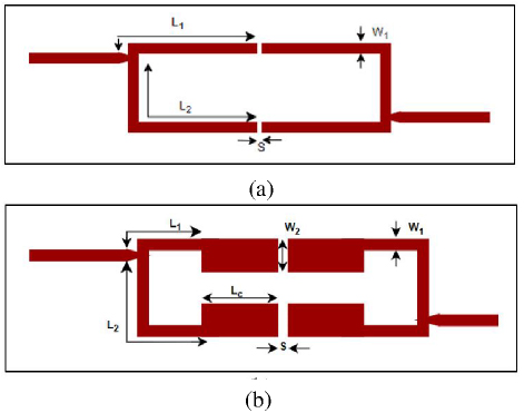
Figure 1: (a) Layout of UIR BPF with end coupling. Dimensions are L113.2 mm, L219.4 mm, W11.2 mm, S0.3 mm and (b) Layout of SIR BPF with end coupling. Dimensions are L14.2 mm, L212.0 mm, Lc4.8 mm, W11.2 mm, W23.7 mm, S0.3 mm.
III. BASIC DESIGN: END-COUPLED UNIFORM IMPEDANCE RESONATOR
Generally, uniform impedance resonators (UIR) are folded to get compactness in the filter. Two folded resonators are connected electrically with end coupling, as shown in Fig. 1 (a). The relation between feed lines and transmission zeros, both symmetric and asymmetric feed line positions, is analyzed in [4] using an ABCD matrix.
IV. ANALYSIS OF END-COUPLED STEPPED IMPEDANCE RESONATOR
The design consists of two half-wavelength stepped impedance resonators (SIR). One resonator is coupled to another resonator through a gap, forming an end-coupled structure. The gap between the resonators is modelled as a capacitor. Figure 1 (b) shows the stepped impedance resonator BPF with end coupling. Thus, the coupling at the ends of these two resonators evolves into a bandpass filter to achieve basic performance metrics. Adjustable feed line tapping is utilized to shape the passband of the filter.
A. Location of transmission zeros
From the position of the feed line, the frequencies of the transmission zeros are expressed mathematically. As described in [4], the connected shunt circuit is segmented into upper and lower sections. Each section of SIR is expressed in ABCD matrices, where is the electrical length of high impedance line in the upper part, the length of the high impedance line in the lower part, the length of low impedance line, and is the end coupling modelled as capacitor.
The upper part of coupled structure is expressed as:
| (3) | |
| (6) |
The lower part of coupled structure is expressed as:
| (9) | |
| (12) |
The upper and lower sections of the ABCD parameters are converted to admittance parameters and added to get the total admittance parameters. From the total admittance parameters, can be calculated as:
| (13) |
As C is very small, the equation is reduced to:
| (14) |
The equation is further simplified as:
| (15) |
and:
| (16) |
Therefore, the frequency of transmission zeros corresponding to feed positions is expressed in terms of electrical length and impedance. By solving equations (1-6), the transmission zeros for the end coupling BPF are expressed. From the equation, the relation between transmission zeros and feed positions is calculated for the filter. The calculated transmission zeros are 1.94 GHz and 3.23 GHz, and the equations closely match the simulation results. As the half-wavelength resonator is folded, the position of the feed line determines the frequency of transmission zeros. Further, the analysis focused on the fact that the frequency of transmission zeros not only depends on the electrical length but also on the impedance ratio of the stepped impedance resonator.
B. Resonance conditions
The resonant frequency of a stepped impedance resonator is described using electrical length and impedance ratio, which act as deciding factors. Various combinations of impedance ratios are used in the design of the resonator to observe that it exerts control over shifting the odd and even modes to higher and lower frequencies, respectively. Also, a noticeable change in the impedance ratio makes the electrical length change in order to achieve compactness in the structure. The circuit is decomposed into odd and even mode circuits, which are shown in Figs. 2 (a) and (b).
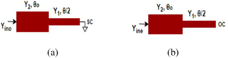
Figure 2: (a) Odd mode and (b) Even mode conditions.
The input admittance of the circuit is:
| (17) |
The coupling between the SIRs is assumed to be infinite or large. The resonant frequencies of two modes are derived as follows.
The admittance at the short circuit is:
| (18) |
By substituting equation (18) into equation (17), the odd mode input admittance is derived as:
| (19) |
By substituting=0, the equation for the odd mode resonance becomes:
| (20) |
The odd mode resonance frequency is obtained from equation (20) for the total electrical length of as pointed out in Fig. 2. Similarly, the admittance at the open circuit is:
| (21) |
By substituting equation (21) into (17), the odd mode input admittance is:
| (22) |
By substituting=, the equation for the even mode resonance becomes:
| (23) |
The even-mode resonance frequency is obtained from equation (23) with K .
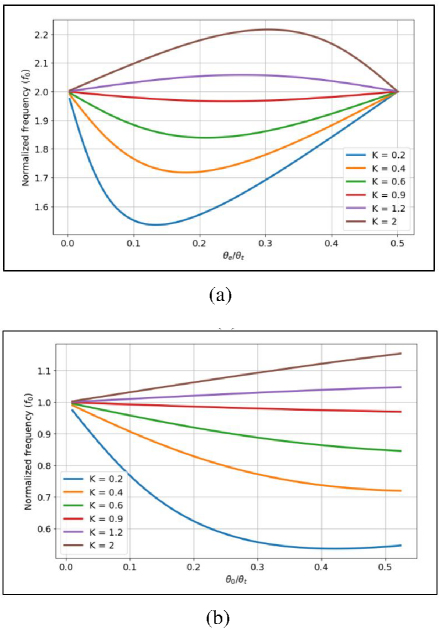
Figure 3: (a) Calculated odd mode resonance with various K values and (b) Even mode resonance with various K values.
The fundamental mode and lowest spurious mode of the end-coupled stepped impedance resonator are observed using odd mode and even mode, respectively. Both transmission zeros and resonance equations depend directly on parameters related to impedance ratios and electrical length ratios. The fundamental mode frequency is 2.45 GHz, calculated from equation (20). The lowest spurious mode frequency is 5.13 GHz from equation (23) for K 0.55 and 0.280. From the equations, the odd and even mode resonances are plotted between the normalized frequency and the electrical length ratio with various values of K, as shown in Figs. 3 (a) and (b).
The fundamental and first spurious signals are shifted to lower frequencies, and the second and third spurious signals are shifted to higher frequencies, as shown in Fig. 4 (a), with K varying from 1 to 0.2. The fundamental and first spurious signals are shifted to higher frequencies, and the second and third spurious signals are shifted to lower frequencies, as shown in Fig. 4 (b), with K varying from 1 to 4. Both odd and even mode resonances are shifted and controlled by various K values. The resonance calculated by the theoretical equations matches well with the simulated odd and even mode resonances and their response to various K values. K 1 is treated as a reference and hence highlighted in Figs. 4 (a) and (b).
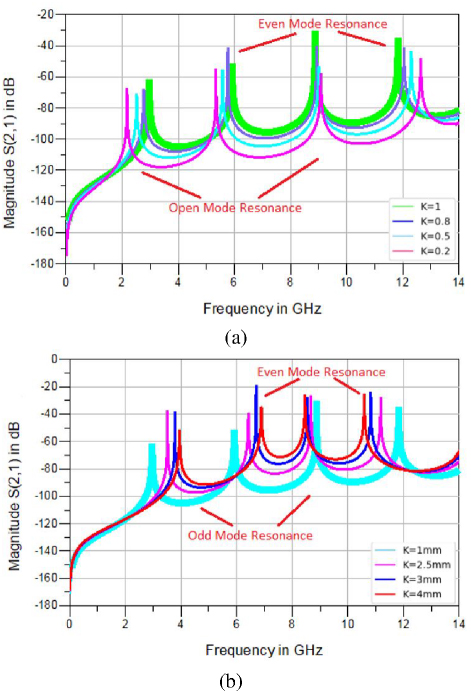
Figure 4: (a) Simulated response of SIR for various K values from 1 to 0.2 and (b) various K values from 1 to 4.
The coupling coefficient (k) and external quality factor (Qe)are calculated from equations (24) and (25):
| (24) | ||
| (25) |
The calculated coupling coefficient k between the resonators is 0.23, and the external quality factor Qe of the filter is 5.06, as identified in the plots shown in Figs. 5 (a) and (b).
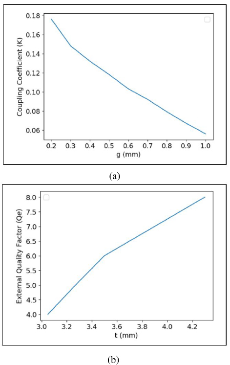
Figure 5: (a) Coupling coefficient k versus gap between the resonators g and (b) External quality factor Qe versus tapping position t.
V. PROPOSED DESIGN
A. Middle-short-stepped impedance resonator (MSSIR) bandpass filter
The performance of a stepped impedance bandpass filter with end coupling, such as in-band insertion loss and harmonic suppression, is improved by introducing a middle-short into the resonators.
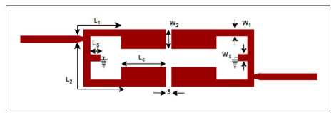
Figure 6: Layout of end-coupled MSSIR BPF. Dimensions are L1 4 mm, L212.4 mm, Lc4.2 mm, LS2.1 mm, W1WS1.2 mm, W23.7 mm, S0.3 mm.
In the end-coupled stepped impedance bandpass filter, the characteristics are redefined by introducing a middle-short, as shown in Fig. 6.
A middle-short half-wavelength resonator behaves like a quarter-wavelength resonator, which naturally rejects even harmonics. Therefore, a middle-short along with end coupling improves bandwidth with selectivity, reduces in-band insertion loss at the center frequency, and extends harmonic suppression with better attenuation in the stopband. The circuit is decomposed to odd and even mode circuits are shown in Figs. 7 (a) and (b).
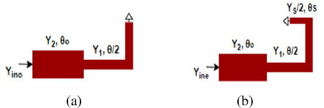
Figure 7: (a) Odd mode and (b) Even mode conditions.
The resonant frequencies of two modes are derived as follows. After introducing a middle-short, no change in the odd mode resonance; then the equation is:
| (26) |
For even mode resonance, the following conditions are used. The admittance at the short circuit is:
| (27) |
The intermediate input admittance between and is:
| (28) |
The intermediate input admittance between and is:
| (29) |
Solving equations (17-19), and substituting=, the equation for the even mode resonance becomes:
| (30) |
The even-mode resonance frequency is obtained from equation (A.).
The calculated odd-mode resonance from equation (26) is 2.45 GHz, the same as the SIR BPF with end coupling. The calculated even mode resonance from equation (A.) is 7.57 GHz, which justifies the quarter-wavelength resonator behavior due to the extended stub with a short at the middle of the resonators. The addition of middle-short resonators improves the filter’s selectivity. This minimizes interference from neighboring transmissions and enables the exact filtering of specific frequencies. The design reduces undesired frequencies and provides an extended stopband, which helps to improve signal isolation. This increases the applicability of the filter and makes it more flexible in a variety of communication applications. The exceptional feature of the filter topology is that it produces strong out-of-band rejection without the need for extra components, which is one of its main advantages. This helps to make the overall design simpler, easier to implement, and moreaffordable.
B. Asymmetric-short-stepped impedance resonator bandpass filter
The characteristics of a stepped-impedance resonator are further improved by incorporating an asymmetric-short. A middle-short to the resonator improves the out-of-band rejection but fails to preserve the insertion loss at the center frequency and also bandwidth. Good passband bandwidth along with low insertion loss can be preserved by shifting the short stub slightly from the center of the resonator, creating an asymmetric-short to the resonator as shown in Fig. 8. By adjusting the position of the short stub from the center of the resonator, an unintentional slight shift in harmonics to higher frequencies is obtained.
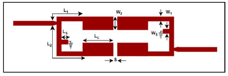
Figure 8: Layout of end-coupled ASSIR BPF. Same as dimensions used in MSSIR BPF.
Two stubs are introduced at the feed lines to improve stopband rejection in combination with an asymmetric-short resonator. The equations for the length of the stubs are given in [4], determined from equations (25) and (16). The selected lengths are used to obtain transmission zeros at 7.52 GHz and 9.41 GHz:
| (15) | ||
| (16) |
The fabricated design of an asymmetric-short to the stepped impedance resonator (ASSIR) BPF is shown in Fig. 9 with stubs, L3 = 5.1 mm and L4 = 4 mm.
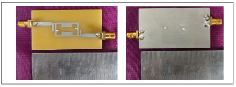
Figure 9: Fabricated design of ASSIR BPF.
VI. RESULTS AND DISCUSSION
The simulated results are obtained using the Advanced Design System Momentum and measured using E5062A network analyzer. The substrate used was FR4 with. The response of the uniform impedance BPF with end coupling is shown in Fig. 10. The filter attains S21 of 0.56 dB, S11 of 46 dB, and a physical size of 0.43g0.19g. The center frequency is fixed at 2.45 GHz, thereby achieving a fractional bandwidth of 8.3%, a roll-off rate of 29%, and transmission zeros at 2.06 GHz and 2.78 GHz.
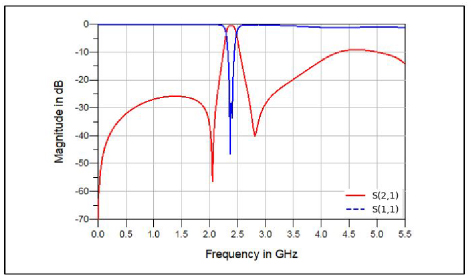
Figure 10: Response of end-coupled UIR BPF.
The calculated and measured response of the stepped impedance resonators with an end-coupled BPF is shown in Fig. 11. From the simulation, the transmission zeros of 2.0 GHz and 3.2 GHz match well with the calculated transmission zeros of 1.94 GHz and 3.23 GHz. Also, both odd and even mode resonances of 2.47 GHz and 5.08 GHz from the simulation are very close to the mathematical results of 2.45 GHz and 5.13 GHz. The physical size of the end-coupling bandpass filter is 0.32g0.22g and a roll-off rate of 41% is noted. First, second, third and fourth spurious signal appear at 5.13 GHz, 7.62 GHz, 9.69 GHz and 12.06 GHz, respectively.
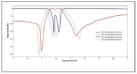
Figure 11: Calculated and simulated response of end-coupled SIR BPF.
Analysis of the stepped impedance resonator BPF with end coupling is as follows. For fixed length L1 of 3 mm, the lengths Lc and L2 are 4.2 mm and 11 mm, respectively, producing a bandwidth of 0.5 GHz and two transmission zeros at 2.2 GHz and 3.67 GHz. The change in lengths of L1 and L2, with a fixed Lc, causes a shift in the transmission zeros to 2.0 GHz and 3.17 GHz. The simulated S21 is 0.71 dB, as observed in Fig. 12. When the feed line is placed at the center of the half-wavelength line with 180∘ tapping, no band is found at f0.
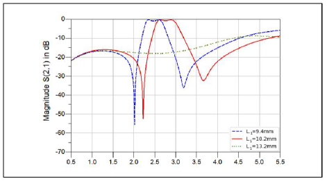
Figure 12: Comparison of end-coupled SIR BPF with various lengths L.
When the coupling width W2 decreases from 3.7 mm to 2.7 mm, a slight shift in center frequency to higher frequencies and a corresponding shift in the transmission zeros are shown in Fig. 13. The change in odd mode (center frequency) and even mode frequencies to higher frequency are also observed. As the coupling gap increases from 0.3 mm to 0.8 mm, the lower and upper transmission zeros move very close to each other. Thus, the bandwidth becomes sharper, focusing the center frequency within the required passband, as noted in Fig. 14.
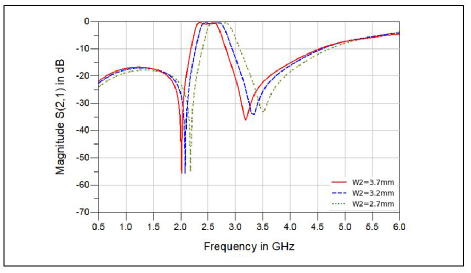
Figure 13: Comparison of end-coupled SIR BPF with various coupling widths W2.
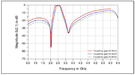
Figure 14: Comparison of end-coupled SIR BPF with various coupling gaps S.
The response of middle-short BPF with end coupling is shown in Fig. 15. The redefined structure improves characteristics such as S21 of 0.36 dB, a size of 0.316g0.186g, and a reasonable roll-off rate of 45 dB/GHz.
As the middle-short resonator behaves like a quarter-wavelength resonator, the first- and second-order spurious signals are shifted to 7.62 GHz and 12.06 GHz, respectively, and therefore the stopband rejection is improved. By adjusting the structure, the required harmonic suppression up to 6 GHz with 20 dB of attenuation and a fractional bandwidth of 29% is achieved.
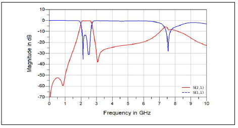
Figure 15: Response of end-coupled MSSIR BPF.
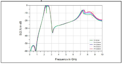
Figure 16: S21 response of MSSIR BPF with short stub position shifted from the center.
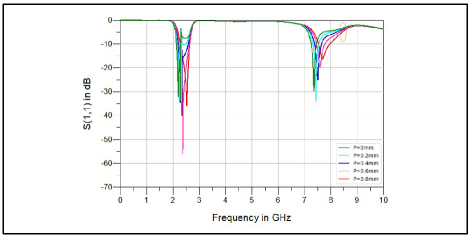
Figure 17: S11 response of MSSIR BPF with short stub position shifted from the center.
However, the introduction of open stubs at the feedlines couples with the folded half-wavelength middle-short-stepped impedance resonator, disrupting the passband bandwidth and reducing insertion loss at the center frequency. Shifting the short stub away from the resonator’s center reduces coupling and therefore effectively preserves the passband bandwidth and enhances insertion loss at the center frequency. Additionally, a very slight unintentional shift in harmonics toward higher frequency is obtained. Thus, various positions (P) of the short stub of the stepped impedance resonator are analyzed without open stubs at the feedlines to understand the behavior of the asymmetric-short resonator-based filter. Improvements in passband bandwidth, insertion loss and unintentional shifts in harmonics are shown in Figs. 16 and 17. As the optimal positioning of the short stub to the resonator is fixed (as shown in Fig. 8), the introduction of open stubs at the feedlines delivers wide stopband attenuation as expected.
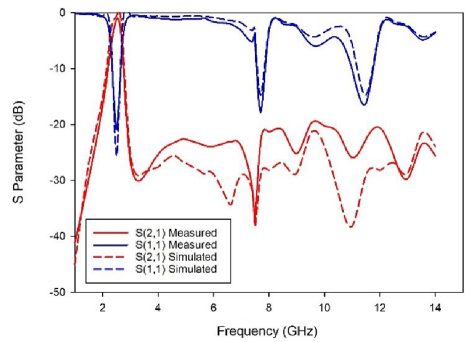
Figure 18: Simulated and measured response of the proposed ASSIR bandpass filter.
The simulated and measured responses of the proposed ASSIR filter with open stubs at the feedlines are shown in Fig. 18. The signal strength in the operating bandwidth and the rejection level in the stopband are essential features in the evaluation of the filter. In the design, asymmetric-short to the resonator with open stubs changes the coupling, which in turn impacts both the resonance condition and the impedance matching at one of the pole frequencies. Therefore, the asymmetric-short resonator-based bandpass filter offers a single reflection pole at the operating frequency of 2.45 GHz. The measured stopband rejection up to 12.8 GHz with 20 dB of attenuation matches the simulated stopband rejection up to 12.8 GHz with 20 dB of attenuation. The S11 of 22.15 dB and the fractional bandwidth of 20.4% also match the simulated S11 of 38.15 dB and the fractional bandwidth of 21.9%. The response shows that both the simulated and measured results satisfy these features and also match closely.
Table 1: Comparison of simulated response of resonators-based filter
| Filter Design | FBW(%) | S21 (dB) | HS* | Size (gg) |
| UIR | 8.3 | 0.56 | 3.5 GHz | 0.430.19 |
| SIR | 20.8 | 0.71 | 3.7 GHz | 0.320.22 |
| MSSIR | 29 | 0.36 | 6 GHz | 0.30.18 |
| ASSIR | 21.9 | 0.35 | 12.8 GHz | 0.30.18 |
∗HS Harmonic suppression with 20 dB attenuation up to the mentioned frequency
Table 2: Comparison of measured responses with other proposed filters
| Ref. | f0 (GHz) | FBW (%) | S(dB) | S11 (dB) | Upper Stopband Rejection (dB) | Size (gg) |
| [9] | 2.4 | 12.1 | 1.2 | 15 | - | 0.037g2 |
| [10] | 2.9 | 24 | 0.7 | 12 | 15 (1.89f0) | 0.20.2 |
| [11] | 2.45 | 10 | 0.79 | 22.7 | - | 0.920.345 |
| [12] | 2.1 | 19 | 1.8 | 12 | 18 (3f0) | 0.390.28 |
| [13] | 1.72 | 16.3 | 0.7 | - | - | 0.050.07 |
| [14] | 2.1 | 39 | 0.8 | 20.6 | 29.5 (2.3f0) | 0.390.36 |
| [15] | 2.5 | 36 | 0.6 | 15 | 42 (2.44f0) | 0.210.18 |
| [16] | 3.24 | 58.3 | 0.6 | 14.2 | - | 0.340.34 |
| [17] | 3 | 60 | 0.8 | 13 | 40 (2.36f0) | 0.670.17 |
| [18] | 12.5 | 47 | 1.1 | 10 | 34 | 1.961.12 |
| [19] | 5.4 | 11.4 | 1.2 | 20 | 30 (3f0) | 0.50.35 |
| [20] | 3.4 | 4.06 | 1.2 | - | 30 (3f0) | 0.420.157 |
| [21] | 5 | 6.6 | 0.9 | - | 30 (4.2f0) | - |
| [23] | 2.1 | 17.1 | 0.93 | 15 | 20 (3.19f0) | 0.05g2 |
| This Work | 2.45 | 20.4 | 1.4 | 22.15 | 20 (4.56f0) | 0.30.18 |
Comparison of simulated design parameters, such as the uniform impedance resonator, stepped impedance resonator, middle-short-stepped impedance resonator and asymmetric-short-stepped impedance resonator with open stubs are recorded in Table 1.
Key parameters such as fractional bandwidth (in percentage), S21 (in dB), harmonic suppression with its attenuation level and size in guided wavelength are listed. A fractional bandwidth improvement of more than 63.45% and a miniaturization improvement of 34% are achieved compared to a UIR BPF. The insertion loss (simulated response) shows an improvement of 41% and the harmonic suppression improves by 72.7% when compared with the UIR BPF.
Table 2 compares the parameters of the proposed filter with those of existing filters from various studies. The comparison highlights the efficiency of the proposed filter by considering fractional bandwidth (%), S(dB), S(dB), upper stopband rejection, and circuit size in guided wavelength. The insertion loss (S21) is reduced to as low as 1.4 dB, and harmonic suppression with an attenuation of 20 dB is extended from 2.8 GHz to 12.8 GHz, achieving a stopband rejection of 4.85 f0. S11 reaches as high as 22.15 dB, and a better fractional bandwidth of 20.4% is achieved. The center frequency is fixed at 2.45 GHz, and the circuit area is reduced to 0.3g0.18g. Therefore, the complete design of ASSIR bandpass filter with stubs offers low insertion loss, compact size, and good harmonic suppression with better attenuation. The simple architecture makes the design attractive and affordable. Performance can be further enhanced by minimizing insertion loss by employing superior substratematerials.
VII. CONCLUSION
A bandpass filter is presented using a novel asymmetric-short applied to the stepped impedance resonator. Transmission zeros and resonance frequency of the bandpass filter with end coupling are analyzed mathematically and verified by simulation as an initial step. Further, bandpass filters with symmetric-short and asymmetric-short configurations applied to the stepped impedance resonator are developed and validated. The added open stubs at the feedlines of the filter extend the stopband to a greater extent. Thus, the filter has the potential to be used in a number of applications where out-of-band rejection in the stopband, excellent signal strength in the passband, compact size, and affordability are essential requirements.
REFERENCES
[1] M. Makimoto and S. Yamashita, “Bandpass filters using parallel coupled stripline stepped impedance resonators,” IEEE Transactions on Microwave Theory and Techniques, vol. MIT-28, no. 12, pp. 1413-1417, Dec. 1980.
[2] M. Sagawa, M. Makimoto, and S. Yamashita, “Geometrical structures and fundamental characteristics of microwave stepped-impedance resonators,” IEEE Transactions on Microwave Theory and Techniques, vol. 45, no. 7, pp. 1078-1085, July 1997.
[3] J. S. Hong and M. J. Lancaster, Microstrip Filters for RF/Microwave Applications. New York: Wiley, 2001.
[4] L.-H. Hsieh and K. Chang, “Tunable microstrip bandpass filters with two transmission zeros,” IEEE Transactions on Microwave Theory and Techniques, vol. 51, no. 2, pp. 520-525, Feb. 2003.
[5] J.-T. Kuo and E. Shih, “Microstrip stepped impedance resonator bandpass filter with an extended optimal rejection bandwidth,” IEEE Transactions on Microwave Theory and Techniques, vol. 51, no. 5, pp. 1554-1559, May 2003.
[6] C.-F. Chen, T.-Y. Huang, and R.-B. Wu, “Design of microstrip bandpass filters with multiorder spurious-mode suppression,” IEEE Transactions on Microwave Theory and Techniques, vol. 53, no. 12, pp. 3788-3793, Dec. 2005.
[7] J.-X. Chen and Q. Xue, “Compact microstrip low-pass filter with suppression of spurious response,” IEE Proceedings-Microwave Antennas Propagation, vol. 153, no. 5, pp. 432-434, Oct. 2006.
[8] C.-X. Sun, L.-Y. Feng, X.-Y. Liu, and H.-X. Zheng, “Compact dual-mode filter using meander shorted stub loaded resonators,” Progress in Electromagnetics Research Letters, vol. 30, pp. 195-203, 2012.
[9] B. Afzali, H. Abbasi, F. Shama, and R. Dehdasht-Heydari, “A microstrip bandpass filter with deep rejection and low insertion loss for application at 2.4 GHz useful wireless frequency,” International Journal of Electronics and Communications (AEU), vol. 138, p. 153811, 2021.
[10] D.-S. La, X. Guan, M.-Y. Wang, and R.-Q. Mi, “Compact wideband bandpass filter based on coupled line stub with high selectivity,” International Journal of Electronics and Communications (AEU), vol. 138, p. 153872, 2021.
[11] S. Chen, L.-F. Shi, G.-X. Liu, and J.-H. Xun, “An alternate circuit for narrow-bandpass elliptic microstrip filter design,” IEEE Microwave and Wireless Components Letters, vol. 27, no. 7, pp. 624-626, July 2017.
[12] K. D. Xu, F. Zhang, Y. Liu, and Q. H. Liu, “Bandpass filter using three pairs of coupled lines with multiple transmission zeros,” IEEE Microwave and Wireless Components Letters, vol. 28, no. 7, pp. 576-578, July 2018.
[13] Q. Xue and J. Y. Jin, “Bandpass filters designed by transmission zero resonator pairs with proximity coupling,” IEEE Transactions on Microwave Theory and Techniques, vol. 65, no. 11, pp. 4103-4110, Nov. 2017.
[14] S. Lu, K.-D. Xu, Y. Guo, Y. Ren, and Q. Chen, “Bandpass filter using coupled line-stub cascaded structure with high stopband rejection,” Microwave Optical Technology Letter, pp. 1-6, Feb.2020.
[15] J. Xu, F. Xiao, Y. Cao, Y. Zhang, and X. Tang, “Compact microstrip filter with third-order quasi-elliptic bandpass response,” IEEE Access, vol. 6, pp. 63375-63381, Nov. 2018.
[16] Q. Yang, M. Shu, C. Guo, J. Li, and A. Zhang, “High selectivity wideband bandpass filter based on stepped impedance open stubs loaded ring resonator,” International Journal of Electronics and Communications (AEU), vol. 126, p. 153408,2020.
[17] P. Vryonides, S. Arain, A. Quddious, D. Psychogiou, and S. Nikolaou. “A new class of high-selectivity bandpass filters with constant bandwidth and 5:1 bandwidth tuning ratio,” IEEE Access, vol. 12, pp. 16489-16497, Feb. 2024.
[18] T. Khorand and M. S. Bayati, “Novel half-mode substrate integrated waveguide bandpass filters using semi-hexagonal resonators,” International Journal of Electronics and Communications (AEU), vol. 95, pp. 52-58, 2018.
[19] S. Ramkumar and R. B. Rani, “Compact high-selective wide-stopband coupled bandpass filter using middle-shorted hairpin-resonators,” International Journal of Electronics and Communications (AEU), vol. 162, p. 154580, 2023.
[20] B. Ren, C. Le, X. Guan, and Z. Ma, “Short-circuited stub-embedded ring resonator and its application in diplexer,” IEEE Access, vol. 7, pp. 179266-179272, 2019.
[21] B. Lee, S. Nam, S.-W. Jeong, and J. Lee, “Post-loaded substrate-integrated waveguide bandpass filter with wide upper stopband and reduced electric field intensity,” IEEE Microwave and Wireless Components Letters, vol. 30, no. 4, pp. 371-374, Apr. 2020.
[22] Z. L. Su, B. W. Xu, S. Y. Zheng, H. W. Liu, and Y. L. Long, “High-isolation and wide-stopband SIW diplexer using mixed electric and magnetic coupling,” IEEE Transactions On Circuits and Systems—II: Express Briefs, vol. 67, no. 1, pp. 32-36, Jan. 2020.
[23] A. Iqbal, J. J. Tiang, S. K. Wong, S. W. Wong, and N. K. Mallat, “QMSIW-based single and triple band bandpass filters,” IEEE Transactions on Circuits and Systems—II: Express Briefs, vol. 68, no. 7, pp. 2443-2447, July 2021.
BIOGRAPHIES

Pritha Narayanan received the M.E. degree in Applied Electronics from Sathyabama Institute of Science and Technology, Chennai, India, in 2013. She received the B.E. degree in ECE from Adhiparasakthi College of Engineering, Anna University. She is working as an Assistant Professor in the Department of Electronics and Communication Engineering at Panimalar Engineering College, specializing in RF and microwave engineering. Her research focuses on developing novel bandpass filter design for microwave and mm wave applications. She has published over 15 peer-reviewed articles in the field of ECE.

Maheswari Shanmugam received the Ph.D. degree in Microwave Engineering and M.E. degree in Applied Electronics from Sathyabama Institute of Science and Technology, Chennai, India, in 2016 and 2009, respectively. She received the B.E. degree in ECE from the University of Madras. Her area of research includes microwave and millimeter wave circuits. She has more than two decades of teaching experience. Currently she is working as a Professor in Panimalar Engineering College, Chennai. She is a recognized supervisor for doing research in Anna University. She has published more than 30 papers in Web of science, Scopus indexed journals and IEEE conferences. She is a Fellow of IETE.
ACES JOURNAL, Vol. 40, No. 7, 617–626
doi: 10.13052/2024.ACES.J.400706
© 2025 River Publishers