Crosstalk Analysis of Multi-conductor Transmission Lines Excited by Long-time Interference Sources Based on Finite-differenceFrequency-domain Method
Zhihong Ye, Yufan Zhai, and Meilin Liu
1Chongqing Institute of Digital Arena
Chongqing 400065, China
yezh@cqupt.edu.cn
2School of Communication and Information Engineering
Chongqing University of Posts and Telecommunications
Chongqing 400065, China
zhai997497548@163.com
3School of Aeronautics and Astronautics
Shanghai Jiao Tong University, Shanghai, China
meilin.liu@sjtu.edu.cn
Submitted On: February 8, 2025; Accepted On: June 28, 2025
ABSTRACT
When addressing the crosstalk problems of multi-conductor transmission lines (MTLs) excited by long-time interference sources, time-domain methods suffer from lengthy simulation duration for such scenario, while the conventional finite-difference frequency-domain (FDFD) method encounters efficiency limitations due to its requirement for direct meshing the fine structures of MTLs. Under the circumstance, a new frequency-domain hybrid method based on the FDFD method and the transmission line (TL) equations is proposed. Within this method, the crosstalk model of the MTLs is constructed depending on TL equations firstly. Then, TL equations are solved by the difference scheme of FDFD method, and the FDFD-TL matrix equation applicable for the crosstalk modeling of MTLs are derived and established. Finally, the conjugate gradient method combined with message passing interface (MPI) parallel technique is utilized to solve the FDFD-TL matrix equation and obtain the voltage responses along the MTLs and their terminal loads. Two simulation cases about the crosstalk of multi-conductor TLs excited by lumped pulse sources are calculated and compared with the Method of Moments (MoM) to verify the accuracy and efficiency of the proposed method.
Index Terms: Crosstalk of multi-conductor transmission lines, FDFD-TL matrix equation, long-time interference sources, message passing interface-based conjugate gradient method.
I. INTRODUCTION
With the rapid advancement of wireless communication technology, electronic and electrical devices are becoming increasingly integrated. The compact arrangement of transmission lines (TL) in these devices can lead to crosstalk, primarily due to inductive and capacitive coupling between neighboring lines. Additionally, the interference sources in these devices generated from some circuit modules may be some harmonic or narrow band signals, which have the prominent feature of long duration. Therefore, studying the crosstalk issues arising from multi-conductor transmission lines (MTLs) subjected to long-time interference sources is essential for developing techniques to mitigate interference in electronic and electrical devices.
Limited to the fine structures of MTLs and long duration of interference sources, full-wave algorithms, such as finite-difference time-domain (FDTD) [1] method, finite element method (FEM) [2], Method of Moments (MoM) [3], transmission line matrix (TLM) method [4], and finite-difference frequency-domain (FDFD) method [5], are not efficient for this crosstalk simulation issue because they require many grids and demand relatively long computation time.
Some hybrid methods based on the theory of TL equations have been proposed, offering the advantage of avoiding direct modeling of TL structures. Among these methods, the FDTD and finite-element time-domain (FETD) solutions of TL equations [6–14] are the most widely used. The core concept of the FDTD solutions of TL equations is to discretize TL equations using different FDTD schemes, such as traditional FDTD [6, 7], alternating direction implicit FDTD [8], Hermite polynomial FDTD [9], and Implicit-Wendroff FDTD [10], then the iteration formulas of the voltages and currents along various TLs are obtained to solve the voltage and current responses of these lines iteratively. Additionally, some researchers have integrated the FDTD solutions of TL equations with machine learning to predict the crosstalk of twisted-wire pairs [11] and random harness cables [12]. Although the FETD-TL method [13, 14] offers advantages over FDTD-TL approaches through its unconditional convergence and freedom from Courant-Friedrich-Levy (CFL) stability constraints, its implementation requires substantial theoretical derivation for establishing the solving equations. Since these methods rely on FDTD and FETD, they often require significant computation time when dealing with interference signals that have longer duration or narrow frequency bands.
The BLT equation [15, 16] and modal analysis method [17] are well-established frequency-domain methods suitable for the crosstalk of the MTLs, which can circumvent the relatively long-time calculations of time domain methods. It is characterized by constructing the relationship equations between the interference source and the voltage or current responses at the terminal loads of the MTLs through the scattering and transmission matrices and then solving the equations to obtain the terminal loads’ voltage or current responses via matrix operations. While the BLT equation can only obtain the voltage or current responses of terminal loads, the secondary radiation of the MTLs cannot be carried out.
The core idea of the modal analysis method [17] is to decouple multi-conductor TL equations into independent modal voltage and current equations by diagonalizing the per-unit-length impedance and admittance matrices using complex transformation matrices and then establish and solve the compact matrix formulations relating to the end voltages and currents. However, it requires solving eigenvalue equations to determine the transformation matrix elements for each frequency point, which requires a lot of theoretical derivation. Additionally, the cross-sectional line dimensions and surrounding media properties in this method should be invariant along the MTLs.
Therefore, a new solution of TL equations based on the FDFD method is proposed in this paper, which can realize the fast crosstalk simulation of multi-conductor TLs excited by long-time interference sources and obtain the voltage and current responses along the MTLs.
II. FDFD SOLUTION FOR THE CROSSTALK OF MULTI-CONDUCTOR TRANSMISSION LINES
Generally, the MTLs are close to the grounding plate, and the material of MTLs is seen as perfect conductor (PEC), on the basis that the electric fields surrounding the MTLs are approximated as quasi-TEM modes. Subsequently, the crosstalk of MTLs can be modeled using frequency-domain TL equations to avoid direct meshing the MTL structures, which can be expressed as
| (1) | |
| (2) |
where l stands for the arbitrary direction of the MTLs. and denote the current and voltage vectors on the MTLs, respectively. R, L, G, and C are the per unit length resistance, inductance, conductance, and capacitance matrices of the MTLs, respectively, which can be calculated by the empirical formulas from [17].
The MTLs are divided into N segments according to the FDFD grid l, as shown in Fig. 1, where the voltages and currents on the MTLs are sampled alternately, with voltages located at integer grid nodes and currents at half grid nodes. Crucially, the FDFD method requires grid resolutions satisfying the CFL condition [17], with spatial discretization constrained to below one-tenth wavelength of the interference source for stable computations.
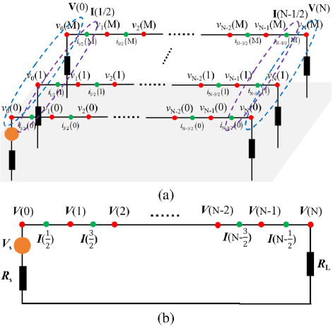
Figure 1: FDFD difference scheme of multi-conductor transmission lines. (a) 3D view of FDFD grid of MTLs and (b) 2D view of FDFD grid of MTLs.
Discretizing equations (1) and (2) by the difference scheme of FDFD, respectively, yields
| (3) |
| (4) |
From equation (4), it follows that
| (5) |
| (6) |
Substituting equations (5) and (6) into equation (3), we get
| (7) |
Further arranging equation (7) as
| (8) |
Due to the ends of TLs being terminated by lumped sources and resistance loads, as shown in Fig. 1, the voltages at both terminal ports of the MTLs do not satisfy the center difference scheme of FDFD. Thus, they should be solved using forward and backward difference schemes [18] to establish the boundaries.
To determine the starting port’s voltages, forward difference scheme is applied to discretize equation (1) as
| (9) |
According to Ohm’s law, the voltages and currents at the starting port satisfy the condition as
| (10) |
Equation (10) can be further arranged to get the expression of the load’s current as
| (11) |
According to equation (5), the current term in equation (9) can be written as
| (12) |
Substituting equations (11) and (12) into equation (9), which is further arranged as
| (13) |
Rewriting equation (13) as
| (14) |
Similarly, the backward difference scheme is used to discretize equation (1) for solving the voltages on the ending port, which is expressed as
| (15) |
The voltage and current at the ending load also comply with Ohm’s law, which can be expressed as
| (16) |
Similarly, the current term in equation (15) can be derived using equation (5), which is expressed as
| (17) |
Substituting equations (16) and (17) into equation (15), which is further arranged as
| (18) |
Rewriting equation (18) as
| (19) |
To solve the voltages along the MTLs, equations (8), (14) and (19) are combined to construct the FDFD-TL matrix equation, which is expressed as
| (27) | |
| (46) |
where the coefficient matrix is represented as A, and its elements are denoted as
| (21a) | |
| (21b) | |
| (21c) | |
| (21d) |
The voltage vector is defined as V, expressed as , where
The excitation source vector is defined as b, expressed as , where
| (30) |
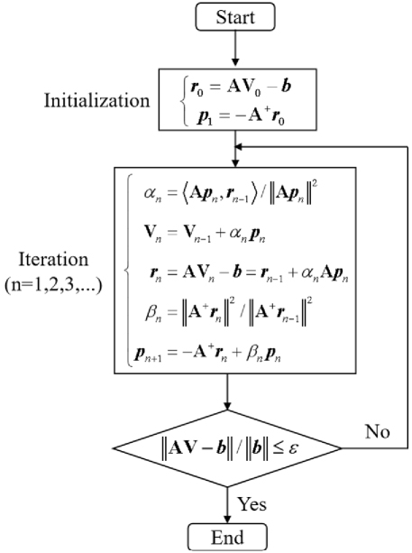
Figure 2: Flow chart of conjugate gradient method.
The coefficient matrix A is a complex sparse matrix with many zero elements. To minimize memory usage, an efficient triple storage format of sparse matrix [19] is employed to store the non-zero elements of A along with their corresponding row and column indices. Considering the non-zero elements in this sparse matrix exhibit no symmetric distribution, the conjugate gradient method [20] is preferred to solve the FDFD-TL matrix equation efficiently. Its detailed procedure is shown in Fig. 2, where n stands for the n-th iteration step and is the maximum error value.
Additionally, when the MTL lengths are sufficiently long, a large number of FDFD grids will be required. This can significantly increase the size of the coefficient matrix, reducing the iteration efficiency of the conjugate gradient method. To address this issue, the message passing interface (MPI) parallel technique [21] is introduced to facilitate the parallel computation of the FDFD-TL matrix equation via multiple threads. The MPI parallel strategy is to distribute the matrix operation tasks by the main process to multiple sub-processes. The partial solutions from each sub-process are then aggregated to the main process to obtain the voltages at all nodes of the MTLs. This enhancement can notably improve the crosstalk simulation efficiency of MTLs.
Currently, the responses along the MTLs can be calculated using equation (5), once the voltages on the MTLs are obtained.
III. NUMERICAL SIMULATION
To assess the accuracy and efficiency of the proposed method, two typical simulation cases about the crosstalk of MTLs on perfect conductor (PEC) plane excited by lumped voltage pulse sources are employed to be solved by the proposed method and full-wave MoM and then comparing their results in terms of precision and computation time.
Figure 3 illustrates the crosstalk model of two TLs on the PEC plane, where the length, radius, height, and distance of the lines are 1 m, 1 mm, 1 cm, and 1 cm, respectively. The starting port of TL #1 is excited by a Gaussian pulse voltage source, denoted as U, and expressed as , where amplitude A 1 V, pulse width 2 ns, and time delay 1.6 ns. This voltage source has an inner impedance of Z 50. The other terminals of both lines are connected to resistance loads, also of 50. The model parameters are listed in Table 1.
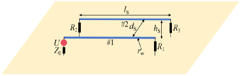
Figure 3: Crosstalk model of two parallel transmission lines on the PEC plane.
Table 1: Model parameters of first case
| Parameter | Value |
| Length ls | 1 m |
| Radius rw | 1 mm |
| Height hs | 1 cm |
| Distance ds | 1 cm |
| Voltage source U | A 1 V, 2 ns, 1.6 ns |
| Inner impedance Z0 | 50 |
| Loads R1R3 | 50 |
The proposed method was implemented on a computing node equipped with an Intel Xeon 2.4 GHz, 32-core processor and 64 GB RAM, utilizing MPI 3.2 with 8-thread parallelization for execution. The discrete grid size selected by the FDFD is l /30 1 cm, where stands for the minimum wavelength of Gaussian pulse. Within the MoM, the lines are divided into line segments according to the same grid size of FDFD, requiring a total of 200 segments. Meanwhile, the PEC plane is represented by half space Green’s function. Additionally, the sampling frequency number of the proposed method and MoM are both 200 with interval of 5 MHz.
The real and imaginary parts of the voltage responses on loads R1 and R3 obtained using the proposed method and MoM, are shown in Figs. 4 and 5. It can be seen that the results of the two methods are in good agreement.
To quantitatively evaluate the proposed method, the relative errors (REs) of the results obtained by the two methods are calculated, with the maximum RE being only 3.8%. Here, RE is defined as
| (31) |
where i stands for the i-th sampling frequency, FN is the sampling frequency number. and are the real parts or imaginary parts of the voltage responses at i-th sampling frequency obtained by the proposed method and MoM, respectively.
Furthermore, the computation times required by the proposed method and MoM are 1.2 s and 21.8 s, respectively, demonstrating the high computational efficiency of this method.
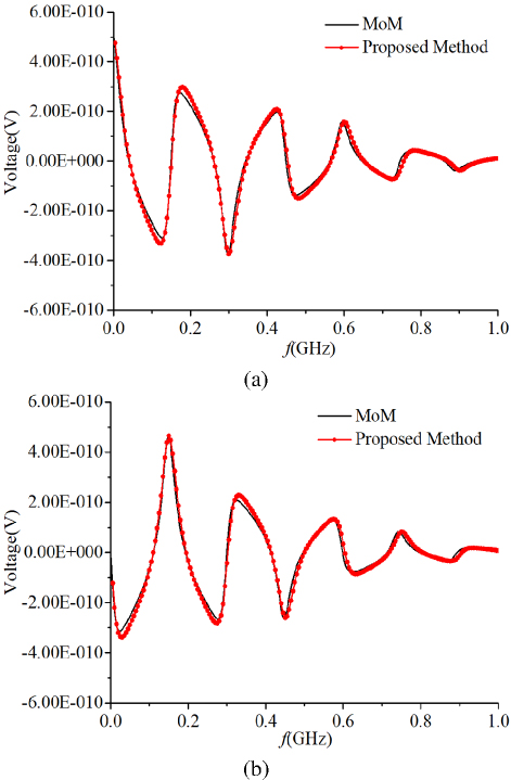
Figure 4: Voltage responses on the load R1 obtained by the two methods for the first case. (a) real parts of the voltages and (b) imaginary parts of the voltages.
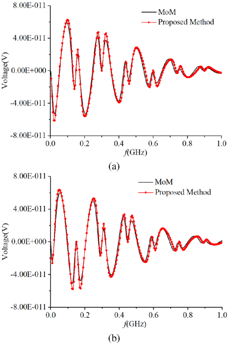
Figure 5: Voltage responses on the load R3 obtained by the two methods for the first case. (a) real parts of the voltages and (b) imaginary parts of the voltages.
To establish a rigorous validation framework, the proposed method is benchmarked against MoM and FDTD-TL method through crosstalk simulation of MTLs excited by prolonged LEMP waveforms.
Figure 6 is the crosstalk model of four TLs on the PEC plane excited by a LEMP voltage source with inner impedance of 50, where the length, radius, and height of the four lines are 100 m, 1 mm, and 10 cm, respectively. Distance between adjacent lines is 5 cm. Terminal loads of the MTLs are also 50. The starting port of TL #2 is excited by the LEMP voltage source, expressed as , where A 51946 V, 1.1105s-1, 1.1105s-1 [22]. The model parameters are all listed in Table 2.
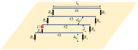
Figure 6: Crosstalk model of four parallel transmission lines excited by LEMP voltage source.
Table 2: Model parameters of second case
| Parameter | Value |
| Length ls | 100 m |
| Radius rw | 1 mm |
| Height hs | 10 cm |
| Distance ds | 5 cm |
| Voltage source U | A 51946 V, 1.1105s-1, 1.1105s-1 |
| Inner impedance Z0 | 50 |
| Loads R1R7 | 50 |
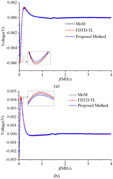
Figure 7: Voltage responses on the load R5 obtained by the two methods for the second case: (a) real parts of the voltages and (b) imaginary parts of the voltages.
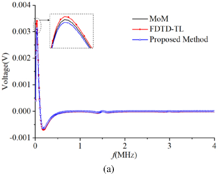
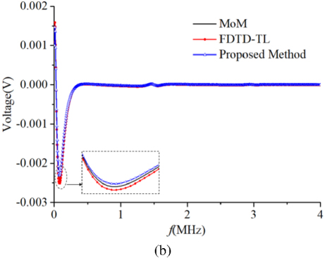
Figure 8: Voltage responses on the load R6 obtained by the two methods for the second case: (a) real parts of the voltages and (b) imaginary parts of the voltages.
The grid size selected by the proposed method is 1 m, which is also determined by the CFL condition. Similarly, each line of the MTLs in MoM is meshed by FDFD grid, yielding 400 line segments. The ground plane is also model by half space Green’s function. Additionally, the sampling frequency number of the proposed method and MoM are both 400 with interval of 10 kHz. Within the FDTD-TL method, the time domain TL equations transforming from equations (1) and (2) are discretized by the space step of 1 m and time step of 1.667 ns to iteratively calculate the current and voltage responses along the MTLs. To ensure the spectral accuracy in the Fourier transform analysis of MTL voltages or currents, the FDTD-TL simulation requires a total duration spanning multiple LEMP cycles. Considering the waveform persistence of LEMP reaching 100 s, 120,000 time steps are used for this method.
The voltage responses on the loads R5 and R6 are calculated by the three methods and the results are compared in Figs. 7 and 8. The results of these methods align closely and the maximum RE values of our method and FDTD-TL method with MoM are approximately 4.0% and 4.6%, respectively. Additionally, the computation time for MoM is 49.8 s, the FDTD-TL method requires 96 s, while the proposed method needs 4.4 s.
IV. CONCLUSION
To enhance the efficiency of crosstalk simulations for multi-conductor transmission lines (MTLs) affected by long-duration interference sources, we propose a new frequency-domain hybrid method that combines the finite-difference frequency-domain (FDFD) method with TL equations. The innovative aspect of this approach is the derivation and establishment of the FDFD-TL matrix equation, which is specifically designed for the crosstalk modeling of MTLs excited by long-time interference sources. Meanwhile, the voltage responses along the MTLs are efficiently solved using the MPI-based conjugate gradient method. Crosstalk simulations of MTLs containing two lines or four lines are completed by the proposed method and MoM, and the accuracy and efficiency of this method have been validated through comparisons of their results concerning precision and time consumption. Currently, the proposed method does not account for the frequency-dependent properties of MTLs and assumes the MTLs in straight configuration. Future research will focus on addressing these limitations to improve the method’s applicability.
ACKNOWLEDGMENT
This work was supported by the Special Support for Chongqing Postdoctoral Research Project (Grant No. 2022CQBSHTB3018).
REFERENCES
[1] Z. R. Gao, H. C. Zhao, L. Yang, and F. S. Wang, “Numerical simulation of the coupling of ultra-wide band electromagnetic pulse into landmine by aperture,” Chin. Phys. B, vol. 24, no. 9, p. 094101, July 2015.
[2] K. H. Fan, B. Wei, X. B. He, Y. W. Li, and X. L. Wei, “A hybrid FETD algorithm for electromagnetic modeling of fine structures,” IEEE Antennas Wireless Propag. Lett., vol. 18, no. 12, pp. 2771-2775, Dec. 2019.
[3] M. Azadifar, P. Dehkhoda, S. H. H. Sadeghi, and R. Moini, “A hybrid FDFD-MoM technique for susceptibility evaluation of a transmission line inside a perforated enclosure,” IEEE Trans. Electromagn. Compat., vol. 56, no. 6, pp. 1474-1479, Dec.2014.
[4] D. Y. Zhou, H. J. Zhou, Z. H. Ye, Q. Feng, and C. Liao, “Transient response of transmission lines with lumped circuit termination based on the TLM,” in 5th IEEE International Symposium on Microwave, Antenna, Propagation and EMC Technologies for Wireless Communications, Chengdu, China, 2013.
[5] K. Masumnia-Bisheh, K. Forooraghi, and M. Ghaffari-Miab, “Electromagnetic uncertainty analysis using stochastic FDFD method,” IEEE Trans. Antennas Propag., vol. 67, no. 5, pp. 3268-3277, May 2019.
[6] Y. X. Sun, Q. Li, W. H. Yu, Q. H. Jiang, and Q. K. Zhuo, “Study on crosstalk between space transient interference microstrip lines using finite difference time domain method,” Applied Computational Electromagnetics Society (ACES) Journal, vol. 30, no. 8, pp. 891-896, Aug. 2015.
[7] Z. H. Ye, M. Z. Ru, and X. L. Wu, “Crosstalk analysis of printed circuit board traces with right-angled bent corners via time domain hybrid method,” IEEE Trans. Electromagn. Compat., vol. 64, no. 6, pp. 2227-2237, Dec. 2022.
[8] Z. Y. Huang, L. H. Shi, B. Chen, and Y. H. Zhou, “A new unconditionally stable scheme for FDTD method using associated Hermite orthogonal functions,” IEEE Trans. Antennas Propag., vol. 62, no. 9, pp. 4804-4809, Sep. 2014.
[9] J. Y. Wang, T. Jiang, R. F. Sun, and Y. X. Sun, “Time domain solutions of transmission line crosstalk,” in IEEE International Symposium on Antennas and Propagation, Denver, CO, USA, 2022.
[10] W. Zhang, Z. Chen, J. F. Ding, and Y. J. Wu, “Grounding characteristics of shielded wire crosstalk at high frequency,” in Asia-Pacific International Symposium on Electromagnetic Compatibility (APEMC), Beijing, China, 2022.
[11] B. M. Xiao, J. M. Zhou, X. F. Liu, W. Yan, Y. Cao, and Y. Zhao, “Crosstalk prediction in twisted-wire pairs based on beetle swarm optimization algorithm,” IEEE Access, vol. 9, pp. 84588-84595, June 2021.
[12] C. Huang, Y. Zhao, W. Yan, Q. Q. Liu, and J. M. Zhou, “A new method for predicting crosstalk of random cable bundle based on BAS-BP neural network algorithm,” IEEE Access, vol. 8, pp. 20224-20232, Jan. 2020.
[13] X. Liu, X. Cui, and L. Qi, “Time-domain finite-element method for the transient response of multiconductor transmission lines excited by an electromagnetic field,” IEEE Trans. Electromagn. Compat., vol. 53, no. 2, pp. 462-474, 2011.
[14] L. Qi, S. H. Bai, and Q. Shuai, “Finite-element time-domain method for multiconductor transmission lines based on the second-order wave equation,” IEEE Trans. Electromagn. Compat., vol. 56, no. 5, pp. 1218-1227, 2014.
[15] J. K. Du, S. M. Hwang, J. W. Ahn, and J. G. Yook, “Analysis of coupling effects to PCBs inside waveguide using the modified BLT equation and full-wave analysis,” IEEE Trans. Microw. Theory Techn., vol. 61, no. 10, pp. 3514-3523, Oct.2013.
[16] G. Y. Ni, L. Yan, and N. C. Yuan, “Time-domain analytic solutions of two-wire transmission line excited by a plane-wave field,” Chin. Phys. B, vol. 17, no. 10, pp. 3629-3634, Oct. 2008.
[17] C. R. Paul, Analysis of Multiconductor Transmission Lines, 2nd ed. Hoboken, NJ: Wiley, 2008.
[18] Z. H. Ye, X. Z. Xiong, C. Liao, and Y. Li, “A hybrid method for electromagnetic coupling problems of transmission lines in cavity based on FDTD method and transmission line equation,” Progress in Electromagnetics Research M, vol. 42, pp. 85-93,2015.
[19] N. Neuss, “A new sparse-matrix storage method for adaptively solving large systems of reaction-diffusion-transport equations,” Computing, vol. 68, no. 1, pp. 19-36, Sep. 2001.
[20] K. Nayanthara, S. M. Rao, and T. K. Sarkar, “Analysis of two-dimensional conducting and dielectric bodies utilizing the conjugate gradient method,” IEEE Trans. Antennas Propag., vol. 35, no. 4, pp. 451-453, Apr. 1987.
[21] J. Luo, Z. H. Ye, and C. Liao, “An MPI-based parallel FDTD-TL method for the EMI analysis of transmission lines in cavity excited by ambient wave,” IEEE Trans. Electromagn. Compat., vol. 62, no. 1, pp. 212-217, Feb. 2020.
[22] Z. H. Ye, Y. C. Shi, Z. W. Gao, and X. L. Wu, “Time domain hybrid method for the coupling analysis of power line network with curved and multidirectional segments,” IEEE Trans. Electromagn. Compat., vol. 65, no. 1, pp. 216-224, Feb. 2023.
BIOGRAPHIES

Zhihong Ye was born in Taixing, Jiangsu Province, China, on 12 March 1988. He received the B.S. and the Ph.D. degrees from Southwest Jiaotong University in 2010 and 2016, respectively. He became an assistant professor at Chongqing University of Posts and Telecommunications in 2018. His research interests include electromagnetic compatibility, electromagnetic protection, and electromagnetic propagation.

Yufan Zhai was born in Jiyuan, Henan Province, China, in 2001. He is studying for the M.Sc. degree in Information and Communication Engineering from Chongqing University of Posts and Telecommunications. His research interests include computational electromagnetics, electromagnetic compatibility.

Meilin Liu was born in China. He received the B.S. degree in Mechanical and Electronical Engineering from Nanchang College, Nanchang, China, in 2000, the M.S. degree in Biophysics from Nanjing Agricultural University, Nanjing, in 2006, and the Ph.D. degree in Communication and Information System from Nanjing University of Aeronautics and Astronautics, Nanjing, in 2011. He spent two years in King Abdullah University of Science and Technology, Saudi Arabia, as a postdoc researcher. He worked for Shanghai Institute of Satellite Engineering 2013-2019 as a research scientist. He joined Shanghai Jiao Tong University in August 2019. His research interests include various numerical methods for electromagnetic phenomenon simulation and developing novel electromagnetic applications.
ACES JOURNAL, Vol. 40, No. 7, 601–608
doi: 10.13052/2024.ACES.J.400704
© 2025 River Publishers