Use of Plasma in Developing Stealth Technology
Surendra Singh
Department of Electrical & Computer Engineering The University of Tulsa, Tulsa, OK 74104, USA
surendra-singh@utulsa.edu
Submitted On: February 14, 2025; Accepted On: December 28, 2025
ABSTRACT
The objective of this work is to study the scattering characteristics of multiple coatings of plasma coated cylinders and spheres. Both dielectric and conducting cases are considered. The dielectric constant or the refractive index of plasma has a significant impact on the radar cross-section (RCS) of the geometries under study. Using experimentally reported plasma dielectric constants obtained from collision frequency and plasma frequency, we observed that in some cases, depending on the choice of parameters, we see reduction of RCS whereas in others the RCS is enhanced. As a result, designers need to apply plasma with care when it is used as an absorber for RCS reduction. The results of this work are expected to be applicable to the development of plasma stealth technology, which has gained a lot of interest lately.
Keywords: Plasma, radar cross-section, scattering, stealth technology.
1 INTRODUCTION
During the past few years, the use of plasma to reduce the radar cross-section (RCS) of airborne platforms has received considerable attention. The concept of using plasma as an absorber of electromagnetic energy was noted in a report by Musal [1] who observed a drastic reduction of RCS of a body when it is surrounded by a plasma sheath having specific spatial and electromagnetic properties. A similar observation is noted by a number of researchers who have reported communication “blackout” when a spacecraft re-enters the earth’s atmosphere [2]. It is noted that, during the space vehicle’s re-entry, it is enveloped in a “plasma sheath” or “plasma plume” that blocks RF communication. Depending on the frequency of the signal, the plasma sheath either reflects or severely attenuates the reception or transmission of signals that results in communication blackout. This led to the observation that plasma is able to cause disruption in communication as well as make the airborne platform invisible to radar due to reduced RCS. It is well known that the RCS is dependent upon the shape as well as the material constituents of a structure. Traditionally, radar absorbing materials (RAM) have been used to absorb incoming radar energy but this concept works only for certain frequencies and angles of incidence. The maintenance of RAM coated structures is also very expensive due to the nature of coatings. For this reason, it appears that a plasma stealth may be a technology that can provide considerable advantages over RAM coatings in reducing RCS.
Collisional and unmagnetized plasma has a complex dielectric constant. As a result, it can be used as a good absorber of EM waves over a wide range of frequencies. Vidmar [3] noted that plasma generated in air or helium at atmospheric pressure acts as a broadband absorber from VHF to X-band. Chaudhury and Chaturvedi [4, 5] reported on the RCS of a flat plate covered with cold collisional plasma using the finite difference time domain (FDTD) method. Yuan and co-workers [6] reported that a multilayered radar-absorbing structure coated with plasma/RAM reduced the power of the incident wave over a wide frequency band. FDTD in conjunction with Z-transform was utilized to study the RCS of a perfectly conducting (PEC) cylinder covered with unmagnetized plasma [7]. Several researchers have considered scattering of a plane wave by an anisotropic plasma coated conducting sphere [8, 9, 10, 11]. However, none of the works consider multiple layers of plasma, which is the primary focus of this work.
The formulation of the scattering mechanism is already known and available in the literature. The main contribution of this paper is to use plasma coating and show that in some instances the plasma coating can enhance scattering whereas in others it can reduce scattering. This results in an impact on RCS, which is the primary focus of study in this work. Moreover, the dielectric constant of plasma is taken from experimentally observed values, which has not been done in previous publications. Hence, the results and the observations presented in this work are significant.
This paper is organized as follows. Plasma parameters are defined in section 2. In section 3, the basic formulations to compute scattering width (SW) or RCS are provided for simple geometries that include a conducting or dielectric cylinder covered with multilayered plasma and a conducting or dielectric sphere covered with multilayered plasma. The numerical results obtained from the formulations are provided in section 4. In section 5, the main conclusions of the work are reported.
2 PLASMA PARAMETERS
Plasma is a collection of free electrically charged particles including negatively charged electrons and positively charged ions resulting in a net neutral charge. Plasma exists at a variety of temperatures, densities and frequencies, and may be derived from a host of gas mixtures. In the following analysis we assume that the electron-neutral collision frequency in the plasma is such that the mean free path between the collisions is much smaller than the Debye length. The dielectric constant, , for collisional and unmagnetized plasma may be written as:
| (1) | ||
| (2) |
is the plasma frequency (hertz), , is the plasma collision frequency (hertz), is the electron density (), is the electron charge (coulomb), is the electron mass (kg), is permittivity of free space, , and is the frequency (hertz) of the incident electromagnetic wave.
3 SCATTERING WIDTH RCS OF MULTILAYERED GEOMETRIES
3.1 Scattering from a conducting (PEC) infinite cylinder covered with a cylindrical dielectric layer
Consider an infinite (in z-direction) conducting cylinder of radius, , covered with a cylindrical dielectric layer (plasma) of radius, , with permeability and permittivity of the dielectric cylinder , as shown in Fig. 1.
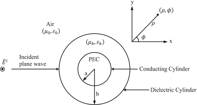
Figure 1 Conducting (PEC) cylinder covered with a plasma layer ().
The incident electric field (), , and the scattered electric field, , in air, for , can be expressed as:
| (3) | |
| (4) |
The electric field in the dielectric (plasma) region, for and , is given by
| (5) |
where and are unknown expansion coefficients, is the wave number in free space, and is the wave number in the dielectric region with and , is permeability of free space, and is permittivity of free space. With the computation of the scattering coefficient, SW can then be computed as [12]:
| (8) |
The above formalism can be extended to any number of layers by defining the fields in each layer and applying the continuity of the tangential electric and magnetic fields at each boundary layer. In this work, we extended the formulation to 5 layers. The case can be handled similarly by defining the z-component of incident magnetic field and applying the appropriate boundary conditions.
Next, consider a dielectric cylinder covered with a cylindrical dielectric layer as shown in Fig. 2.
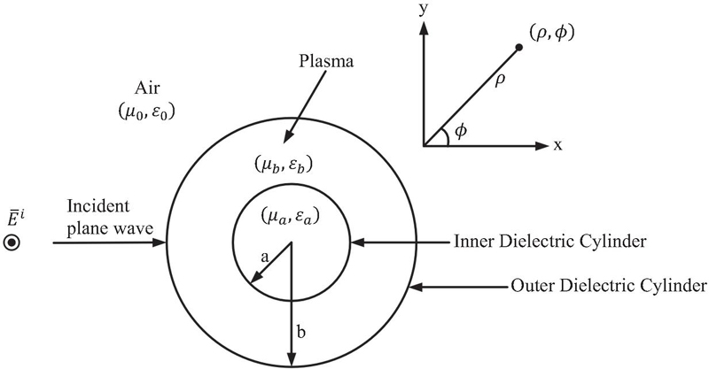
Figure 2 Dielectric cylinder covered with a cylindrical dielectric (plasma) layer ().
Note that the electric field inside the dielectric cylinder for case can be defined as
| (9) |
where is the unknown expansion coefficient, is the wave number of the dielectric material inside the cylinder. RCS can be computed easily using (3.1) once the scattering coefficient is determined by applying appropriate boundary conditions at each dielectric layer. The case for the layered dielectric cylinder is trivial as it can be obtained by application of duality.
3.2 Scattering from a Conducting (PEC) Sphere
Consider a conducting (PEC) sphere of radius, , illuminated by the electric field of a plane wave polarized in the x-direction and propagating along the z-axis as shown in Fig. 3.
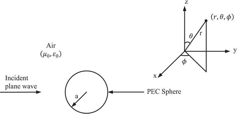
Figure 3 Conducting (PEC) sphere illuminated by a plane wave.
The incident electric field, . Following the development in [12], the incident and scattered fields by the sphere can be expressed as superposition of and fields. The fields are constructed by having and , where is the magnetic vector potential and is the electric vector potential. Similarly, the fields are constructed by having and .
The scattered electric field, and can be computed by using the scattered magnetic vector potential, , and the electric vector potential, . The far field approximations are then made for the scattered fields to arrive at the bistatic RCS of the conducting sphere [12]:
| (10) |
where
| (11) | ||
| (12) |
3.3 Scattering from a conducting (PEC) sphere covered with a spherical dielectric layer
Next, consider the conducting sphere of Fig. 3 covered with a dielectric sphere of radius, , as shown in Fig. 4.
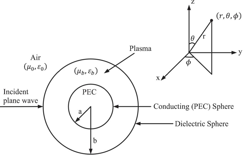
Figure 4 Conducting (PEC) sphere covered with a spherical dielectric layer.
The electric and magnetic fields in the dielectric sphere () can be obtained by defining the vector potentials:
| (13) | |
| (14) |
In (14), is the intrinsic impedance of dielectric medium, . Application of the boundary conditions provides the framework needed to solve for the scattering coefficients, , , , , , and . This formalism can be extended to any number of layers by defining the fields in each spherical layer and applying the continuity of the tangential electric and magnetic fields at each boundary layer. In this work, we extended the formulation to 5 layers. The case of the dielectric sphere covered with a plasma layer, shown in Fig. 5, differs from the stated approach in the boundary condition on the dielectric sphere. That is, we require the continuity of the tangential electric and magnetic fields on the surface of the dielectric sphere at as well. The fields inside the dielectric sphere, , can be determined by defining the potential functions, and :
| (15) | ||
| (16) |
In (16), is the intrinsic impedance of dielectric medium, .
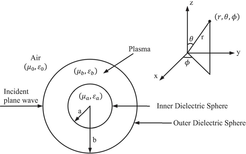
Figure 5 Dielectric sphere covered with a spherical dielectric (plasma) layer.
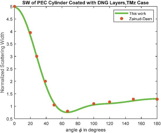
Figure 6 Scattering width of conducting cylinder covered with DNG layer .
4 RESULTS AND DISCUSSION
The formulation for calculating the SW of the cylindrical geometries and the RCS of the spherical geometries were coded in MATLAB. The number of modes in computing the SW in (3.1) and RCS in (11) and (12), is taken to be 50. This number of modes is arrived after numerical experimentation to find the convergence of the series. In this section, the numerical results are presented. First, the codes were tested to compare results with numerical data available in the literature to validate the analytical work presented in section 3 as well as to validate the MATLAB codes. The multilayered (1 to 5 layers) cylinder and sphere codes were first tested for self-consistency. This meant that we set the material properties of the added layers (1 to 5) to that of free space and found the result to match with that of a cylinder or sphere with no layers. In the results to follow, we provide comparison with results that were available in the literature. In each case, we also tested the multilayered formulation in which the extra layers were set to free space. Note that the increasing values of radii of cylinders or spheres (beyond the ones shown in section 3) are denoted by letters c, d, , and f. The bistatic SW of a conducting cylinder coated with a double negative (DNG) coating for and cases for m, m, GHz, , , , shown in Figs. 6 and 7, respectively, are in good agreement with Zainud-Deen’s result [13]. The bistatic RCS of a PEC sphere covered with 2 spherical dielectric layers for E-plane scan is shown in Fig. 8 for GHz. This result is in good agreement with Sheng et al. [14] and it is obtained with the code for a PEC sphere covered with 5 dielectric layers. The PEC sphere radius . The dielectric sphere radii: , , , , , , , , , and for . The quantities in the square parenthesis indicate that these are needed to run the 5-layer case since we only have 2 dielectric layers. For this reason, the relative permeability and relative permittivity of these 3 additional layers are set to free space. The same is true in the next two results where we show the bistatic RCS of a PEC sphere covered with 3 dielectric spherical layers. These results, shown in Fig. 9 for E-plane scan () and in Fig. 10 for H-plane scan (), are in good agreement with Lei [15]. In these two cases, the incident EM wave frequency, GHz and the PEC sphere radius, . Dielectric sphere radii: , , , , , , , , , , and for . Note that the two outermost layers are free space or air.
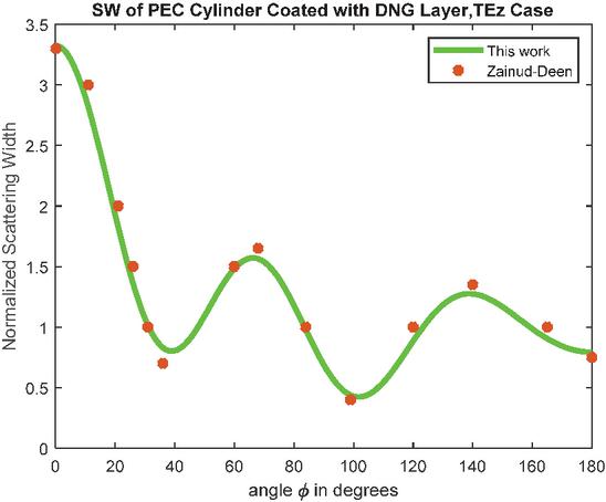
Figure 7 Scattering width of conducting cylinder covered with DNG layer .
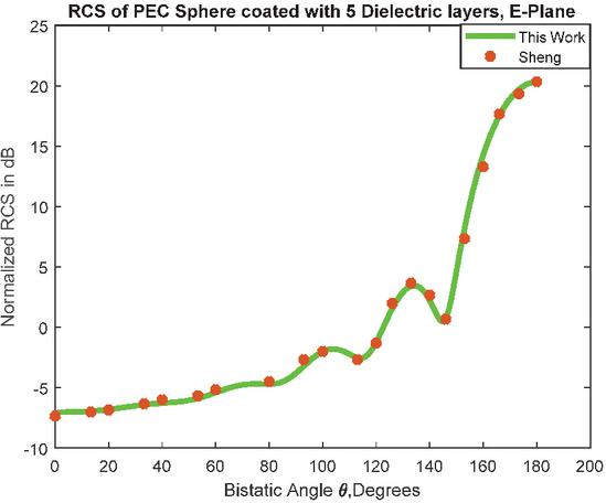
Figure 8 RCS of a PEC sphere covered with 2 dielectric layers E-plane scan.
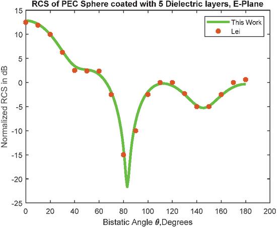
Figure 9 RCS of a PEC sphere covered with 3 dielectric layers E-plane scan.
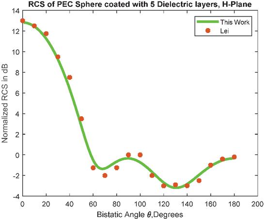
Figure 10 RCS of a PEC sphere covered with 3 dielectric layers H-plane scan.
Next, we look at the impact of the collision frequency on the plasma dielectric constant. The set of results presented in Figs. 11–14 are for frequency of incident EM wave, GHz, , , , , , . In (2), if we take the electron density, , and electron collision frequency, GHz, we obtain the resulting plasma dielectric constant, , and the plasma frequency, GHz. All of the 5 plasma layers are set to have the same dielectric constant, that is, for . In Fig. 11, we show the SW of a dielectric cylinder, case, with and without plasma layers. For this case, the dielectric constant and relative permeability of the dielectric cylinder are given by and , respectively. The SW of a PEC cylinder for the cases with and without plasma layers is shown in Fig. 12. In Fig. 13, we show the bistatic RCS of a dielectric sphere for the E-plane scan () with and without plasma layers. For this case, the dielectric constant and relative permittivity of the dielectric sphere are given by and , respectively. We show the bistatic RCS of a PEC sphere for the H-plane scan with and without plasma layers in Fig. 14. In Figs. 11–14, we observe that when the plasma collision frequency (10 GHz) is higher than the frequency of the incident wave (1 GHz), the scattering is significantly reduced, thereby, making the plasma a lossy material or a good absorber of electromagnetic energy.
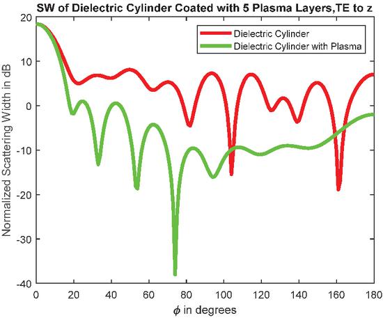
Figure 11 Scattering width of a dielectric cylinder covered with 5 plasma layers .
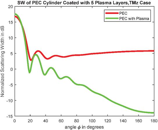
Figure 12 Scattering width of a PEC cylinder covered with 5 plasma layers .
In the next set of results, we look at the impact of reducing the collision frequency below the operating frequency. The results presented in Figs. 17–18 are for frequency of incident EM wave, GHz, , , , , , . Using (2), if we take the electron density, , and electron collision frequency, GHz, we obtain the resulting plasma dielectric constant, , and the plasma frequency, GHz. All of the 5 plasma layers are set to have the same dielectric constant, that is, for . In Fig. 17, we show the SW of a dielectric cylinder, case, with and without plasma layers. For this case, the dielectric constant and relative permeability of the dielectric cylinder are given by and , respectively. We show the SW of a PEC cylinder for the case in Fig. 17 with and without plasma layers. In Fig. 17, we show the bistatic RCS of a dielectric sphere for the E-plane scan () with and without plasma layers. For this case, the dielectric constant and relative permittivity of the dielectric sphere are given by and , respectively. We show the bistatic RCS of a PEC sphere for the H-plane scan in Fig. 18 with and without plasma layers.
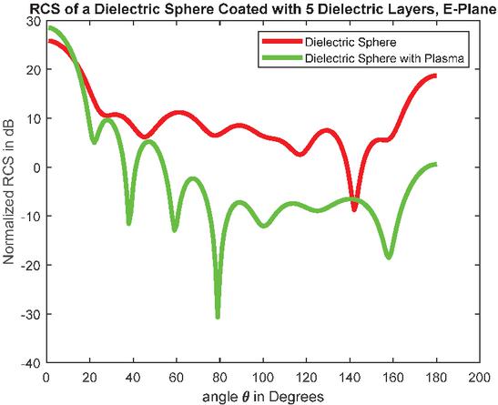
Figure 13 RCS of a dielectric sphere covered with 5 plasma layers E-plane scan.
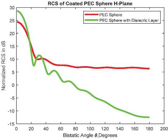
Figure 14 RCS of a PEC sphere covered with 5 plasma layers H-plane scan.
From the results in Figs. 17–18, we make an important observation that when the collision frequency of plasma (0.01 GHz) is much lower than the frequency of the incident wave (1 GHz), the scattering is significantly enhanced to the point where the plasma starts acting as a reflector or partially conducting media.
Even though the plasma layers were all taken to have the same electrical properties, the multi-layered formulation is expected to help in modeling inhomogeneous plasma where each layer may have different electrical characteristics. This is certainly an important and interesting case, the results of which will be reported in the near future.
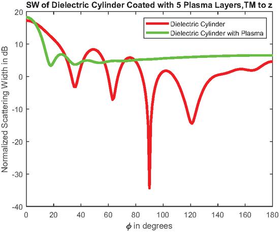
Figure 15 Scattering width of a dielectric cylinder covered with 5 plasma layers .
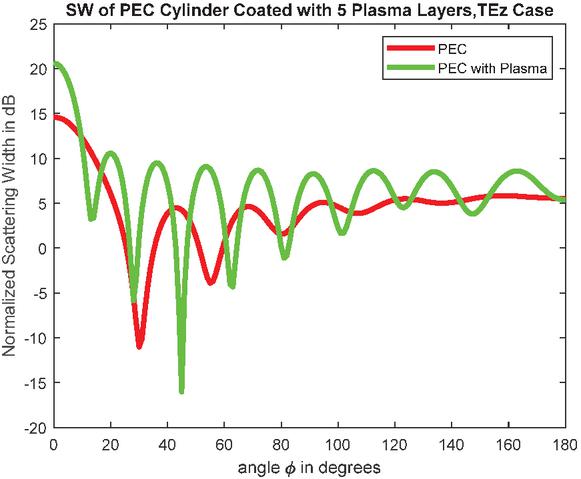
Figure 16 Scattering width of a PEC cylinder covered with 5 plasma layers .
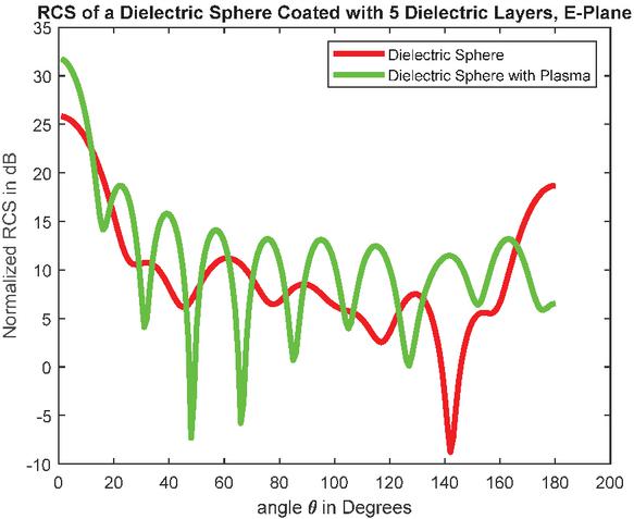
Figure 17 RCS of a dielectric sphere covered with 5 plasma layers E-plane scan.
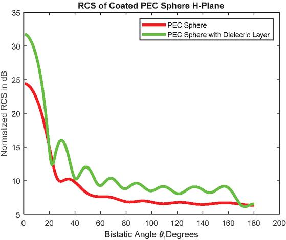
Figure 18 RCS of a PEC sphere covered with 5 plasma layers H-plane scan.
5 CONCLUSION
In this paper, a comprehensive analysis of scattering from conducting and dielectric cylinders coated with multiple layers (up to 5) of plasma and conducting and dielectric spheres coated with multiple layers (up to 5) of plasma is provided. The variation of the SW for the cylindrical case and RCS for the spherical case is provided as a function of angle. It is shown that plasma can act as a reflector or absorber of incoming electromagnetic energy depending on the frequency of the incoming wave and refractive index of the plasma layers. It is noted that electron collision frequency has a significant impact on the dielectric constant of the plasma and consequently on enhancing or reducing the scattering. We make an important observation that when the plasma collision frequency (10 GHz) is higher than the frequency of the incident wave (1 GHz), the scattering is significantly reduced, thereby, making the plasma a lossy material or a good absorber of electromagnetic energy. Moreover, when the collision frequency of plasma (0.01 GHz) is much lower than the frequency of the incident wave (1 GHz), the scattering is significantly enhanced to the point where the plasma starts acting as a reflector or partially conducting media. The results presented here are expected to aid in the study of plasma coatings as a function of the plasma collision frequency in development of stealth technology.
REFERENCES
[1] H. M. Musal, “On the theory of the radar-plasma absorption effect,” GM defense Research Laboratories, Contract NO. DA-04-495-ORD-3567(Z), July 1963.
[2] L. Zheng, Q. Zhao, and X. J. Xing, “Effect of plasma on electromagnetic wave propagation and THz communications for reentry flight,” Applied Computational Electromagnetics Society (ACES) Journal, vol. 30, pp. 1241–1245, Nov. 2015.
[3] R. J. Vidmar, “On the use of atmospheric pressure plasmas as electromagnetic reflectors and absorbers,” IEEE Trans. Plasma Sci., vol. 18, no. 4, pp. 733–741, 1990.
[4] B. Chaudhury and S. Chaturvedi, “Study and optimization of plasma-based radar cross-section reduction using three-dimensional computations,” IEEE Trans. Plasma Sci., vol. 37, no. 11, pp. 2116–2127, 2009.
[5] B. Chaudhury and S. Chaturvedi, “Three-dimensional computation of reduction in radar cross-section using plasma shielding,” IEEE Trans. Plasma Sci., vol. 33, no. 6, pp. 2027–2034, 2005.
[6] C. Yuan, Z. Zhou, J. W. Zhang, X. Xiang, Y. Feng, and H. Sun, “Properties of propagation of electromagnetic wave in multilayer radar- absorbing structure with plasma- and radar-absorbing material,” IEEE Trans. Plasma Sci., vol. 39, no. 9, pp. 1768–1775, 2011.
[7] M. Yan, K. R. Shao, X. W. Hu, Y. Guo, J. Zhu, and J. D. Lavers, “Z-transform based FDTD analysis of perfectly conducting cylinder covered with unmagnetized plasma,” IEEE Trans. Magnetics, vol. 43, no. 6, pp. 2968–2970, June 2007.
[8] Y. Geng, “Scattering of a plane wave by an anisotropic plasma-coated conducting sphere,” Int. J. Antennas and Propagation, vol. 2011.
[9] A. Ghaffar, M. Z. Yaqoob, M. A. S. Alkanhal, M. Sharif, and Q. A. Naqvi, “Electromagnetic scattering from anisotropic plasma-coated perfect electromagnetic conductor cylinders,” Int. J. Electronics and communication (AEU), vol. 68, no. 8, pp. 767–772, 2014.
[10] Z. Rao, G. Zhu, S. He, C. Li, Z. K. Yang, and J. Liu, “Simulation and analysis of electromagnetic scattering from anisotropic plasma-coated electrically large and complex targets,” Remote Sensing, vol. 14, p. 764, 2022.
[11] Y. Geng, “Analysis of electromagnetic scattering by a plasma anisotropic sphere,” Radio Science, vol. 38, no. 6, 2003.
[12] C. A. Balanis, Advanced Engineering Electromagnetics, 2nd ed. Hoboken, NJ: John Wiley & Sons, pp. 610, 655–661, 2012.
[13] S. H. Zainud-Deen, A. Z. Botros, and M.S. Ibrahim, “Scattering from bodies coated with metamaterial using FDTD method,” Prog. Electromagn. Res., vol. 2, pp. 279–290, 2008.
[14] X. Q. Sheng, J. M. Jin, J. Song, C. C. Lu, and W. C. Chew, “On the formulation of hybrid finite element and boundary-integral methods for 3-D scattering,” IEEE Trans. Antennas Propagat., vol. 46, no. 3, pp. 303–311, 1998.
[15] L. Lei, J. Hu, and H.-Q. Hu, “Solving scattering from conducting body coated by thin-layer material by hybrid shell vector element with boundary integral method,” Int. J. Antennas and Propagation, vol. 2012, 2012.
BIOGRAPHY

Surendra Singh is a professor of electrical and computer engineering at The University of Tulsa, USA. He obtained his B.S. degree in electronics and communication engineering from Kurukshetra University, M.Tech. degree in electrical engineering from Indian Institute of Technology, Kanpur, India, and Ph.D. degree in electrical engineering from University of Mississippi, Oxford, MS. He joined the University of Tulsa in 1985 where he teaches electrical engineering and is engaged in computational electromagnetics research. He has participated in over 60 panels at NSF in reviewing for SBIR Phase I and Phase II funding. He actively participates in the Air Force Summer Faculty Fellowship Program.
ACES JOURNAL, Vol. 40, No. 12, 1178–1185
DOI: 10.13052/2025.ACES.J.401205
© 2026 River Publishers