Optimization Design of Active and Passive Hybrid Shielding, for Electric Vehicle’s Wireless Power Transfer System
Yangyun Wu1, Tianhao Wang1, Quanyi Yu1, Gang Lv2, Yaodan Chi3, and Shanshan Guan1
1College of Instrumentation and Electrical Engineering, Jilin University, Changchun 130021, China, wuyy21@mails.jlu.edu.cn, wangtianhao@jlu.edu.cn, qyyu20@mails.jlu.edu.cn, guanshanshan@jlu.edu.cn
2EMC Department National Automotive Quality Supervision and Inspection Center, Changchun 130011, China, lvgang@catc.com.cn
3Jilin Provincial Key Laboratory of Architectural Electricity and Comprehensive Energy Saving, Jilin Jianzhu University, Changchun 130118, China, chiyaodan@jlju.edu.cn
Submitted On: February 19, 2025; Accepted On: January 14, 2026
Abstract
Targeting the issues of electromagnetic exposure safety in the application of an electric vehicle’s wireless power transmission (WPT), this study proposes a surrounding active shield coils structure, laying on the four sides of the WPT system, which effectively reduces the lateral magnetic leakage field while supplementing the magnetic field inside the transmission channel. At the same time, this study proposes a ferrite groove structure as the passive shielding, achieving reduction of the vertical magnetic leakage field. On this basis, the paper takes system transfer efficiency and surrounding magnetic leakage field density as the optimization objectives, combining the extreme learning machine (ELM) surrogate model with multi-objective optimization algorithm for hybrid shielding structural design, realizing the further improvement of power transfer and electromagnetic shielding capability. A numerical simulation test is carried out and the results show that the proposed shielding scheme can ensure the system transfer efficiency, meanwhile reducing the magnetic leakage from all directions, and providing effective electromagnetic exposure safety protection for the human body.
Keywords: Electromagnetic exposure safety, extreme learning machine, hybrid shielding structural design, multi-objective optimization algorithm, wireless power transmission..
1 INTRODUCTION
Developing the electric vehicles industry is an essential strategy for protecting the ecological environment as well as saving fossil energy. In recent years, charging technology has been research hotspot in the field of electric vehicles. With the development of electric vehicles gradually moving towards intelligent networking, the commonly used wired charging station is hardly able to meet the needs of intelligent driving in the future [1, 2]. In contrast, wireless power transmission (WPT) brings convenience and features strong environmental adaptability in its practical application, which makes it a highly suitable charging form for intelligent driving [3, 4]. However, electromagnetic exposure safety issues of the WPT process are gradually emerging as the technology enters the market, which becomes the focus of attention for researchers [5]. To alleviate the electromagnetic fields (EMFs) caused by WPT systems, most existing methods focus on the two categories of active and passive shielding.
Regarding active shielding methods, Cruciani et al. proposed a method to identify the suitable excitation of active coils. The proposed method permits the mitigation of the magnetic leakage in a specific point, the shielding effectiveness (SE) can achieve 20 dB on the considered area with minor losses of efficiency [6]. Cruciani et al. proposed a shielding structure composed of multiple active coils to mitigate the magnetic leakage field of WPT systems, then used a gradient descent algorithm to obtain the most suitable excitation for the active coils. Thus, the magnetic leakage field in the protection area was reduced by nearly half [7]. Mi et al. proposed a double-loop active shield coil directly connected in series with the primary side coil, which reduced the leakage level of the WPT system while eliminating the additional coupling between the shield coil and secondary side coil [8]. Campi et al. proposed a novel design of active coil to reduce the magnetic leakage field generated by the WPT system, which consists of two separate shield coils with independent source. The shielding method was proved to have a minor impact on system transmission performance [9]. Li et al. proposed a double-coil dynamic shielding scheme based on active shielding technology, which adopts two half-loop structures set on the outside of the transmitting side coil, achieving dynamic shielding of EMF leakage while ensuring high transmission efficiency [10].
Passive shielding achieves a reduction of magnetic leakage field mainly by using high permeability ferromagnetic materials or high conductivity metal materials. The method is also widely used in electromagnetic exposure safety protection of WPT systems. Budhia et al. proposed a ferrite shielding composite structure consisting of six parts: plastic cover plate, coupling coil, frame, ferrite magnetic core, aluminum ring, and aluminum backplate, which features satisfactory performance of magnetic leakage shielding [11]. Zhu et al. proposed a shielding method that used aluminum strips applied on the outer side of the transmitting side coils, which reduces the negative impact of eddy current losses on system transmission performance [12]. Mohammad et al. discovered that ferromagnetic materials can effectively suppress the electromagnetic exposure of Double D coil based WPT systems. The experiment result shows that the peripheral magnetic leakage field can be effectively suppressed [13]. Gu et al. proposed combining soft magnetic materials and ferrite as the passive shielding structure of WPT, while retaining the electromagnetic shielding performance. The mechanical stability and thermal conductivity of the shielding structure also improved [14].
Let us now turn to research on hybrid active-passive shielding for WPT systems. Dai et al. proposed the active shielding structure of reverse-wound magnetic shielding coils in series with the main coil, as well as the passive shielding structure based on ferrite, which improved magnetic field distribution around the WPT system [15]. Li et al. proposed a composite electromagnetic shielding structure for WPT, which is composed of Tian-font magnetic shielding and anti-series active coils. The proposed hybrid structure minimizes material use while maintaining safe magnetic leakage levels [16]. Zhang et al. proposed a hybrid shielding system composed of single-source topology-integrated active suppression coils and adjustable ferrites, which generated canceling flux opposite to leakage flux as well as compensation flux consistent with the main flux [17]. Li et al. proposed a hybrid shielding structure consisting of a surrounding coil with a ring-shaped aluminum plate, effectively weakening the magnetic leakage in the edge position of the WPT system [18].
In order to further enhance the overall performance of the WPT system, many scholars conducted research on the application of optimization algorithms for the design of structure of WPT systems. Zhao et al. used a genetic algorithm to optimize metal aluminum shielding structural parameters, reducing the energy losses produced in the aluminum shielding plate of the WPT system [19]. Luo et al. proposed a multi-objective optimization method of a primary side ferrite layer for a Double D coil based WPT system, using the NSGA-II algorithm to optimize the geometrical parameters of ferrite, realizing the improvement of system coupling coefficient and the reduction of stray magnetic leakage fields [20]. Pei et al. proposed a multi-objective optimization method based on particle swarms coupled with the polynomial chaos expansion model to determine the optimal design parameters in the practical shielding design, which increases the system coupling coefficient while also reducing the shielding costs [21].
Compared to the existing literatures, this study effectively combines both active and passive shielding methods, realizing the reduction of the magnetic leakage field in the full place as well as transmission efficiency of the WPT system. This paper skillfully combines extreme learning machine (ELM) neural networks with multi-objective optimization algorithms to improving the overall performance of the WPT system. ELM is used to quickly construct a surrogate model of the optimization variables and objective functions in the shielding structure, and the multi-objective algorithm is used to search for the optimal solution of shielding structural parameters. This paper considers system transfer efficiency as well as the surrounding magnetic leakage flux density as the optimization objective, ultimately improving the overall performance of the WPT system.
The contents of the paper can be expressed as follows. Section 2 introduces the spatial magnetic field distribution of the studied coil type (circular coil), giving the mathematical model of magnetic induction intensity. Section 3 introduces the design idea of hybrid shielding structure and introduces the shielding principle of the proposed active and passive method. Section 4 introduces the proposed optimization method, discussing the overall optimization design process of shielding structure. Section 5 is the specific numerical simulation part, verifying the feasibility of the proposed scheme. Section 6 summarizes the research work of this paper.
2 ANALYSIS OF SPATIAL MAGNETIC FIELD OF WPT
The magnetic energy coil group is the main device for transmitting electricity in the WPT system, which relies on a spatial alternating magnetic field to achieve WPT. Thus, the magnetic energy coil group determines magnetic field distribution in the transmitting channel as well as magnetic leakage field distribution in the surrounding environment to a large extent [22, 23].
The coil groups applied in the WPT system are usually composed of multiple independently insulated twisted wires wound together, which can be divided into the two categories of unipolar coil and bipolar coil according to the mode of magnetic field distribution [24]. The unipolar coil features only single magnetic pole direction, generating the magnetic flux component vertical to the plane of the coil. This type of coil usually features a relatively simple structure, such as circular and rectangular coils [25]. Different from a unipolar coil, the bipolar coil features two directions of magnetic pole, which produces two magnetic flux components that are respectively parallel and vertical to the plane of the coil. This type of coil usually features a complex structure, such as Double D coil or Bipolar coil [26]. The magnetic flux lines of the two types of coil structure are shown as Fig. 1.
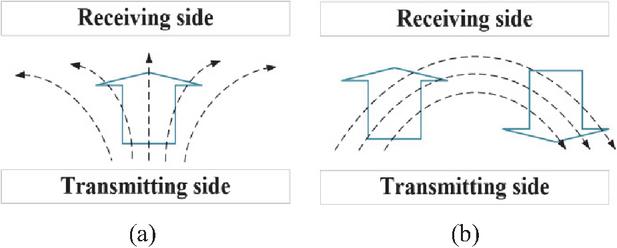
Figure 1 Magnetic flux distributions of different types of coils. (a) Unipolar coil and (b) bipolar coil.
This paper takes the circular coil as the research object. In the Cartesian coordinate system, the total magnetic field density of a certain spatial position can be composed of magnetic flux components in the x, y, z directions. As shown in Fig. 2, assuming that there exists a circular line current I on the plane of XOY, whose radius is R, P(r, , ) is the spherical coordinate value of any point in the spatial domain.
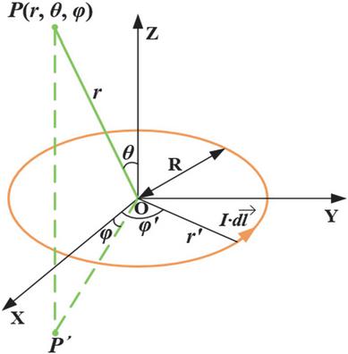
Figure 2 Basic model of circular line current.
Taking the center of the circular line current as coordinate origin, the magnetic vector potential of the circular line current at any spatial point can be expressed as:
| (1) |
where represents vacuum permeability H/m. dl represents the differential line element of the current element , whose spherical coordinate value can be expressed as . According to the relationship between magnetic flux density and magnetic vector potential, the component of the magnetic field density of a circular coil at any point in the Cartesian coordinate system can be calculated as [27]:
| (2) |
In the above equation, p, K, E, and k can be further expressed as:
| (3) | |
| (4) | |
| (5) | |
| (6) |
If we assume that the turns of the transmitting and receiving side coil groups are respectively n and m, the magnetic field generated by each single turn coil at the spatial point P can be expressed as as well as . The magnetic flux density generated by a single-turn coil is the basis for calculating the total field strength:
| (7) |
3 PROPOSED HYBRID SHIELDING FOR MAGNETIC LEAKAGE FIELD MITIGATION
This section proposes a hybrid electromagnetic shielding structure that combines active and passive shielding methods, cutting off the EMF leakage path of the WPT system, while improving the magnetic field distribution in the system transmission region. As shown in Fig. 3, the purpose of the proposed hybrid shielding structure in this paper is to reduce the magnetic flux in regions $\scriptscriptstyle2$⃝ and $\scriptscriptstyle3$⃝, while maintaining the magnetic flux in region $\scriptscriptstyle1$⃝.
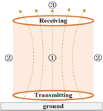
Figure 3 Electromagnetic field distribution diagram of WPT.
3.1 Magnetic guidance of lightweight ferrite
Passive shielding achieves constraint of the magnetic field mainly through using a ferromagnetic or metal material. Ferromagnetic materials can construct a low magnetic resistance path for magnetic flux, to guide the magnetic flux lines to converge towards the transmission channel [28], i.e. region $\scriptscriptstyle1$⃝ in Fig. 3. Calculation of a magnetic path can be solved using Ohm’s law of magnetic paths [29]:
| (8) |
where is magnetic flux volume, F is magnetomotive force, and is resistance of the magnetic path. If we assume that the magnetic circuit interface is uniform, then can be expressed as:
| (9) |
where is magnetic permeability, l is length of magnetic circuit, and S is cross-section area of the magnetic circuit. From Equation (9), the higher the magnetic permeability, the lower the magnetic resistance. The magnetic flux would mainly pass through the path with lower resistance. Thus, priority should be given to using high magnetic permeability materials for shielding. At present, ferrite is widely used for passive shielding of WPT systems, due to its high permeability, high saturation magnetic density, and high resistivity [30].
This paper suggests a novel passive shielding structure based on ferrite materials. The central part is hollowed out to form the groove architecture. The WPT coil groups are embedded inside the ferrite magnetic core in the actual application. The coil groups are enclosed by the ferrite ring, shown in Fig. 4. Compared with an entire ferrite disk, the new structure saves on materials, effectively reducing costs.
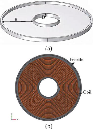
Figure 4 Proposed ferrite groove structure. (a) Basic appearance of the ferrite groove and (b) assembly of the ferrite groove and WPT coils.
In Fig. 4, H is width of the ferrite groove, D is depth of ferrite groove. The special structure facilitates the practical placement of the coil groups. The paper applies the ferrite groove structure to the receiving side of the WPT system, which can concentrate the magnetic in region $\scriptscriptstyle1$⃝ and reduce the magnetic leakage in region $\scriptscriptstyle3$⃝.
3.2 Magnetic flux interaction of the shield coil
The principle of an active shielding method is to use auxiliary coils to generate a reverse magnetic field, thereby offsetting magnetic leakage field at the target position [7]. A traditional active shielding system usually consists of a main coil of WPT and a shield coil, where the current direction of the shield coil is opposite to that of the main coil, thereby forming a magnetic field direction opposite to that of the main coil [31]. Though the magnetic leakage field in the protective area is weakened, the direction of shielding current remains constant, which reduces the transmission efficiency of the WPT system [32, 33].
This study proposes laying the four shield coils on the transmitting side of the WPT system, which all have independent power supply. A top-down perspective is shown in Fig. 5.
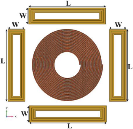
Figure 5 Diagram of the surrounding shield coil.
Here, L and W represent the length and width of the shield coil. By adjusting the power supply of the shield coil, the current of the shield coil is in phase opposition to the current of the WPT transmitting main coil. Adjacent to the main coil, the shield coil can generate a magnetic field in phase with the main coil. Outside the main coil, the shield coil can generate a magnetic field in phase opposition to the main coil.
Taking a cross-section of the WPT system as the observation plane, Fig. 6 represents the magnetic superposition after adding the shield coils. Figure 6 divides the overall area into energy transmission area and magnetic leakage protection area. The lines in Fig. 6 represent the distribution of magnetic flux lines produced by the main coils and the shield coils.
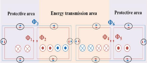
Figure 6 Cross-section diagram of shield coil and main coil.
Assuming that the magnetic flux components generated by the WPT coil are , the magnetic flux components generated by the shield coil on two sides are . It can be seen that the magnetic flux caused by the shield and WPT coil are mutually cancelled out in the outer region, which can effectively weaken the magnetic leakage, while the magnetic flux caused by shield and WPT coil are mutually superimposed in the middle region, which can improve the transmission performance of the WPT system. Magnetic flux in the different regions can be expressed as:
| (10) |
where and represent the total magnetic flux in the middle and outer regions. Combining the initial design idea of electromagnetic shielding structures mentioned in section 3, it can be theoretically concluded that the active coil structure can reduce the magnetic flux in region $\scriptscriptstyle2$⃝ while supplementing the magnetic flux in region $\scriptscriptstyle1$⃝, achieving the dual effect of electromagnetic shielding and transfer performance.
The passive and active shielding structures in this study are made of Mn-Zn ferrite and copper, respectively. The general price range of Mn-Zn ferrite is US$10–30 per kilogram. Due to the lightweight nature of ferrites and the groove shape designed in this study saving on material usage, the cost is not high. The cost of active shielding depends on the volume of copper material, which can be reduced by reducing the number of turns and reducing the wire diameter of the shield coils; the cost range for cheaper copper material is generally US$10–20.
4 MULTI OBJECTIVE OPTIMIZATION SURROGATE MODEL FOR SHIELD STRUCTURE
4.1 Extreme learning surrogate model
In the numerical simulation model of electromagnetic shielding structures there exists a stronger nonlinearity relationship between the shielding structural parameters and system optimization objectives [34]. To build the mapping relationship between the two for rapid optimization, this study establishes a surrogate model based on ELM, whose input variables are the optimization parameters of the electromagnetic shielding structure. The output variables are the objectives that need to be optimized including system transfer efficiency as well as magnetic leakage flux density. As shown in Fig. 7, this paper sets two observation planes of magnetic leakage, which are at the side and back of the WPT system, namely regions $\scriptscriptstyle2$⃝ and $\scriptscriptstyle3$⃝ in Fig. 3.
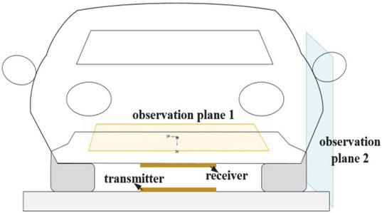
Figure 7 Target plane of magnetic leakage around the vehicle.
Different from the back propagation neural network, the weight values on the hidden layer of ELM do not need to be adjusted during the training process, featuring high solution efficiency and satisfactory performance of generalization [35]. The principle of ELM can be described as follows. For each input sample , the activation values of the neurons on the hidden layer can be expressed as:
| (11) |
where represents the activation function, represents the input weight vector of the l-th neuron, and represents the corresponding bias term, which are all randomly initialized and remaining constant during the training process of the model. The main task of ELM is to calculate the optimal weight values from hidden layer to output layer. Output can be expressed as a form of linear combination:
| (12) | |
| (13) |
To minimize the overall prediction error of the samples, the optimal weight matrix can be derived as:
| (14) |
where represents the matrix of hidden layer activation values and represents the target output matrix. In the ELM surrogate model established in this paper, the length of the shield coil L, the width of the shield coil W, the ring width of the ferrite groove H, and the depth of the ferrite groove D are taken as the input variables of the neural network model. The output variables include system transmission efficiency as well as maximum leakage flux density on observation planes 1 and 2. Thus, the number of nodes of the input and output layers of the neural network are set as 4 and 3. The modeling of ELM is the first step in the optimization design process of the electromagnetic shielding structure, which lays the foundation for the subsequent use of the optimization algorithm.
4.2 Multi-objective optimization process
As mentioned in the previous section, due to the multiple optimization objectives analyzed, this paper uses the multi-objective algorithm to solve the optimization design issue of the electromagnetic shielding structure.
The multi-objective particle swarm optimization (MOPSO) is an evolutionary algorithm improved on the basis of ordinary PSO, featuring better global search and convergence performance, which has been widely used in the solution of complex engineering problems. In this study, MOPSO is used for the optimization design of active and passive shielding structures. The basic idea of MOPSO is to divide the solution space into multiple sub-regions and search within each sub-region. Different from traditional PSO, MOPSO uses the relationship of Pareto dominance to evaluate the fitness of a particle [36, 37]. One particle is defined as dominating another particle if it outperforms the other particle on all objective functions. Only non-dominated particles can enter into the Pareto front. The solution process of MOPSO can be described as follows:
[(1)]
(1) Randomly initialize the position of the individual particles.
(2) Calculate the fitness of each individual particle and determine the non-dominated individuals according to the relationship of Pareto dominance. For a certain individual particle, the dominated set indicates the set of particles with worst fitness, and the non-dominated set indicates the set of particles with best fitness.
(3) Update the step size and position of each individual particle. The new step size and position of each particle is calculated according to the current status, then the fitness of particles and Pareto front are updated according to the relationship of Pareto dominance. If one certain particle becomes the new Pareto optimal solution, it will be added to the Pareto front; the solutions dominated will be removed.
(4) Repeat steps (2) and (3) until termination conditions are reached.
In summary, the steps of the optimization method can be described as follows. First, the optimization variables of shielding structure as well as the system optimization objectives are sampled through numerical simulation, which are taken as the training samples for the ELM surrogate model. When the training accuracy of the model reaches the requirements, the optimization objective value can be accurately predicted. The MOPSO algorithm is combined to search the optimal shielding structural variables under the premise of considering system transfer efficiency as well as the magnetic leakage flux density as the optimization target. We will eventually obtain the ideal optimization design parameters of the shielding structure. The overall procedure of the optimization method is depicted in Fig. 8.
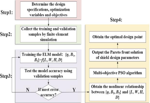
Figure 8 Overall optimization framework of hybrid shielding structure.
5 PERFORMANCE VERIFICATION
This paper establishes the finite element method (FEM) numerical simulation model of an electric vehicle’s WPT system in COMSOL software, which is shown in Fig. 9. The parameters of the vehicle’s body size are as follows: length of 4.5 m, width of 2 m, height of 1.5 m, which are consistent with the volume size of common domestic vehicles on the market [38]. The material of the vehicle’s body is set as aluminum, the materials of the tires and windows of the vehicle are respectively set as rubber and tempered glass, and the material of the coil groups is set as copper.
This paper establishes the human body model of adult male for analyzing the impact of the WPT system on human electromagnetic exposure safety, whose height and weight are respectively set as 1.8 m and 75 kg. The working frequency of the electric vehicle’s WPT system is set as 85 kHz, corresponding to human body tissue’s conductivity and relative permittivity respectively as 0.27 S/m and 5400 [39]. The electromagnetic exposure dose of human body is quantified using multi-physics field FEM, which is used to evaluate whether there exists potential threats to human health.
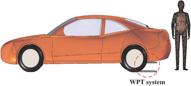
Figure 9 Simulation model of wireless power transmission scenario of electric vehicle.
According to the relevant test standards specified in SAETIRJ954, the test plane of magnetic leakage field is set on the side and above the WPT system in the practical scenario, respectively as 0.8 m away from the central WPT system coupling mechanism [40], whose position is shown in Fig. 7.
To verify the electromagnetic shielding effect of the proposed active and passive shielding structure in this study, this section arbitrarily sets the initial structural design parameters of the shielding structure as shown in Table 1. It should be noted that the structural parameters in Table 1 are not the eventual optimized design results, just for verifying whether the proposed shielding structure has the effect of weakening the magnetic leakage field for the WPT system.
Table 1 Initial structural parameters of active and passive shielding
| Active Shielding | 273 mm | |
| 38 mm | ||
| Passive Shielding | 23 mm | |
| 127 mm |
The simulation results of the magnetic leakage field distribution are as follows. On observation plane 1, comparison results of magnetic flux with and without ferrite groove passive shielding are depicted in Fig. 10.
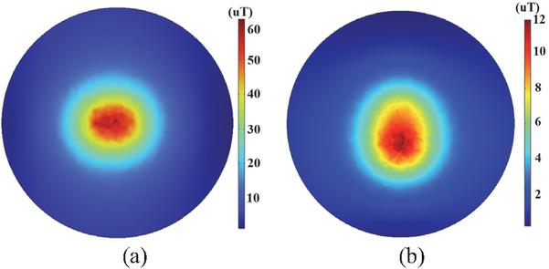
Figure 10 Comparison of magnetic leakage flux on plane 1 (a) without ferrite and (b) with ferrite.
It can be seen that the magnetic flux density of observation plane 1 is decreased by 80%, thus the ferrite groove can weaken the leaking electromagnetic magnetic field of the area above the WPT system. When passengers sit in the back seats of the vehicle, the electromagnetic exposure safety issues are alleviated. On the observation plane 2, the comparison results of magnetic leakage flux with and without active shielding coils are shown in Fig. 11.
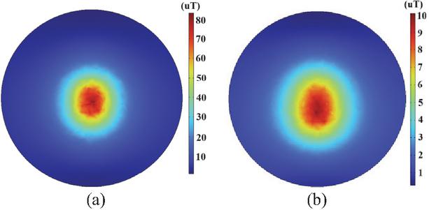
Figure 11 Comparison of magnetic leakage flux on plane 2 (a) without shield coil and (b) with shield coil.
It can be seen that the magnetic leakage flux density of observation plane 2 is decreased by 87.5%. Thus, the shield coils can effectively suppress the lateral leaking EMF. Combined with actual scenarios, when passengers stand at the side of the vehicle, electromagnetic radiation hazards are reduced.
Considering that the varying environmental temperatures in real situations may affect the performance of the shielding structure, this paper builds a temperature coupled physical field in the numerical simulation, analyzing the varying characteristics of the maximum magnetic leakage flux density on the target plane with changes of temperature, shown in Fig. 12.
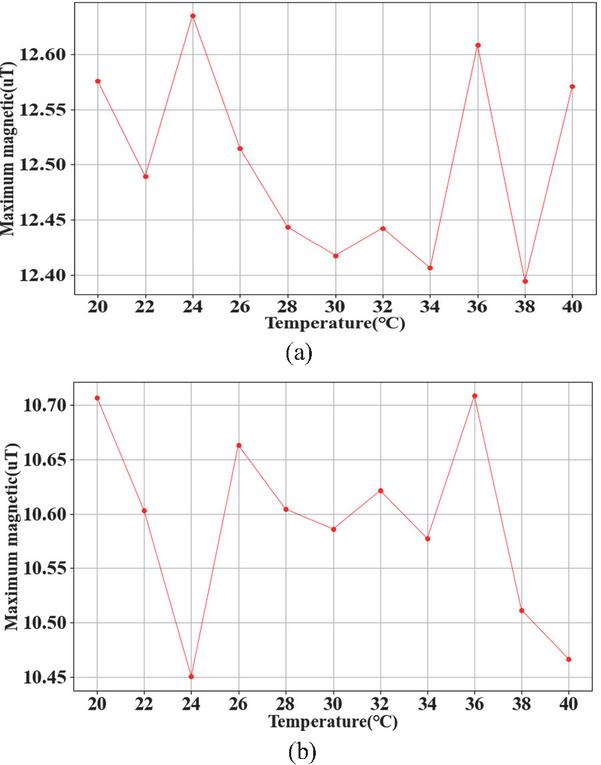
Figure 12 Analysis of the influence of environmental temperature on electromagnetic shielding performance. (a) Varying magnetic leakage with the temperature on plane 1 and (b) varying magnetic leakage with the temperature on plane 2.
It can be concluded that the change of external temperature has minimal impact on the performance of the proposed electromagnetic shielding structures, reflecting robustness for change of environment conditions. In the analysis of shielding structure optimization design, ELM is used for predicting the optimization objectives. To verify the performance of the trained ELM model, this paper uses the test sample to obtain the output values of the model and comparing it with the FEM results, as shown in Fig. 13.
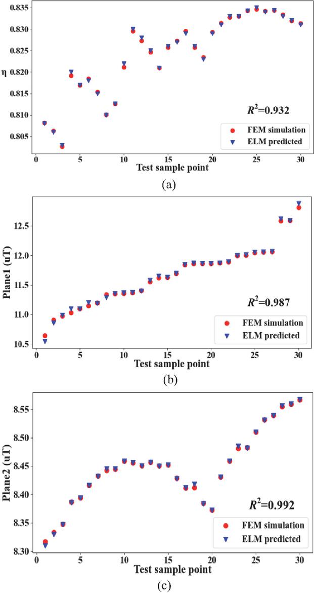
Figure 13 Comparison of ELM prediction and FEM simulation results. (a) Comparison results of system transfer efficiency, (b) comparison results of leakage flux on plane 1, and (c) comparison results of leakage flux on plane 2.
This paper takes the determination coefficient (R2) as an evaluation indicator for ELM model performance, which can intuitively reflect regression quality and prediction error distribution of the surrogate model [41]. A total of 30 sample points were tested and it can be seen that FEM and ELM have almost the same solution accuracy for each optimization objective, demonstrating the effectiveness of the ELM prediction method.
On this basis, the MOPSO algorithm was adopted for optimization of electromagnetic shielding structural parameters. The intervals of the selected optimization variables L, W, D, and H were set as [270 mm, 280 mm], [35 mm, 45 mm], [15 mm, 25 mm], and [120 mm, 130 mm], respectively. This paper set population size and maximum iteration times of the algorithm as 30 and 50. Implementing the optimization calculation can obtain the Pareto front solution results of each objective, shown in Fig. 14.
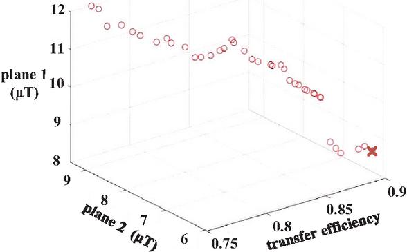
Figure 14 Pareto front solution results of three-objective PSO.
The optimal solution of shielding design parameters is marked by a cross in Fig. 14, which features higher transfer efficiency and lower electromagnetic exposure indicators, which is more in line with the needs of electric vehicle users. Table 2 shows the shielding structural parameter groups before and after optimization as well as the corresponding optimization target values.
In practical situations, there exist factors that could affect the electrical performance of the WPT system. Thus, it is necessary to carry out uncertainty quantification analysis for the work scenario of the WPT system [42]. Considering the spatial dislocation scenario of the coil groups of the WPT coupling mechanism, this study lists the relevant random variables as follows: transmission distance d, horizontal displacement of the coil groups , , and deviation angle of the coil groups , which are shown in Table 3. U represents uniform distribution, the Latin hypercube method is used for sampling the uncertain variables in this study, and the comparison results of various optimization objective’s probability distribution before and after optimization are shown in Fig. 15.
Table 2 Comparison of various parameter indicators before and after optimization
| (mm) | (mm) | (mm) | (mm) | (T) | (T) | ||
| Original | 273 | 38 | 23 | 127 | 0.79 | 11.3 | 9.7 |
| Optimized | 275 | 36 | 19 | 124 | 0.91 | 7.5 | 6.2 |
Table 3 Uncertain variables considered in the practical application of the WPT system
| Variables | Distribution Range | Unit |
| d | U (0.19, 0.21) | m |
| x | U (0, 0.02) | m |
| y | U (0, 0.02) | m |
| U (0, 90) | ∘ |
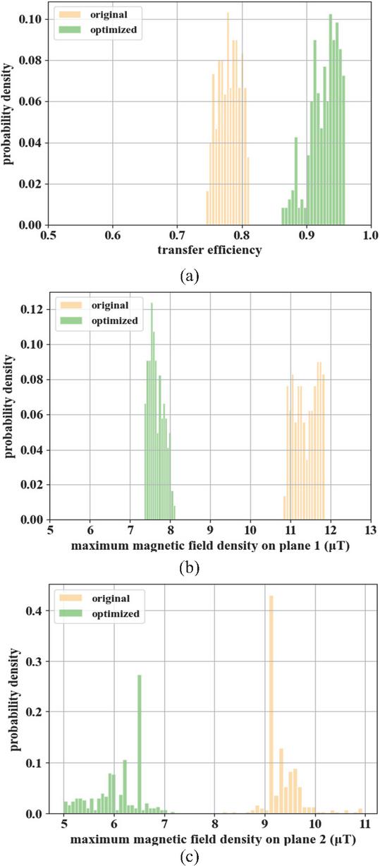
Figure 15 Probability distribution of various optimization target values before and after optimization. (a) Comparison of probability distribution of transfer efficiency, (b) comparison of probability distribution of maximum magnetic leakage flux density on plane 1, and (c) comparison of probability distribution of maximum magnetic leakage flux density on plane 2.
It can be concluded that under the interference of external uncertain factors, the transfer efficiency of the WPT system is more likely to be at a higher level after optimization. Meanwhile the risk of electromagnetic exposure is also decreased. Average transfer efficiency before and after optimization is 0.78 and 0.93, respectively, which is enhanced by 19.2%. Maximum magnetic leakage field density on observation plane 1 is 11.37 T and 7.66 T, respectively, before and after optimization, which is reduced by 35.1%. Maximum magnetic leakage field density on observation plane 2 is 9.35 T and 6.07 T, respectively, before and after optimization, which is reduced by 32.6%. Intensity of magnetic leakage field around the vehicle body are far less than the threshold (27 T) specified by ICNIRP guidelines, which improves the electromagnetic exposure safety protection effect.
In addition, this study takes the scene of a passenger standing near the vehicle as the research case, calculating the specific absorption ratio (SAR) value distribution of the whole human body by finite element numerical simulation Comparison results before and after optimization are depicted in Fig. 16.
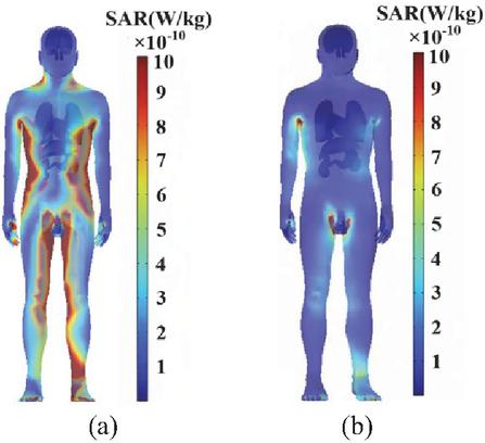
Figure 16 SAR value distribution of human body near the WPT system (a) non-optimized and (b) optimized.
SAR value can accurately reflect the electromagnetic radiation dose absorbed by unit mass of human tissue in unit time [43]. Taking SAR value as the evaluation indicator can more scientifically reflect the impact of external EMFs on human health.
From the above comparison results, it can be seen that the negative impact of a WPT system on the electromagnetic exposure safety of a human body is reduced after optimization, which features practical significance for electromagnetic safety protection of drivers or passengers in daily situations.
Thus, the proposed active and passive shielding structure and its multi-objective optimization method can effectively improve the comprehensive performance of the WPT system, which provides efficient solutions for the design of shielding structures of electric vehicle’s WPT systems. In the long term, improvement of electromagnetic shielding measures can promote faster development of WPT technology of electric vehicle, which is in line with the future trend of intelligent transportation developments.
6 CONCLUSION
This paper proposes a hybrid active and passive shielding method for mitigating the leaking magnetic field from an electric vehicle’s WPT system. The ferrite grooves are covered on the back of the WPT receiving coil, realizing reduction of the vertical magnetic leakage field above the coupling mechanism. The shield coils are placed on four sides of the WPT transmitter, effectively reducing the lateral magnetic leakage field outside the coupling mechanism. Moreover, this paper establishes the optimization framework based on multi-objective particle swarm and ELM surrogate model, carrying out the optimization of hybrid shielding structural parameters, realizing the enhancement of transfer capability and electromagnetic shielding performance. In addition, combined with practical scenarios of electric vehicle charging, the paper also conducts uncertainty quantification analysis for the electrical performance of the WPT system, comparing the probability density distribution of various target values before and after optimization. Average transfer efficiency is improved by 19.2%, average value of vertical and lateral magnetic leakage field density are reduced by 35.1% and 32.6%, respectively, and the electromagnetic exposure indicator of a human body near the WPT system is significantly reduced.
ACKNOWLEDGMENT
This work was supported in part by the Jilin Scientific and Technological Development Program under Grant 20240101117JC, and by Key Laboratory for Comprehensive Energy Saving of Cold Regions Architecture of Education, Jilin Jianzhu University under Grant JLJZHDKF202203.
References
[1] K. Chen, J. Pan, Y. Yang, and K. Cheng, “Stability improvement and overshoot damping of SS compensated EV wireless charging systems with user-end buck converters,” IEEE Transactions on Vehicular Technology, vol. 71, no. 8, pp. 8354–8366, Aug. 2022.
[2] O. N. Nezamuddin, C. L. Nicholas, and E. C. dos Santos, “The problem of electric vehicle charging: State-of-the-art and an innovative solution,” IEEE Transactions on Intelligent Transportation Systems, vol. 23, no. 5, pp. 4663–4673, May 2022.
[3] J. Liu, Z. Liu, W. Chen, X. Sun, and H. Su, “An optimized coil array and passivity-based control for receiving side multilevel connected DC-DC converter of dynamic wireless charging,” IEEE Transactions on Vehicular Technology, vol. 71, no. 4, pp. 3715–3726, Apr. 2022.
[4] Z. Luo, Y. Zhao, M. Xiong, X. Wei, and H. Dai, “A self-tuning LCC/LCC system based on switch-controlled capacitors for constant-power wireless electric vehicle charging,” IEEE Transactions on Industrial Electronics, vol. 70, no. 1, pp. 709–720, Jan. 2023.
[5] M. Mohammad, E. T. Wodaj, S. Choi, and M. E. Elbuluk, “Modeling and design of passive shield to limit EMF emission and to minimize shield loss in unipolar wireless charging system for EV,” IEEE Transactions on Power Electronics, vol. 34, no. 12, pp. 12235–12245, Dec. 2019.
[6] S. Cruciani, T. Campi, F. Maradei, and M. Feliziani, “Active shielding design for wireless power transfer systems,” IEEE Transactions on Electromagnetic Compatibility, vol. 61, no. 6, pp. 1953–1960, Dec. 2019.
[7] S. Cruciani, T. Campi, F. Maradei, and M. Feliziani, “Active shielding design and optimization of a wireless power transfer (WPT) system for automotive,” Energies, vol. 13, no. 21, pp. 1–12, Oct. 2020.
[8] M. Mi, Q. Yang, Y. Li, P. Zhang, and W. Zhang, “Multi-objective active shielding coil design for wireless electric vehicle charging system,” IEEE Transactions on Magnetics, vol. 58, no. 2, pp. 1–5, Feb. 2022.
[9] T. Campi, S. Cruciani, F. Maradei, and M. Feliziani, “Magnetic field mitigation by multicoil active shielding in electric vehicles equipped with wireless power charging system,” IEEE Transactions on Electromagnetic Compatibility, vol. 62, no. 4, pp. 1398–1405, Aug. 2020.
[10] Y. Li, S. Zhang, and Z. Cheng, “Double-coil dynamic shielding technology for wireless power transmission in electric vehicles,” Energies, vol. 14, no. 17, pp. 1–20, Sep. 2021.
[11] M. Budhia, G. A. Covic, and J. T. Boys, “Design and optimization of circular magnetic structures for lumped inductive power transfer systems,” IEEE Transactions on Power Electronics, vol. 26, no. 11, pp. 3096–3108, Nov. 2011.
[12] Q. Zhu, D. Chen, L. Wang, C. Liao, and Y. Guo, “Study on the magnetic field and shielding technique for an electric vehicle oriented wireless charging system,” Transactions of China Electrotechnical Society, vol. 30, pp. 143–147, 2015.
[13] M. Mohammad, O. C. Onar, V. P. Galigekere, G. Su, and J. Wilkins, “Magnetic shield design for the double-D coil-based wireless charging system,” IEEE Transactions on Power Electronics, vol. 37, no. 12, pp. 15740–15752, Dec. 2022.
[14] B. S. Gu, T. Dharmakeerthi, S. Kim, M. J. O’Sullivan, and G. A. Covic, “Optimized magnetic core layer in inductive power transfer pad for electric vehicle charging,” IEEE Transactions on Power Electronics, vol. 38, no. 10, pp. 11964–11973, Oct. 2023.
[15] Z. Dai, X. Zhang, T. Liu, C. Pei, T. Chen, R. Dou, and J. Wang, “Magnetic coupling mechanism with omnidirectional magnetic shielding for wireless power transfer,” IEEE Transactions on Electromagnetic Compatibility, vol. 65, no. 5, pp. 1565–1574, Oct. 2023.
[16] Z. Li, W. Zhang, Z. Gan, and B. Li, “Study on composite structure of tian-font magnetic shielding and anti-series active coils for wireless power transfer system,” CPSS Transactions on Power Electronics and Applications, vol. 10, no. 1, pp. 97–109, Mar. 2025.
[17] X. Zhang, S. Liu, R. Dou, C. Hao, L. Zhao, P. Zhang, and Q. Yang, “A novel hybrid shielding method with single-source active topology and efficiency stability for wireless power transfer,” IEEE Transactions on Magnetics, vol. 59, no. 11, pp. 1–6, Nov. 2023.
[18] Y. Li, K. Xie, Y. Ying, and Z. Li, “An improved hybrid shielding with LC coil for wireless power transfer system,” IEEE Transactions on Electromagnetic Compatibility, vol. 64, no. 3, pp. 720–731, June 2022.
[19] H. Zhao, K. Liu, S. Li, F. Yang, S. Cheng, H. H. Eldeeb, J. Kang, and G. Xu, “Shielding optimization of IPT system based on genetic algorithm for efficiency promotion in EV wireless charging applications,” IEEE Transactions on Industry Applications, vol. 58, no. 1, pp. 1190–1200, Jan. 2022.
[20] Z. Luo, X. Wei, M. G. S. Pearce, and G. A. Covic, “Multi-objective optimization of inductive power transfer double-D pads for electric vehicles,” IEEE Transactions on Power Electronics, vol. 36, no. 5, pp. 5135–5146, May 2021.
[21] Y. Pei, L. Pichon, B. Y. Le, M. Bensetti, and P. Dessante, “Fast shielding optimization of an inductive power transfer system for electric vehicles,” IEEE Access, vol. 10, pp. 91227–91234, Sep. 2022.
[22] J. Yi, P. Yang, Z. Li, P. Kong, and J. Li, “Mutual inductance calculation of circular coils for an arbitrary position with a finite magnetic core in wireless power transfer systems,” IEEE Transactions on Transportation Electrification, vol. 9, no. 1, pp. 1950–1959, Mar. 2023.
[23] T. Zhang, G. Wei, R. Li, J. Feng, and C. Zhu, “Completely analytical model of inductance for circular coils with bilateral finite magnetic cores and Al plates in WPT systems,” IEEE Transactions on Transportation Electrification, vol. 10, no. 3, pp. 6129–6140, Sep. 2024.
[24] R. Xie, R. Liu, X. Chen, X. Mao, X. Li, and Y. Zhang, “An interoperable wireless power transmitter for unipolar and bipolar receiving coils based on three-switch dual-output inverter,” IEEE Transactions on Power Electronics, vol. 39, no. 2, pp. 1985–1989, Feb. 2024.
[25] G. Rituraj, B. K. Kushwaha, and P. Kumar, “A unipolar coil arrangement method for improving the coupling coefficient without ferrite material in wireless power transfer systems,” IEEE Transactions on Transportation Electrification, vol. 6, no. 2, pp. 497–509, June 2020.
[26] Z. Luo, S. Nie, M. Pathmanathan, W. Han, and P. W. Lehn, “3-D analytical model of bipolar coils with multiple finite magnetic shields for wireless electric vehicle charging systems,” IEEE Transactions on Industrial Electronics, vol. 69, no. 8, pp. 8231–8242, Aug. 2022.
[27] Z. Luo and X. Wei, “Analysis of square and circular planar spiral coils in wireless power transfer system for electric vehicles,” IEEE Transactions on Industrial Electronics, vol. 65, no. 1, pp. 331–341, Jan. 2018.
[28] G. Rituraj and P. Kumar, “A new magnetic structure of unipolar rectangular coils in WPT systems to minimize the ferrite volume while maintaining maximum coupling,” IEEE Transactions on Circuits and Systems II: Express Briefs, vol. 68, no. 6, pp. 2072–2076, June 2021.
[29] H. Zhuang, W. Wang, and G. Yan, “Ferrite concentrating and shielding structure design of wireless power transmitting coil for inductively coupled capsule robot,” IEEE Transactions on Biomedical Circuits and Systems, vol. 17, no. 1, pp. 45–53, Feb. 2023.
[30] J. Shin, S. Shin, Y. Kim, S. Ahn, S. Lee, G. Jung, S. J. Jeon, and D. H. Cho, “Design and implementation of shaped magnetic-resonance-based wireless power transfer system for roadway-powered moving electric vehicles,” IEEE Transactions on Industrial Electronics, vol. 61, no. 3, pp. 1179–1192, Mar. 2014.
[31] A. Tejeda, C. Carretero, J. T. Boys, and G. A. Covic, “Ferrite-less circular pad with controlled flux cancelation for EV wireless charging,” IEEE Transactions on Power Electronics, vol. 32, no. 11, pp. 8349–8359, Nov. 2017.
[32] S. Y. Choi, B. W. Gu, S. W. Lee, W. Y. Lee, J. Huh, and C. T. Rim, “Generalized active EMF cancel methods for wireless electric vehicles,” IEEE Transactions on Power Electronics, vol. 29, no. 11, pp. 5770–5783, Nov. 2014.
[33] W. Zhang, J. C. White, R. K. Malhan, and C. C. Mi, “Loosely coupled transformer coil design to minimize EMF radiation in concerned areas,” IEEE Transactions on Vehicular Technology, vol. 65, no. 6, pp. 4779–4789, June 2016.
[34] Y. Pei, L. Pichon, B. Y. Le, M. Bensetti, and P. Dessante, “Fast shielding optimization of an inductive power transfer system for electric vehicles,” IEEE Access, vol. 10, pp. 91227–91234, Aug. 2022.
[35] N. Liu and H. Wang, “Ensemble based extreme learning machine,” IEEE Signal Processing Letters, vol. 17, no. 8, pp. 754–757, Aug. 2010.
[36] A. Elhossini, S. Areibi, and R. Dony, “Strength Pareto particle swarm optimization and hybrid EA-PSO for multi-objective optimization,” Evolutionary Computation, vol. 18, no. 1, pp. 127–156, Mar. 2010.
[37] S. Wang and A. Zhou, “Leader prediction for multiobjective particle swarm optimization,” IEEE Transactions on Evolutionary Computation, vol. 29, no. 4, pp. 1356–1370, Aug. 2025.
[38] Q. Wang, W. Li, J. Kang, and Y. Wang, “Electromagnetic safety evaluation and protection methods for a wireless charging system in an electric vehicle,” IEEE Transactions on Electromagnetic Compatibility, vol. 61, no. 6, pp. 1913–1925, Dec. 2019.
[39] A. Arduino, O. Bottauscio, M. Chiampi, L. Giaccone, I. Liorni, N. Kuster, L. Zilberti, and M. Zucca, “Accuracy assessment of numerical dosimetry for the evaluation of human exposure to electric vehicle inductive charging systems,” IEEE Transactions on Electromagnetic Compatibility, vol. 62, no. 5, pp. 1939–1950, Oct. 2020.
[40] Y. Li, K. Xie, Y. Ying, and Z. Li, “An improved hybrid shielding with LC coil for wireless power transfer system,” IEEE Transactions on Electromagnetic Compatibility, vol. 64, no. 3, pp. 720–731, June 2022.
[41] Y. Wang, F. Wang, Y. Tian, A. N. Sun, and B. Liu, “Surrogate-assisted multiobjective optimization of double-D coil for inductive power transfer system with LCC-LCC compensation network,” IEEE Transactions on Industrial Electronics, vol. 71, no. 9, pp. 10612–10624, Sep. 2024.
[42] T. Wang, Q. Yu, B. Li, G. Lv, Y. Wu, and S. Guan, “Uncertainty quantification of human electromagnetic exposure from electric vehicle wireless power transfer system,” IEEE Transactions on Intelligent Transportation Systems, vol. 24, no. 8, pp. 8886–8896, Aug. 2023.
[43] A. A. S. Mohamed, A. Meintz, P. Schrafel, and A. Calabro, “Testing and assessment of EMFs and touch currents from 25 kW IPT system for medium duty EVs,” IEEE Transactions on Vehicular Technology, vol. 68, no. 8, pp. 7477–7487, Aug. 2019.
Biographies

Yangyun Wu received the B.S. degree in architectural electricity and intelligence from the College of Electrical and Informational Engineering, Jilin University of Architecture and Technology, Changchun, Jilin, China, in 2018, the M.S. degree in electrical engineering from the College of Electrical and Computer Science, Jilin Jianzhu University, Changchun, Jilin, in 2021. He is currently working toward the Ph.D. degree in electrical engineering from the College of Instrumentation and Electrical Engineering, Jilin University. His research interests include the uncertainty quantification and optimal design strategy of EV’s wireless power transfer system.

Tianhao Wang received the B.S. degree in electrical engineering and the Ph.D. degree in vehicle engineering from Jilin University, Changchun, Jilin, China, in 2010 and 2016, respectively. From 2016 to 2019, he was a Postdoctoral Researcher with the Department of Science and Technology of Instrument, Jilin University. He is currently an Assistant Professor with the College of Instrumentation and Electrical Engineering, Jilin University. His research interest includes numerical and experimental studies of crosstalk in complex cable bundles, with a particular emphasis on considering parameter variability using efficient statistical approaches.

Quanyi Yu received the B.S. and the M.S. degrees from the College of Communication Engineering, Jilin University, Changchun, Jilin, China, in 2016 and 2020, respectively, where he is pursuing the Ph.D. degree. His research interests include uncertainty quantification and electromagnetic compatibility of EVs.

Gang Lv received the master degree of electronic circuit and system in college of electronic science & engineering, Jilin University, Changchun, Jilin, China, in 2008. He came on board into National Automotive Quality supervision & Inspection Center (Changchun) after graduated. He is currently the head of the EMC department. He is mainly in charge of the EMC performance in vehicle type approval under the direction of Ministry of Industry and Information Technology (MIIT) and Certification and Accreditation Administration of the P.R.C. He always focuses on test methods improving and National Standards edit and amendment in EMC domain.
He has joined teams to be responsible for EMC part of “Test and Evaluation of autonomous electric vehicle” subject which is released by Ministry of Science and Technology (MOST) and “Research on real-time concurrent Simulation test technology of Multi-source Sensor information of Intelligent Networked Vehicle” which is released by Science and Technology Department of Jilin Province.

Yaodan Chi received the B.S. degree in electronic information engineering from the Jilin University of Technology, Changchun, Jilin, China, in 1998, and the master’s degree in testing and measuring technology and instruments and the Ph.D. degree in science and technology of instrument from Jilin University, Changchun, Jilin, in 2004 and 2018, respectively. She is currently the Vice Director of the Jilin Provincial Key Laboratory of Architectural Electricity and Comprehensive Energy Saving. Her research interests include the uncertainty analysis approaches in electromagnetic compatibility simulation and building equipment intelligent integration technology.

Shanshan Guan received the B.S. degree in precision instruments and machinery and the Ph.D. degree in measurement technology and instruments from Jilin University, Changchun, Jilin, China, in 2008 and 2012, respectively. In 2019, she was a Visiting Scholar at the Southern University of Science and Technology, Shenzhen. She is currently an Associate Professor with the College of Instrumentation and Electrical Engineering, Jilin University. Her research interests include forward modeling and inverse algorithms of EM fields, and the development of electromagnetic instruments.
ACES JOURNAL, Vol. 41, No. 01, 95–107
DOI: 10.13052/2026.ACES.J.410110
© 2026 River Publishers