Ultra-thin Coating Materials Sensor Based on Constitutive Parameters Near-zero Media
Si Hui Jia, Yu Wei Mao, Qiao Yu Li, Zi Jian Gao, Zi Peng Shan, and Yong Jin Zhou
1Shanghai Collaborative Innovation Center of Intelligent Sensing Chip Technology
Laboratory of Specialty Fiber Optics and Optical Access Networks, Shanghai University, Shanghai 200444, China
22820144@shu.edu.cn, maoyuwei@shu.edu.cn, 20820117@shu.edu.cn, zijiangao2333@shu.edu.cn
2State Key Laboratory of Millimeter Waves
School of Information Science and Engineering, Southeast University, Nanjing 210096, China
yjzhou@shu.edu.cn
Submitted On: February 28, 2025; Accepted On: June 16, 2025
ABSTRACT
Microwave absorbing materials, which serve as essential functional components, are increasingly vital to stealth systems in military equipment. Accurate measurement of the electromagnetic parameters of absorbing coatings is crucial for achieving stealth effects. This study introduces a high-precision curved microwave sensor based on constitutive parameters near-zero (CPNZ) media, which uses thickness and complex permittivity as key test parameters. The complex permittivity and thickness of several typical absorbing materials were evaluated and benchmarked against other sensors. The detection limit of a CPNZ sensor for curved thickness is 0.5 mm, and the relative error of relative dielectric constant is less than 8%. Given the material thickness and resonant frequency, the relative error in the inversion of the dielectric constant is less than 3%. The calculated values closely correspond with the reference values, highlighting the CPNZ sensor’s enhanced accuracy and reliability for material characterization.
Index Terms: Constitutive parameters near-zero media, high accuracy, microwave sensor, ultra-thin coating material.
I. INTRODUCTION
Material stealth technology is extensively applied in radar stealth design for ships, aircraft, missiles, and other platforms due to its superior stealth effect, ease of application, and lack of restrictions on body shape. Microwave absorbing materials, as vital military components, play an increasingly critical role in the stealth systems of military equipment [1]. To accurately design stealth absorbing materials, precise measurement of their complex dielectric constant is crucial for radar stealth applications [2–4]. To meet aerodynamic requirements, the carrier’s shape is often streamlined to reduce radar signal reflections. When applied to the carrier’s surface, the absorbing material bends, altering its electromagnetic parameters, and its thickness also affects absorbing performance. Therefore, accurate measurement of the complex permittivity of ultra-thin surface materials holds significant research value for radar defense system design. Since the 1940s, when Horner et al. used the perturbation method to measure the complex permittivity of materials, measurement technology has developed vigorously [5]. Numerous researchers worldwide have conducted extensive research on methods to measure complex permittivity, such as the free space method, transmission/reflection method, and resonance method [6]. As material performance requirements increase, new measurement technologies have been proposed [6–11]. Non-contact measurement methods are commonly employed to determine the complex permittivity and thickness of materials under test (MUT) [12]. However, these methods are primarily used to measure high-loss materials [12, 13], with measurement errors too large to accurately characterize low-loss dielectric materials [13, 14]. A magnetic dielectric material characterization sensor, based on an improved complex split-ring resonator, can simultaneously measure both complex permittivity and permeability changes [11]. By locating the highest field strengths of the electric and magnetic fields in two independent regions, the measured resonant frequency and quality factor can be analyzed to determine the real and imaginary parts of the complex permittivity and permeability. The relative permittivity and loss tangent of the measured materials range from 3.25 to 6.2 and 0.0022 to 0.027, respectively, providing accurate measurements for low-loss materials. Additionally, a dual-band nondestructive sensor for measuring relative permittivity based on a complementary split resonant ring has been developed [14]. The measured relative dielectric constant, loss tangent, and material thickness range from 2 to 10, 0 to 0.1, and 2 to 10 mm, respectively, with relative errors of permittivity and low-loss tangent less than 4% and 16.7%, indicating a high level of accuracy. However, these methods for measuring solid materials often neglect the influence of material thickness on the complex dielectric constant [7, 10]. In the nondestructive measurement of relative permittivity for objects with varying thicknesses, the measurement error increases as material thickness decreases. Yet, the measurement of the complex dielectric constant for ultra-thin curved materials has not been addressed in the existing work.
Microwave sensor measurement technology offers advantages such as high integration, measurement accuracy, and real-time performance, emerging as the leading technology for measuring complex permittivity [15, 16]. Metamaterials, artificial electromagnetic structures composed of subwavelength resonators, exhibit novel electromagnetic properties and are widely used in sensing, antennas, and stealth technology [17–19]. Among these metamaterials, constitutive parameters near-zero (CPNZ) media have garnered significant interest for their unique wave phenomena [20]. In printed circuit design, substrate-integrated photon doping facilitates the use of near-zero refractive index media in dielectric constant measurements [21, 22]. A small change in the relative dielectric constant of the measured object leads to a significant shift in the tunneling frequency, and the transmission coefficient amplitude decreases significantly with moderate doping loss, indicating that the near-zero refractive index medium is sensitive to doped complex permittivity [6, 23, 24]. This sensitivity has potential applications in material characterization, sensing, and related fields. For example, a wireless sensor system based on the relative permittivity near-zero effect measures the complex permittivity of liquids with relative errors of 3.72% and 9.67%, respectively, using only a small volume of liquid [23]. In addition to complex permittivity, microwave sensors based on relative permeability near-zero media can also measure the permeability of magnetic dielectric materials [24]. Research on sensing platforms based on relative permittivity near-zero metamaterials has demonstrated that relative permittivity near-zero sensors can detect changes in both the relative dielectric constant and position. However, effective transmission requires the waveguide height to exceed the relative permittivity near-zero channel height, complicating experimental verification [25]. The relative permittivity near-zero sensor is sensitive to both low-loss and high-loss materials, and relative permittivity near-zero medium doping allows for the measurement of materials of varying shapes by altering the doping configuration. Despite these advancements, the measurement of complex permittivity in ultra-thin curved surfaces using near-zero refractive index media sensors remains unexplored. To address the challenge of multi-parameter measurement for curved materials, this paper proposes a novel sensor structure based on CPNZ media with elliptical doping. High-accuracy measurements are achieved through optimization of the field distribution and implementation of a polynomial regression model parameter inversion.
In this paper, a high-precision curved microwave sensor based on CPNZ medium is proposed, focusing on the thickness and complex permittivity of curved materials as test parameters. The sensor is modeled and benchmarked against other advanced sensors. The sensor successfully achieves accurate measurement of the thickness and complex permittivity of curved materials.
II. STRUCTURES AND RESULTS
A. Design and simulation of CPNZ sensor
Considering the curvature distribution of typical curved surface coatings, the study adopts elliptical doping as a representative case to improve the generalizability and applicability of the proposed approach. This paper adopts elliptical doping, defines the operating frequency range between 1.5 GHz and 3 GHz, and uses electromagnetic simulation software CST to perform a full-wave simulation of the sensor. The relative permittivity near-zero cavity is modeled using a rectangular air waveguide operating near the cutoff frequency of the TE10 mode. The length and width of the rectangular air waveguide are L 260 mm and W 85 mm, respectively. The cutoff frequency of the simulated relative permittivity near-zero cavity is 1.97 GHz. The input and output terminals are both 50-ohm microstrip lines, connected via gradient microstrip lines. The dielectric substrate is F4B with a relative permittivity of 2.65 and a loss tangent of 0.002. The length and width of the entire structure are l 100 mm and w 76 mm, respectively. The substrate thickness is h 6.5 mm, and the diameter of the metal through-hole is d 2.4 mm. The hole spacing is s 4 mm and the copper thickness on the upper and lower surfaces of the dielectric substrate is 0.035 mm. The length of ceramic doping is X 50 mm, and the width of ceramic doping is Y 20 mm.
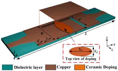
Figure 1: Structure diagram of CPNZ microwave sensor.
The overall schematic diagram of the sensor structure and the top view of the elliptical doping part are shown in Fig. 1. Figure 2 (a) presents the transmission curve S of the CPNZ structure, showing a resonant frequency at 1.97 GHz. To simulate effects that may be introduced during the actual fabrication process, we vary the lengths of the major and minor axes of the doping in the simulation, with a step of 0.2 mm. As shown in Fig. 2 (a), it can be seen that the fabrication tolerance has little impact on the results. The electric and magnetic field distributions of the CPNZ structure at 1.97 GHz are illustrated in Figs. 2 (b) and (c). The electric field is largely concentrated at the edge of the doping, while the magnetic field is primarily concentrated in the inner part of the doping. The local enhancement of the electric and magnetic fields makes the structure feasible to the precise measurement of small variations in the electromagnetic parameters of the material. The phase distribution of the magnetic field is illustrated in Fig. 2 (d). It can be seen that the phase of the magnetic field is uniformly distributed at the resonant frequency. At this frequency, the equivalent relative permittivity and equivalent relative permeability of the doped relative permittivity near-zero cavity are both zero, consistent with the characteristics of CPNZ media.
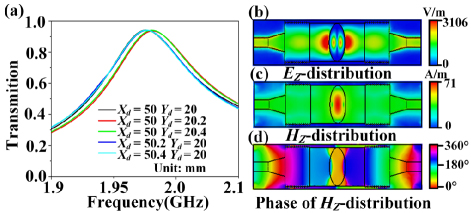
Figure 2: Simulation results of CPNZ sensor: (a) transmission coefficients, (b) electric field distribution, (c) magnetic field distribution, and (d) magnetic field phase distribution.
B. Sensor simulation data acquisition
To better measure the thickness and complex permittivity of the absorbing material coated, elliptical doping grooves were employed for applying the absorbing material. The structure after grooving is shown in Fig. 3 (a). Due to processing technology limitations, the groove wall thickness was selected as 0.7 mm. In the absence of coating material, the transmission curve after grooving is shown in Fig. 3 (b), demonstrating a transmission peak at 2.9 GHz. To simulate effects that may be introduced during the actual fabrication process, we vary the lengths of the major and minor axes of the elliptical doping trench, in the simulation, with a step of 0.2 mm. In Fig. 3 (b), it can be seen that the fabrication tolerance in the minor axis has a greater impact on the results. Grooving altered the elliptical doping, resulting in a nonzero equivalent relative permeability, while the equivalent relative permittivity remained unaffected. As a result, the resonant frequency undergoes a blue shift, and the field distribution inside the doping is altered. Specifically, the magnetic field inside the doping is no longer uniformly distributed, and the electric field shifts from being concentrated at the doping edge prior to grooving to the doping interior, while the magnetic field shifts from being concentrated inside the doping prior to grooving to the doping edge, as shown in Figs. 3 (c) and (d). The local concentration of the electric field inside the doping is advantageous for accurately measuring the thickness and complex permittivity of curved materials.
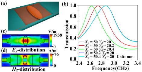
Figure 3: (a) Structure diagram after grooving (upper metal is hidden), (b) transmission coefficients, (c) electric field distribution, and (d) magnetic field distribution.
Next, the designed sensor is employed to simulate and analyze the thickness and complex permittivity of the absorbing material. The absorbing material bends when coated on the surface of the elliptical groove, which is made of ceramic doping, as shown in Fig. 4 (a). According to the absorption mechanism of the coating, its performance depends not only on its complex permittivity but also on its thickness. Therefore, the coating thickness must be analyzed before measuring its complex permittivity. Figure 4 (b) displays the corresponding transmission curves for different thicknesses, where the thickness is given in millimeters (mm). It is evident that the sensor is sensitive to slight changes in coating thickness. When the coating thickness is increased by 0.25 mm, it can be clearly observed that the peak of the resonance frequency is shifted to the lower frequency by about 40 MHz, and when the coating thickness is increased by 0.1 mm, the peak of the resonance frequency is shifted to the lower frequency by about 17 MHz. The simulation results demonstrate a consistent red shift in resonance frequency with increasing coating thickness.
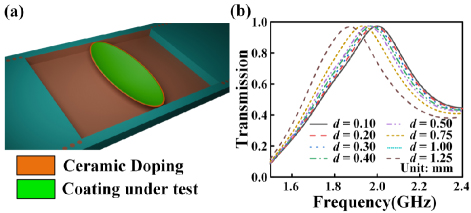
Figure 4: (a) Schematic diagram after loading absorbing coating under test and (b) transmission coefficients corresponding to different thicknesses.
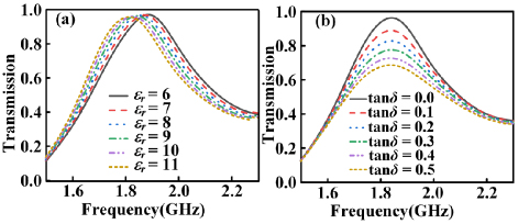
Figure 5: (a) Transmission coefficients corresponding to different relative permittivity and (b) transmission coefficients corresponding to different loss tangent.
If the coating is too thin, absorption and stealth performance will be markedly reduced. Conversely, if the coating is too thick, the maneuverability of the aircraft or weapon will be compromised. Here, the chosen thickness for the absorbing coating is 1.3 mm. The electric field of the sensor varies with changes in the complex permittivity of the absorbing coating, which is manifested in changes to the resonant frequency and transmission amplitude of the sensor. The relative permittivity of the absorbing coating increases from 6 to 11 in steps of 0.5, and the loss tangent of the coating increases from 0 to 1.3 in steps of 0.1. This process results in 154 sets of data. Figure 5 (a) shows the transmission curve when the loss tangent of the absorbing coating is zero and only the relative permittivity is varied. It is evident that as the relative permittivity of the absorbing coating gradually increases, the resonant frequency of the sensor red-shifts accordingly. When the relative permittivity of the absorbing coating is 8, only the loss tangent of the coating is varied, and its transmission curve is shown in Fig. 5 (b). It is observed that as the loss tangent of the coating increases successively, the sensor’s transmission amplitude decreases correspondingly. The simulation results demonstrate a clear relation between the transmission coefficient for both the relative permittivity and loss tangent. Additionally, the absorbing performance of the coatings is shown to be closely dependent on both their electromagnetic properties and thickness. To evaluate the sensitivity and the detection limit of the sensor, a polynomial regression model is developed.
C. Parameter inversion based on polynomial regression model
The absorbing effect of the coating depends heavily on its thickness and complex permittivity. This paper employs a polynomial regression model to establish an inversion model based on simulated data at different thicknesses, thus enabling the determination of the detection limit of coating thickness using the CPNZ media sensor. First, absorbing coatings with thicknesses of 0.3 mm, 0.4 mm, and 0.5 mm are selected, where the resonant frequency is primarily determined by the relative permittivity of the coating. Through the extraction of simulation results, the relationship between relative permittivity and resonant frequency of coatings with thicknesses of 0.3 mm, 0.4 mm, and 0.5 mm is derived through a quadratic regression model, as shown in Figs. 6 (a), (b), and (c), respectively. The coefficients of determination for thicknesses of 0.3 mm, 0.4 mm, and 0.5 mm are 0.9699, 0.9870, and 0.9877, respectively. The obtained quadratic equations are given in equations (1-3). It can be concluded that the minimum sensitivities are 8.21 MHz/RIU, 7.11 MHz/RIU, and 10.45 MHz/RIU at coating thicknesses of 0.3 mm, 0.4 mm, and 0.5 mm, respectively:
| (1) |
| (2) |
| (3) |
where p represents the relative dielectric constant of the coating, and y represents the resonant frequency.
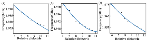
Figure 6: Relationship between relative permittivity of coating and resonant frequency: (a) 0.3 mm, (b) 0.4 mm, and (c) 0.5 mm.
To better determine the detection limit of the sensor’s coating thickness, the relative permittivity of substrates of six types of media with thicknesses of 0.3 mm, 0.4 mm, and 0.5 mm is inverted, and the relative errors for the three thicknesses are compared, as shown in Fig. 7. The relative error of measurement is defined as:
| (4) |
c represents the predicted inversion value of coating thickness, while c represents the reference value. When the coating thickness is 0.3 mm and 0.4 mm, the relative errors in permittivity exceed 10% for these thicknesses, but remain below 8% for a coating thickness of 0.5 mm, demonstrating high accuracy. Therefore, we determined that the minimum thickness detectable by the CPNZ media sensor is 0.5 mm, where e represents the relative error in the permittivity of the materials.
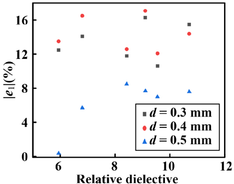
Figure 7: Relative error comparison of relative permittivity under different thickness.
We compare the performances of the CPNZ sensor with other works in Table 1. Santra and Limaye [6] evaluated cylindrical samples, reporting a minimum detectable thickness of 4 mm and a relative error of less than 5% in dielectric constant measurement. Wang et al. [14] investigated cubic samples, achieving a minimum detectable thickness of 2 mm with a relative error of less than 4%. The proposed sensor is tailored for ellipsoidal wave-absorbing coatings, achieving a lower detection limit of 0.5 mm and a relative error in dielectric constant measurement of less than 8%. These results indicate that the proposed method offers clear advantages in the non-destructive evaluation of thickness and electrical parameters in complex curved films, combining high sensitivity with low measurement error.
Table 1: Performance comparison with other works
| Ref. | Shape | Frequency Band (GHz) | Minimum Detectable Thickness | |e| |
| [6] | Cylinder | 3.2-4 | 4 mm | 5% |
| [14] | Cube | 2.8, 4.9 | 2 mm | 4% |
| This Work | Elliptic surface | 2.9 | 0.5 mm | 8% |
The resonant frequency of the sensor is influenced by both the relative permittivity and the thickness of the coating. We first consider the case without loss, that is, the loss tangent of the material is set to zero. The coating thickness increases from 0.5 mm to 1.5 mm with a step value of 0.1 mm, and the relative permittivity of the coating increases from 6 to 11 with a step value of 0.5, yielding a total of 121 data sets. In the simulation, the data are directly obtained, and the resonant frequency is then extracted. A polynomial regression model was used to nonlinearly fit the 121 data sets extracted above, producing the relationship surface between coating thickness, relative permittivity, and resonant frequency, as shown in Fig. 8. The coefficient of determination is 0.9961.
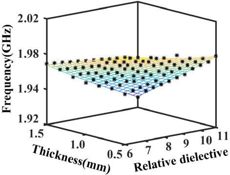
Figure 8: Relationship between relative permittivity and thickness of coating and resonant frequency.
Since the resonant frequency is related to both the relative permittivity and the thickness of the material, two inversion methods are available. First, the resonant frequency and relative permittivity are used to determine the thickness through the inversion model. Second, the resonant frequency and thickness are used to obtain the relative permittivity from the inversion model.
Four types of dielectric substrates with varying thicknesses and complex permittivity were selected, analyzed, and compared using the two inversion approaches. For the first inversion approach, when the relative permittivity and resonant frequency of the four materials are known, the relative error in material thickness, as shown in Table 2, is computed. Here, e represents the relative error of the material thickness, and the four materials are abbreviated as S, S, S, and S, respectively. The calculation equation for e, eis based on equation (1).
Table 2: The first inversion approach: Inversion thickness with known relative permittivity
| MUT | Reference Thickness (c) | Predicted Thickness (c) | |e| | |
| Rogers 4003(S) | 3.55 | 0.814 mm | 0.695 mm | 14.6% |
| FR4(S) | 4.4 | 0.814 mm | 0.710 mm | 12.8% |
| FR4(S) | 4.4 | 1.187 mm | 1.077 mm | 9.3% |
| Rogers 5880(S) | 2.2 | 1.576 mm | 1.456 mm | 7.6% |
For the second inversion approach, when the thickness and resonant frequency of the four materials are known, the relative error of the relative permittivity of the materials can be obtained as shown in Table 3.
Table 3: The second inversion approach: Inversion of relative permittivity with known thickness
| MUT | Thickness | (c) | (c) | |e| |
| Rogers 4003(S) | 0.814 mm | 3.55 | 3.45 | 2.8% |
| FR4(S) | 0.814 mm | 4.4 | 4.35 | 1.1% |
| FR4(S) | 1.187 mm | 4.4 | 4.35 | 1.1% |
| Rogers 5880(S) | 1.576 mm | 2.2 | 2.17 | 1.4% |
By comparing the relative errors of material thickness and relative permittivity, the relative error from the second inversion algorithm is smaller than that from the first inversion algorithm. In other words, the elliptically doped CPNZ media sensor is more suitable for obtaining the relative permittivity of a material with known thickness and resonant frequency.
Furthermore, keeping the thickness of the material to be measured and the relative permittivity the same, we compared the accuracy of the proposed elliptically doped CPNZ media sensor, compared with the single-compound triple complementary split-ring resonator (SC-TCSRR) sensor [11] and interdigital capacitor (IDC) sensor [26], using four dielectric substrates with varying thicknesses and relative permittivity. To ensure a fair comparison, different sensors were operated in the same frequency band. The obtained relative permittivity relative error comparisons are shown in Fig. 9 (b).
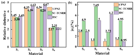
Figure 9: The results of elliptically doped CPNZ media sensor, SC-TCSRR sensor and IDC sensor relative permittivity relative error.
In the same frequency band, Fig. 9 shows that the relative permittivity errors for the elliptically doped CPNZ media sensor remain below 2.8%, with an average relative error of 1.55%, while the errors for the SC-TCSRR sensor are below 7.7%, with an average relative error of 5.055%. The relative permittivity error of the IDC sensor remains below 6.2%, with an average relative error of 3.737%. The relative permittivity measurement accuracy of the elliptically doped CPNZ media sensor is better than that of other sensors, even when the material is bent. This confirms the high accuracy of the elliptically doped CPNZ media sensor in measuring ultra-thin surface coatings.
In addition to coating thickness and relative permittivity, which are crucial for material structure design and evaluation, the loss tangent is another important factor. However, most existing work does not thoroughly analyze the influence of material thickness, relative permittivity, and loss tangent on sensor transmission amplitude. Instead, it typically examines the relationship between relative permittivity, loss tangent, and sensor transmission amplitude, without considering the impact of thickness. Since thickness also affects the properties of materials, this simplified analysis compromises the accuracy of electromagnetic property measurements of their electromagnetic properties. Therefore, this paper analyzes the relationship among material thickness, relative permittivity, loss tangent, and sensor transmission amplitude.
First, the coating thickness, relative permittivity, and loss tangent were set. When the thickness increased from 0.5 mm to 1.5 mm in steps of 0.1 mm, the relative permittivity increased from 6 to 11 in steps of 0.5, and the loss tangent increased from 0 to 1.2 in steps of 0.1. A total of 1573 sets of data were obtained. The coating thickness, relative permittivity, and loss tangent were set as independent variables, with the transmission amplitude of the sensor as the dependent variable. The relationship between coating thickness, relative permittivity, loss tangent, and transmission amplitude was obtained through polynomial regression model fitting. As shown in Fig. 10, with a coefficient of determination of 0.9965.
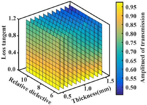
Figure 10: Relationship between thickness of absorbing coating, relative permittivity, loss tangent, and transmission amplitude.
In practical applications, the complex permittivity of most absorbing coatings is known, while the thickness is unknown. The absorbing properties of coatings with different thicknesses also vary. Therefore, five types of absorbing coatings with unknown thickness and known complex permittivity were selected as measurement objects. The five coatings are Al doped Ti3SiC2/paraffin wax, Ti3SiC2/paraffin, 12% CB/MAS, 4%CB/MAS, and 7% MWCNTs/MAS. The thicknesses of these five coatings, denoted as X, X, X, X, and X, were predicted. The thickness range of the five coatings was set to increase from 0.5 mm to 1.5 mm in steps of 0.1 mm. A total of 55 sets of data were obtained. The obtained polynomial was used to invert the 55 sets of data from the simulation, and the relative errors of the five coatings at different thicknesses were compared to determine the most likely thickness. The thickness prediction values and relative errors obtained from the inversion are shown in Table 4. It can be seen that the relative thickness error for the five coatings is less than 1.1%, indicating good predictability.
Table 4: Thickness prediction and relative error of absorbing coatings with different complex permittivity
| MUT | tan | Predicted Thickness (c) | |e| | |
| X | 5.94 | 0.0724 | 1.2 mm | 0.17% |
| X | 8.42 | 0.641 | 1 mm | 1% |
| X | 9.10 | 0.297 | 0.8 mm | 0.04% |
| X | 9.54 | 0.521 | 0.9 mm | 1.1% |
| X | 10.70 | 1.21 | 1.1 mm | 0.06% |
III. DISCUSSION
We have proposed a promising CPNZ sensor for ultra-thin coating materials measurement. We will fabricate and experimentally validate the sensors and to discuss the effects of fabrication and measurement tolerances on the sensing performance. In our work, it is assumed that the temperature and humidity are controlled within a small range of variations. The CPNZ sensor can be used in conjunction with an on-site reflectance measurement system. First, a suitable CPNZ sensor structure is modeled based on the curved surface geometry of the practical equipment under test. The reflectivity of the ultra-thin microwave-absorbing coating on the equipment is measured, and its complex permittivity can be inverted. By using the first inversion approach, inversion thickness with known relative permittivity, we can obtain the thickness of the microwave-absorbing coating. On the other side, if we have measured the thickness of the ultra-thin microwave-absorbing coating by using a thickness gauge, we can obtain the complex permittivity by using the second inversion approach, inversion of relative permittivity with known thickness. Additionally, for multi-physical-field detection, the CPNZ sensor could be extended by incorporating environmental sensing capabilities such as temperature and humidity sensors to construct a composite sensing platform. This would enable simultaneous acquisition of dielectric properties, coating thickness, and environmental conditions in complex operating environments.
IV. CONCLUSION
The proposed high-precision CPNZ medium microwave sensor offers a significant advancement for measuring the complex permittivity and thickness of ultra-thin surface materials. It overcomes the limitations of traditional sensors, which struggle with measuring the complex permittivity of curved materials and provides an effective solution for material thickness measurement. Simulation results demonstrate that the elliptically doped CPNZ media sensor outperforms other sensors in accurately measuring the complex permittivity of ultra-thin surface materials. The detection limit for thickness is 0.5 mm, with a measurement accuracy of up to 97% for relative permittivity. This sensor is capable of accurately measuring the complex permittivity of absorbing coatings of varying thicknesses and can predict the thickness of different types of absorbing coatings. It is expected to be an ideal choice for applications involving curved surface materials.
ACKNOWLEDGMENT
This work is supported by the National Natural Science Foundation of China under Grant No. 61971469 and Fundamental Research Funds of Shaanxi Key Laboratory of Artificially-Structured Functional Materials and Devices (AFMD-KFJJ-24212).
REFERENCES
[1] X. Weng, B. Li, Y. Zhang, X. Lv, and G. Gu, “Synthesis of flake shaped carbonyl iron/reduced graphene oxide/polyvinyl pyrrolidone ternary nanocomposites and their microwave absorbing properties,” Journal of Alloys and Compounds, vol. 695, pp. 508-519, 2017.
[2] Z. Li, X. Wei, F. Luo, W. Zhou, and Y. Hao, “Microwave dielectric properties of Ti3SiC2 synthesized by solid state reaction,” Ceramics International, vol. 40, pp. 2545-2549, 2014.
[3] J. Su, W. Zhou, Y. Liu, Y. Qing, F. Luo, and D. Zhu, “Effect of carbon black on dielectric and microwave absorption properties of carbon black/cordierite plasma-sprayed coatings,” Journal of Thermal Spray Technology, vol. 24, pp. 826-835, 2015.
[4] J. Su, W. Zhou, Y. Liu, Y. Qing, F. Luo, and D. Zhu, “Atmosphere plasma-sprayed carbon nanotubes/cordierite nanocomposite coatings for microwave absorption applications,” Journal of Thermal Spray Technology, vol. 23, pp. 1065-1072, 2014.
[5] F. Horner, T. A. Taylor, R. Dunsmuir, J. Lamb, and W. Jackson, “Resonance methods of dielectric measurement at centimetre wavelengths,” Electrical Engineers Part III: Radio and Communication Engineering, vol. 93, no. 21, pp. 53-68, 1946.
[6] M. Santra and K. U. Limaye, “Estimation of complex permittivity of arbitrary shape and size dielectric samples using cavity measurement technique at microwave frequencies,” IEEE Transactions on Microwave Theory and Techniques, vol. 53, no. 2, pp. 718-722, 2005.
[7] H. Miyagawa, K. Wakino, Y. D. Lin, and T. Kitazawa, “Simultaneous determination of complex permittivity and permeability of columnar materials with arbitrarily shaped cross section,” IEEE Transactions on Microwave Theory and Techniques, vol. 57, no. 9, pp. 2249-2256, 2009.
[8] A. Yasin, F. Rehman, U. Naeem, S. A. Khan, and M. F. Shafique, “Top loaded TM01 mode cylindrical dielectric resonator for complex permittivity characterization of liquids,” Radio Engineering, vol. 25, no. 4, pp. 714-720, 2016.
[9] M. Saadat-Safa, V. Nayyeri, M. Khanjarian, M. Soleimani, and O. M. Ramahi, “A CSRR-based sensor for full characterization of magneto-dielectric materials,” IEEE Transactions on Microwave Theory and Techniques, vol. 67, no. 2, pp. 806-814, 2019.
[10] R. Moolat, M. Mani, S. V. Abdulrahiman, A. Pradeep, V. Kesavath, and M. Pezholil, “Liquid permittivity sensing using planar open stub resonator,” Journal of Electronic Materials, vol. 49, no. 3, pp. 2110-2117, 2020.
[11] C. L. Yang, C. S. Lee, K. W. Chen, and K. Z. Chen, “Noncontact measurement of complex permittivity and thickness by using planar resonators,” IEEE Transactions on Microwave Theory Techniques, vol. 64, no. 1, pp. 247-257, 2016.
[12] J. K. Pakkathillam, B. T. Sivaprakasam, J. Poojali, C. V. Krishnamurthy, and K. Arunachalam, “Tailoring antenna focal plane characteristics for a compact free-space microwave complex dielectric permittivity measurement setup,” IEEE Transactions on Instrumentation and Measurement, vol. 70, pp. 1-12, 2021.
[13] Y. Xiang, J. Huang, L. Fu, Y. Chen, W. Gu, and Y. Wu, “A folded substrate integrated waveguide re-entrant cavity for full characterization of magneto-dielectric powder materials,” IEEE Sensors Journal, vol. 21, no. 9, pp. 10657-10666, 2021.
[14] C. Wang, X. Liu, L. Gan, and Q. Cai, “A dual-band non-destructive dielectric measurement sensor based on complementary split-ring resonator,” Frontiers in Physics, vol. 9, p. 669707, 2021.
[15] Z. Abbasi, P. Shariaty, M. Nosrati, Z. Hashisho, and M. Daneshmand, “Dual-band microwave circuits for selective binary gas sensing system,” IEEE Transactions on Microwave Theory and Techniques, vol. 67, no. 10, pp. 4206-4219, Oct.2019.
[16] N. Javanbakht, G. Xiao, and R. E. Amaya, “Portable microwave sensor based on frequency-selective surface for grain moisture content monitoring,” IEEE Sensors Letters, vol. 5, no. 11, pp. 1-4, 2021.
[17] Y. Cao, K. Chen, C. Ruan, and X. Zhang, “Robust and sensitive metamaterial-inspired microfluidic sensor for liquids with low dielectric constants,” Sensors and Actuators A-Physical, vol. 331, p. 112869, 2021.
[18] E. Rahamim, D. Rotshild, and A. Abramovich, “Performance enhancement of reconfigurable metamaterial reflector antenna by decreasing the absorption of the reflected beam,” Applied Sciences-Basel, vol. 11, p. 8999, 2021.
[19] W. Zhou, Z. Zhu, and R. Bai, “Low-frequency broadband lightweight magnetic composite absorber based on metamaterial structure,” OPTIK, vol. 244, p. 167619, 2021.
[20] A. K. Jha and M. J. Akhtar, “Elevated and tapered microstrip coupled ENZ SIW sensor for microwave testing of radome and building materials in 3G and ISM bands,” in URSI Asia-Pacific Radio Science Conference (URSI AP-RASC), Seoul, Korea (South), pp. 1761-1764, 21-25 Aug. 2016.
[21] Z. Zhou, Y. Li, H. Li, W. Sun, I. Liberal, and N. Engheta, “Substrate-integrated photonic doping for near-zero-index devices,” Nature Communications, vol. 10, no. 1, p. 4132, 2019.
[22] H. Lobato-Morales, A. Corona-Chávez, J. L. Olvera-Cervantes, R. A. Chávez-Pérez, and J. L. Medina-Monroy, “Wireless sensing of complex dielectric permittivity of liquids based on the RFID,” IEEE Transactions on Microwave Theory and Techniques, vol. 62, no. 9, pp. 2160-2167, 2014.
[23] A. K. Jha, N. Delmonte, A. Lamecki, M. Mrozowski, and M. Bozzi, “Novel MNZ-type microwave sensor for testing magnetodielectric materials,” Scientific Reports, vol. 10, no. 1, pp. 1-3, 2020.
[24] S. Mário and E. Nader, “Tunneling of electromagnetic energy through subwavelength channels and bends using epsilon-near-zero materials,” Physical Review Letters, vol. 97, p. 157403, 2006.
[25] V. Pacheco-Peña, M. Beruete, P. Rodríguez-Ulibarri, and N. Engheta, “On the performance of an ENZ-based sensor using transmission line theory and effective medium approach,” New Journal of Physics, vol. 21, no. 4, p. 043056, 2019.
[26] L. Ali, C. Wang, F. Y. Meng, K. K. Adhikari, Y. C. Wei, J. H. Li, Z. W. Song, and M. Zhao, “Design and optimization of interdigitated microwave sensor for multidimensional sensitive characterization of solid materials,” IEEE Sensors Journal, vol. 21, no. 20, pp. 22814-22822, 2021.
BIOGRAPHIES

Si Hui Jia is currently pursuing the doctor’s degree in Electronic Science and Technology at Shanghai University, Shanghai 200444, China. He received the master’s degree in electronics and communication engineering from Yangtze University, Jingzhou 434023, China, in 2022. His current research is in the direction of microwave sensing.

Yu Wei Mao received the B.S. degree from Bengbu College, Bengbu, China, in 2015, and the master’s degree in Communication and Information Engineering at Shanghai University, Shanghai 200444, China, in 2018. Her current research is focused on near-zero medium sensor technology.
Qiao Yu Li is currently pursuing the doctor’s degree in Electromagnetic Field and Microwave Technology in Shanghai University, Shanghai 200444, China. She received the B.S. degree in Engineering from Henan Normal University, Xinxiang, China, in 2016, received the master’s degree in Electromagnetic Field and Microwave Technology from Shanghai University, Shanghai 200444, China, in 2019. Her current research is focused on plasmonic sensor devices.

Zi Jian Gao was born in Tongcheng, Anhui Province, China, in 1998. Currently, he is pursuing a master’s degree in communication and information systems at Shanghai University, China, and his research interests are microwave sensing and algorithms.
Yong Jin Zhou received the B.S. degree in communication engineering from Shandong University, Jinan, China, in 2006, and Ph.D. degree in electromagnetic field and microwave technology from Southeast University, Nanjing, China, in 2011. From 2009 to 2010, he was a visiting scholar of University of Houston. From 2011 to 2012, he was a software engineer with EEBU of Marvell Technology (Shanghai) Ltd. From 2012 to 2015, he was an Assistant Professor with School of Communication & Information Engineering, Shanghai University, Shanghai, China. From 2015, he was an Associate Professor with School of Communication & Information Engineering, Shanghai University, Shanghai, China. From 2020, he was a Professor with School of Communication & Information Engineering, Shanghai University, Shanghai, China. His current research interests include plasmonic metamaterials, millimeter wave and THz functional devices, wireless energy transmission, and computational electromagnetism. He has served as Applied Computational Electromagnetics Society (ACES) Journal guest editor and is serving as a Youth Editorial Board Member Journal of Electronics & Information Technology . He is serving as a Reviewer for over 20 peer-reviewed journals, such as Nature Electronics, Photonic Research, Optics Letter, Optics Express, Appl. Phys. Express, IEEE Access, IEEE MTT, and IEEE MWCL . He has served as a session chair for several International Symposiums.
ACES JOURNAL, Vol. 40, No. 6, 525–533
doi: 10.13052/2024.ACES.J.400605
© 2025 River Publishers