Investigations on the Influence of Augmented Rail Geometry on Rail Gun Design Parameters using Finite Element Method
M. N. Saravana Kumar, R. Murugan, J. Lydia, and S. Leones Sherwin Vimalraj
1Department of Electronics and Communication Engineering
Kings Engineering College, Chennai, Tamil Nadu, India
dr.mnskphd@gmail.com
2Department of Electrical and Electronics Engineering
Bharath Institute of Higher Education and Research, Chennai, Tamil Nadu, India
ramumurugan_r@rediffmail.com
3Department of Electrical and Electronics Engineering
Easwari Engineering College, Chennai, Tamil Nadu, India
lydia.jeec@gmail.com
4Department of Electronics and Communication Engineering
Panimalar Engineering College, Chennai, Tamil Nadu, India
sherwin_leo@yahoo.com
Submitted On: March 6, 2025; Accepted On: May 23, 2025
ABSTRACT
This paper investigates the effect of augmented rail geometry on rail gun key parameters such as mutual inductance gradient between the main and augmented rail (M’), maximum current density, and maximum magnetic flux density distribution in the rail cross-section, as well as repulsive force acting on the rails. The research study was conducted using a rectangular main rail with several augmented rail designs, including rectangular T, rectangular E, rectangular U, rectangular Convex, and rectangular Concave under inward and outward modes. The ANSYS MAXWELL 2-D eddy current field solver, which computes the magnetic field distributions for a given configuration using the finite element method, was used to calculate the rail gun essential parameters. Using the obtained results, a comparison study was conducted. It was found that the rectangular main rail with the inward circular convex augmented form rail cross-section had a greater value of M’ than other geometries; hence, it could be utilized to increase the armature’s velocity.
Index Terms: Current density, magnetic flux density, mutual inductance, repulsive force, velocity.
I. INTRODUCTION
One weapon technology that can be utilized to increase the projectile’s velocity is the rail gun [1]. In order to accelerate the projectile with a faster velocity, the rail gun must overcome numerous obstacles and hurdles during design and construction [2]. Getting a greater electromagnetic force on a projectile to increase its acceleration and velocity is one of the primary issues in rail gun design.One of the traditional ways to increase force on the armature is to typically excite the rails with a high current magnitude for a brief period of time. This results in an uneven current density distribution in the rail and armature, which damages the rail and armature because it increases local heat and erosion in therails [3].
Increasing the inductance gradient of the rails is another method of increasing the projectile’s acceleration in a traditional rail cannon. This is a crucial element in rail gun design because it directly affects the force applied on the projectile [4, 5].
The dimensions, shape, and material properties of the rail all affect the inductance gradient values. Using analytical and computational techniques, numerous researchers have proposed different rail shapes in the past year to raise the inductance gradient value of the rails [6–12]. Researchers discovered that attaining a uniform current density distribution in the rail is the primary challenge in rail gun design. Therefore, without reducing the armature force with uniform current density distribution the researchers followed one of the advanced techniques is the augmented rail gun, as seen in Fig. 1, which involves connecting extra rails to the main rails either in series or parallel to create an additional magnetic field between them. This lowers the current flowing to the rail and helps to accelerate the projectile with a highervelocity [13].
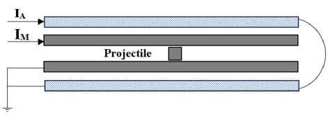
Figure 1: Basic rectangular augmented rail gun [14].
The railgun Lorentz force is determined by
| (1) |
For an improved rail gun, the electromagnetic force operating on the armature is [15]
| (2) |
where I is the current flowing through the augmenting rail, M’ is the mutual inductance gradient between the main rail and the augmenting rail, I is the electrical current flowing through the main rail, F is the armature’s accelerating force, and L’ is the main rail’s inductance gradient. The force acting on the armature is directly proportional to the L’ and M’, according to the equation. Since the M’ value is dependent on the dimensions and shape of the main and augmented rail, research has been conducted in recent years to raise the M’ value by altering these elements. Simulation and experimentation have been used in recent years to improve the performance of augmented rail [14–23].
This study uses the ANSYS MAXWELL 2-D finite element method to analyze the impact of augmented rail geometries’ shape on rail gun key design parameters like L’ and M’, the main rails’ maximum current density distribution (J) and magnetic flux density distribution (B), and the repulsive force acting on the main rails (F) and augmented rails (F).
II. GOVERNING EQUATIONS FOR RAILGUN DESIGN PARAMETER CALCULATION
When the displacement current is ignored, and Maxwell’s equations are used to calculate the electric and magnetic fields [24–26], we have
| (3) | ||
| (4) | ||
| (5) | ||
| (6) | ||
| (7) |
Additionally, in the transitory case, the differential equation for the magnetic vector potential is:
The magnetic flux density, permeability, conductivity, and impressed current density are denoted by , , , and J, respectively. The following is the induced eddy current:
| (10) |
For the 2-D situation, equation (8) reduces to
| (11) |
This formula can be used in any 2-D time-varying scenario that involves non-linear magnetic materials. If J is a time harmonic excitation with frequency (rad/s), then (10) can be expressed as follows by substituting j for
| (12) |
Solving this equation yields magnetic vector potential (A). B may be derived from (8). The magnetic energy per length is then determined using
| (13) |
This is the force exerted to the armature and may be expressed as
| (14) |
where i is the element index and S is the area of the i element. The inductance gradient L’ is defined as the ratio of magnetic energy per length to current squared. Then, using equations (14) and (1), we may write:
| (15) |
the equation we used to calculate the inductance gradient, L.
III. THE EFFECT OF AUGMENTED RAIL GEOMETRY ON RAIL GUN DESIGN PARAMETERS
A. Validation of basic rectangular augmented rail gun
To examine the effect of augmented rail geometry form on rail gun design parameters, the ANSYS Maxwell is first validated by simulating the 2-D basic rectangular augmented rail gun as shown in Fig. 2.
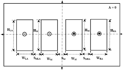
Figure 2: A simple rectangular enhanced rail gun.
The main rails (MR) and augmented rails (AR) are assumed to supply a current of 250 kA with a maximum frequency of 2000 Hz. In Fig. 2 the cross indicates the current supplied to the rail is passes into the rail and the dot indicates the current comes out of the rails. The main rail height (H), width (W), and rail separation (S) are assumed to be 15 mm, 30 mm, and 10 mm, respectively. The height and width of the left- and right-hand augmented rails (H and W, H and W) are considered to be 30 mm and 15 mm, respectively. The spacing between the main rail and the left and right augmented rails (SM and SM) is expected to be 10 mm. The main and supplemental rails are supposed to be copper with a conductivity of 5.810 S. The magnetic vector potential (A) at the external border is taken to be zero.The rail geometry is symmetrical about the X and Y axes; therefore one-fourth of the rail structure might be utilized to imitate the rail cannon. In this study, the rail construction is mimicked without using the symmetrical characteristic. The enlarged rail gun geometry is simulated with ANSYS Maxwell, and the inductance gradient L’ and mutual inductance M’ are measured to be 0.492 H/m and 0.225 H/m, respectively. These values are consistent with the findings [14].
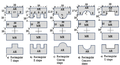
Figure 3: Different types of augmented inward rail geometries.
B. Augmented rail geometry’s impact on various configurations
Several rails augmented geometry designs, including the rectangular T, E, Convex, Concave, and U shapes shown in Figs. 3 and 4, were considered and simulated in order to assess their impact in this study. The augmented geometry always has an area of 450 mm, which is equivalent to the area of a rectangular augmented rail. The dimensions of the rails, for each rail configuration are in millimeter (mm) which is given in the Fig. 3 and in order to get the constant cross-sectional area of augmented rail geometry the width of the rail is adjusted.
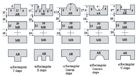
Figure 4: Different types of augmented outward rail geometries.
IV. SIMULATION RESULTS
Figures 5 and 6 demonstrate the current density distribution over rail cross-sections generated from simulations for various shapes of augmented rail geometry. Due to the symmetrical structure of the rail geometry, only the upper portion is represented in the illustrations.
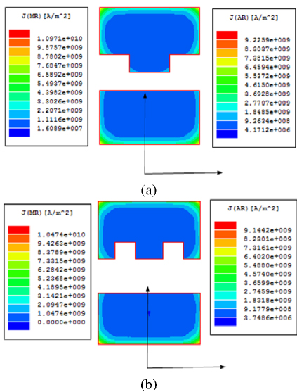
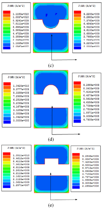
Figure 5: Current density distribution over different inwards augmented rail geometries: (a) rectangular T shape, (b) rectangular E shape, (c) rectangular Convex shape, (d) rectangular Concave shape, and (e) rectangular U shape.
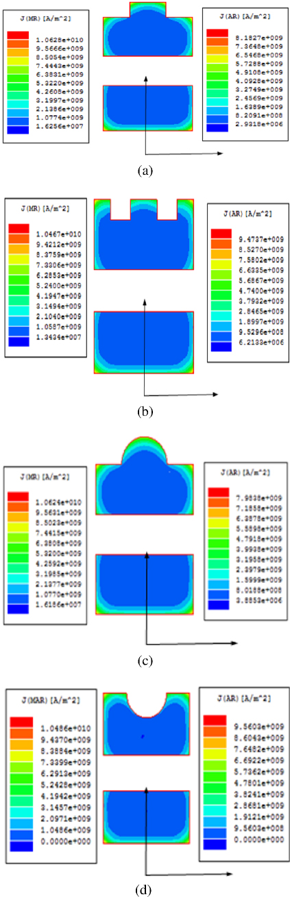
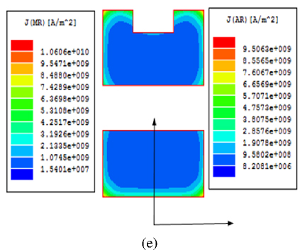
Figure 6: Current density distribution over different outwards augmented rail geometries: (a) rectangular T shape, (b) rectangular E shape, (c) rectangular Convex shape, (d) rectangular Concave shape, and (e) rectangular U shape.
Figures 5 and 6 show that the current density distribution in the rail is not uniform, with the majority of the current distributed nearer to the surface of the conductors, known as the skin effect. It is also discovered that the current density distribution is highest at the inside surface edges of the main rail and the outer surface edges of the enhanced rail.This results in substantial ohmic losses at the surface of the rail cross-section, as well as non-uniform temperature distribution in the rail, which causes damage. This can be adjusted by adjusting the current provided to enhanced rails. Tables 1 and 2 demonstrate the rail gun essential design characteristics acquired from simulations for various rail augmented rail geometries under inward and outward situations.
Table 1: Rail gun key design characteristics for various inwardly enhanced rail cross-sections
| Augmented Rail Shape | L’(H/m) | M’(H/m) | J(A/m) | J(A/m) | B(Tesla) | B(Tesla) | F& F(kN) |
| Rectangular | 0.492 | 0.225 | 1.065 | 9.236 | 9.12 | 7.84 | 110.9 |
| T | 0.492 | 0.256 | 1.097 | 9.226 | 9.40 | 7.78 | 132.02 |
| E | 0.492 | 0.218 | 1.047 | 9.144 | 9.04 | 7.89 | 97.64 |
| Convex | 0.492 | 0.263 | 1.115 | 9.22 | 9.97 | 7.92 | 142.7 |
| Concave | 0.492 | 0.207 | 1.042 | 9.266 | 9.26 | 8.23 | 84.03 |
| U | 0.492 | 0.215 | 1.05 | 9.284 | 9.00 | 8.02 | 93.01 |
Table 2: Rail gun key design characteristics for various outwardly expanded rail cross-sections
| Augmented Rail Shape | L’(H/m) | M’(H/m) | J(A/m) | J(A/m) | B(Tesla) | B(Tesla) | F& F(kN) |
| Rectangular | 0.492 | 0.225 | 1.065 | 9.236 | 9.12 | 7.84 | 110.9 |
| T | 0.492 | 0.221 | 1.063 | 8.183 | 9.13 | 7.08 | 105.3 |
| E | 0.492 | 0.214 | 1.047 | 9.474 | 8.98 | 8.18 | 92.05 |
| Convex | 0.492 | 0.223 | 1.07 | 7.98 | 9.15 | 7.35 | 103.3 |
| Concave | 0.492 | 0.213 | 1.04 | 9.56 | 9.34 | 8.5 | 90.8 |
| U | 0.492 | 0.217 | 1.06 | 9.50 | 9.11 | 8.05 | 105 |
Tables 1 and 2 show that adding augmented rail and modifying the shape of its cross-section has no effect on the value of the main rail’s inductance gradient, whereas other rail gun critical design parameters are altered by the augmented rail shape change. Table 1 shows that M’ values are higher for the rectangular T and Convex augmented rail geometries. This may be due to the rail bulging inwards which decreases the separation between the main and augmented rail. The rectangular Convex augmented rail geometry has a high mutual inductance (0.263 H/m) compared to other structures. However, the current density and magnetic flux density distribution over the rail cross-section, as well as the repulsive force acting on the rails, are higher. It is also observed that the repulsive force acting on the main rail and enhanced rail is the same for each rail cross-section, indicating that the repulsive force operating on the rail is primarily determined by the current flowing through the rails rather than the distance between the rails.Tables 1 and 2 show that M’ values are lower for all configurations when compared to the basic rectangular augmented rail geometry in the outward mode. As a result, the rectangular Convex enhanced rail geometry in inward mode might be used to increase the armature’svelocity.
V. CONCLUSION
This research investigates the effect of modifying the form of an augmented rail cross-section on rail gun critical design parameters using the finite element approach. Rail gun essential design characteristics are estimated for several enhanced rail geometries, including rectangular T shape, rectangular E shape, rectangular U shape, rectangular Convex, and rectangular Concave, in both inward and outward modes. A detailed comparison analysis was performed utilizing the collected results, and it was discovered that the M’ value is higher in values for inward mode that enhanced the rail geometry when compared to outward mode. When compared to the standard rectangular augmented rail geometry, the rectangular T shape and rectangular Convex augmented rail geometries have greater M’ values. As a result, the rectangular Convex enhanced rail geometry in inward mode might be used to increase the armature’svelocity.
REFERENCES
[1] M. Asgari, M. B. Heydari, L. Gharib, A. Keshtkar, N. Jafari, and M. Zolfaghari, “A novel augmented railgun using permanent magnets,” Advanced Electromagnetics, vol. 8, pp. 99-105, 2019.
[2] M. B. Heydari, M. Asgari, and A. Keshtkar, “A novel structure of augmented railgun using multilayer magnets and sabots,” IEEE Transactions on Plasma Science, vol. 47, no. 7, pp. 3320-3325, July 2019.
[3] M. Putnam, “An experimental study of electromagnetic Lorentz force and rail recoil,” Naval Postgraduate School, Monterey, CA, USA, Tech. Rep. 0704-0188, 2009.
[4] R. Murugan and K. Udayakumar, “Effect of rail dimensions on rail gun design parameters,” in 2005 Annual IEEE India Conference - Indicon, pp. 623-626, 2005.
[5] A. Keshtkar, “Effect of rail dimension on current distribution and inductance gradient,” IEEE Trans. Magn., vol. 41, no. 1, pp. 383-386, Jan. 2005.
[6] M. S. Bayati and A. Keshtkar, “Study of the current distribution, magnetic field, and inductance gradient of rectangular and circular rail guns,” IEEE Trans. Plasma Sci., vol. 41, no. 5, pp. 1376-1381, May 2013.
[7] M. N. Saravana Kumar and R. Murugan, “Analysis of inductance gradient and current density distribution over different cross-section of rails,” International Journal of Electrical and Computer Engineering, vol. 8, pp. 723-729,2018.
[8] M. N. Saravana Kumar, R. Murugan, and S. Poorani, “Inductance gradient and current density distribution for T-shaped convex and concave rail cross-sections,” International Journal of Engineering & Technology (UAE), vol. 7, no. 01, pp. 237-240, 2018.
[9] J. Lydia, R. Karpagam, and R. Murugan, “A novel technique for dynamic analysis of an electromagnetic rail launcher using FEM coupled with Simplorer,” Applied Computational Electromagnetics Society (ACES) Journal, vol. 37, no. 2, pp. 229-237, Feb. 2022.
[10] M. S. Bayati and A. Keshtkar, ”Study of the current distribution, magnetic field, and inductance gradient of rectangular and circular railguns,” IEEE Transactions on Plasma Science, vol. 41, no. 5, pp. 1376-1381, May 2013.
[11] A. Keshtkar, L. Gharib, M. S. Bayati, and M. Abbasi, “Simulation of a two-turn railgun and comparison between a conventional railgun and a two-turn railgun by 3-D FEM,” IEEE Transactions on Plasma Science, vol. 41, no. 5, pp. 1392-1397, May 2013.
[12] M. S. Bayati and A. Keshtkar, ”Novel study of the rail’s geometry in the electromagnetic launcher,” IEEE Transactions on Plasma Science, vol. 43, no. 5, pp. 1652-1656, May 2015.
[13] A. Keshtkar, L. Gharib, M. S. Bayati, and M. Abbasi, “Simulation of a two-turn railgun and comparison between a conventional railgun and atwo-turnrailgunby3-DFEM,” IEEE Trans. Plasma Sci., vol. 41, no. 5, pp. 1392-1397, May 2013.
[14] J. Gallant, “Parametric study of an augmented railgun,” IEEE Transactions on Magnetics, vol. 39, pp. 451-455, 2003.
[15] J. Gallant and P. Lehmann, “Experiments with brush projectiles in a parallel augmented railgun,” IEEE Transactions on Magnetics, vol. 41, no. 1, pp. 188-193, Jan. 2005.
[16] Z. Su, W. Guo, Z. Dong, J. Yang, H. Zhang, and W. Zhou, “Design and simulation of a large muzzle kinetic energy railgun,” in 2012 16th International Symposium on Electromagnetic Launch Technology, Beijing, China, pp. 1-4, 2012.
[17] T. Watt and M. Crawford, “Experimental results from a two-turn 40 mm railgun,” in 2008 14th Symposium on Electromagnetic Launch Technology, Victoria, BC, Canada, pp. 1-6,2008.
[18] E. Poltanov, A. K. Kondratenko, A. P. Glinov, and V. N. Ryndin, “Multi-turn railguns: Concept analysis and experimental results,” IEEE Transactions on Magnetics, vol. 37, no. 1, pp. 457-461, Jan. 2001.
[19] M. Coffo and J. Gallant, “Modeling and analysis of the current distribution between the brushes of a multiple brush projectile in a parallel augmented railgun,” in 2008 IEEE International Power Modulators and High-Voltage Conference, Las Vegas, NV, USA, pp. 419-422, 2008.
[20] M. Coffo and J. Gallant, “Modelling of a parallel augmented railgun with Pspice validation of the model and optimization of the augmenting circuit,” in 2007 16th IEEE International Pulsed Power Conference, Albuquerque, NM, USA, pp. 1814-1817, 2007.
[21] S. Mozafari and M. S. Bayati, “Design and simulation of a slice-rail and cylindrical for multi-projectile electromagnetic launchers: electromagnetic,” Applied Computational Electromagnetics Society (ACES) Journal, vol. 38, no. 3, pp. 214-223, Mar. 2023.
[22] M. Roch, S. Hundertmark, M. Löffler, and P. Zacharias, “First experiment with the modular augmented staged electromagnetic launcher,” IEEE Transactions on Plasma Science, vol. 42, no. 10, pp. 3239-3244, Oct. 2014.
[23] M. Roch, S. Hundertmark, M. Löffler, and P. Zacharias, “Augmented electromagnetic accelerators: Technical solutions and new ideas,” IEEE Transactions on Plasma Science, vol. 41, no. 10, pp. 2810-2814, Oct. 2013.
[24] M. J. Loeffler and F. Zellmer, “Augmented three phase AC railgun: Basic considerations,” IEEE Transactions on Plasma Science, vol. 51, no. 1, pp. 249-253, Jan. 2023.
[25] A. Keshtkar, S. Bayati, and A. Keshtkar, ”Effect of rail’s material on railgun inductance gradient and losses,” in 2008 14th Symposium on Electromagnetic Launch Technology, pp. 1-4, 2008.
[26] K. Hsieh, “A Lagrangian formulation for mechanically, thermally coupled electromagnetic diffusive processes with moving conductors,” IEEE Transactions on Magnetics, vol. 31, no. 1, pp. 604-609, Jan. 1995.
BIOGRAPHIES

M. N. Saravana Kumar received a bachelor’s degree in Electronics and Communication Engineering from Bhajarang Engineering College, Chennai, India, in 2009. He received his master’s degree in Power electronics and drives from Rajalakshmi Engineering College, Chennai, India, in 2013, and Ph.D. degree in Electrical and Electronics Engineering department from St. Peter’s Institute of Higher Education and Research, Chennai, India, in 2019. His main areas of interest are power electronics and drives, electrical machine design, electromagnetic field computation and modelling.

R. Murugan received bachelor’s degree in Electrical and Electronics Engineering from University of Madras, Tamil Nadu, India, in April 1996. He received his master’s degree in High Voltage Engineering from College of Engineering, Anna University, Guindy, Chennai, Tamil Nadu, India, in February 1999, and Ph.D. degree in Electrical and Electronics Engineering department from Anna University, Chennai, Tamil Nadu, India, in 2011. His main areas of interest are electromagnetic field and high voltage engineering.

J. Lydiareceived the bachelor’s degree in Electrical and Electronics Engineering from Easwari Engineering College, Chennai, India, in 2004. She received master’s degree in Power Electronics and Drives from the Karunya Institute of Technology and Sciences, Deemed University, in 2006, and Ph.D. degree in Electrical Engineering from Anna University, Chennai, India, in 2024. She is currently working as an Assistant Professor in the Department of Electrical and Electronics Engineering, Easwari Engineering College. Her areas of interest are electromagnetic fields and high-voltage engineering. She is a member of MISTE.

S. Leones Sherwin Vimalraj is a Professor in the Department of Electronics and Communication Engineering, Panimalar Engineering College, Chennai, India. He completed his B.E. in Electronics and Communication Engineering from Karunya Institute of Technology, Bharathiar University, India, in 2001. He obtained his M.E. in Optical Communication Engineering (2004) from College of Engineering, Guindy, Anna University, and Ph.D. degree in Wireless Communication Engineering (2015) from Dr. MGR Educational and Research Institute, Deemed University, Chennai, India. His research areas include wireless communication, network engineering, computing and evolutionary algorithms. He is a member of IETE.
ACES JOURNAL, Vol. 40, No. 6, 564–570
doi: 10.13052/2024.ACES.J.400609
© 2025 River Publishers