Low-loss Miniaturized Tri-band Bandpass Filter with High Selectivity and Good Passband Symmetry
Chuan Shao
1School of Information Engineering
Jiangsu College of Engineering and Technology, Nantong Jiangsu 226000, P. R. China
ch_shao@126.com
2Jiangsu College of Engineering and Technology
Nantong Key Laboratory of Artificial Intelligence New Quality Technology, Nantong Jiangsu 226000, P. R. China
Submitted On: March 07, 2025; Accepted On: June 29, 2025
ABSTRACT
This paper introduces a low-loss microstrip line tri-band bandpass filter, utilizing quarter-wavelength (/4) tri-section stepped impedance resonators (TSSIRs). In this design, the adoption of a non-edge-coupled structure effectively eliminates the presence of coupling gaps. As a result, additional radiation losses are avoided, leading to lower insertion loss. In addition, the operating frequencies of the three passbands can be flexibly adjusted by tuning the impedance ratios in the TSSIR. Moreover, the /4 TSSIR exhibits a smaller size compared to existing /2 TSSIRs, resulting in a more compact overall design. In order to validate the proposed design methodology, a tri-band bandpass filter with passbands centered at 1.0 GHz, 3.5 GHz, and 6.0 GHz was designed, fabricated, and measured. The minimum insertion losses for each passband were measured to be 0.07 dB, 0.52 dB, and 1.14 dB, respectively. The filter occupies a compact area of 3121.5 mm2 (0.170.12), demonstrating excellent passband symmetry for each frequency band. The proposed tri-band bandpass filter not only achieves three desirable operating frequencies but also benefits from the inherent characteristics of conventional filters, such as remarkably low insertion loss and good passband symmetry.
Index Terms: Bandpass filters, high selectivity, low-loss feature, passband symmetry, TSSIRs.
I. INTRODUCTION
In recent years, multiband and multi-standard wireless communication systems have garnered significant attention due to their ability to support diverse communication standards and frequency bands [1]–[3]. Multiband bandpass filters are essential passive components in these systems, significantly influencing overall performance. Consequently, extensive research has been conducted to develop various design approaches for multiband bandpass filters. Traditional tri-band bandpass filters have been realized using three sets of resonators with common feeds [4]. However, these designs often suffer from large footprints due to the extensive use of resonators. To address this issue, alternative methods have been proposed, such as employing two sets of resonators where one set operates at two frequencies [5]–[6]. Another approach involves half-wavelength tri-section stepped impedance resonators (/2 TSSIRs, is the guided wavelength at the center frequency of the first passband) and other multi-mode resonators which can achieve tri-band functionality with only one set of resonators. Despite these innovations, /2 TSSIRs and multi-mode resonators still occupy a relatively large area [7]–[11]. Additionally, since the aforementioned filters all employ an edge-coupled structure, the coupling gaps are prone to generating certain levels of radiation. This radiation effect inevitably leads to relatively high insertion losses in these structures. Substrate integrated waveguide (SIW) has emerged as a widely adopted low-loss transmission line in recent years [12]–[14]. Owing to the confinement of microwave signals predominantly within the dielectric medium, microwave devices designed based on SIW exhibit inherently low insertion loss and are well-suited for operation at higher frequencies.
This paper presents a novel tri-band bandpass filter based on (/4) TSSIRs. The design process is both simple and effective. Conventional /4 uniform impedance resonators, while offering excellent performance, are limited by providing periodic center frequencies for the passbands. By replacing these /4 uniform impedance resonators with /4 TSSIRs, three distinct passbands can be readily achieved. The proposed filter exhibits a compact size, remarkably low insertion loss, and excellent passband symmetry.
Additionally, four inherent transmission zeros within the operational band significantly enhance selectivity and isolation between the three passbands.
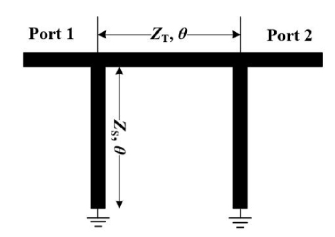
Figure 1: Transmission line bandpass filter with quarter-wavelength short-circuited stubs.
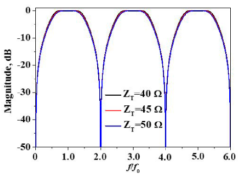
Figure 2: Simulated transmission coefficients of the structure shown in Fig. 1 with different values of ZT(Z).
II. ANALYSIS OF TRADITIONAL STUB BANDPASS FILTERS
Traditional stub bandpass filters can be configured in the form illustrated in Fig. 1, which consists of shunt-connected, short-circuited stubs each with an electrical length of and a characteristic impedance of ZS, coupled via connecting lines of an electrical length of and characteristic impedance of ZT. This particular arrangement leverages the quarter-wavelength resonance principle to achieve selective frequency transmission, effectively attenuating signals outside the designated passband while allowing those within the passband to propagate with minimal loss. Ideal transmission coefficients of the structure shown in Fig. 1 are given in Fig. 2. As depicted in Fig. 2, the stub bandpass filter is designed to exhibit three distinct passbands centered at f0, 3f0, and 5f0. These passbands correspond to the first three resonant frequencies of the /4 uniform impedance resonators employed in the filter design. Additionally, the filter inherently generates four transmission zeros located at DC, 2f0, 4f0, and 6f0, respectively. These transmission zeros play a crucial role in enhancing the filter’s performance by providing sharp transitions between passbands and stopbands. Consequently, the stub bandpass filter demonstrates superior performance in terms of band-to-band isolation and selectivity. Specifically, the presence of multiple transmission zeros ensures that the filter can effectively attenuate signals outside the desired passbands, thereby minimizing interference and crosstalk between adjacent bands. Simulated transmission coefficients of the structure shown in Fig. 1 with different values of ZS are illustrated Fig. 3. As illustrated in Figs. 2 and 3, the transmission characteristics of the stub bandpass filter demonstrate significant stability in response to variations in ZT. Specifically, when ZS is held constant, the transmission coefficients of the filter remain remarkably consistent, irrespective of fluctuations in ZT. This indicates that the filter’s performance is relatively insensitive to changes in ZT under constant ZS conditions. Furthermore, when ZT is kept constant, the transmission coefficients of the filter are observed to gradually decrease as the value of ZS increases. This suggests that the filter’s transmission efficiency is inversely related to the magnitude of ZS when ZT is maintained at a constant level.
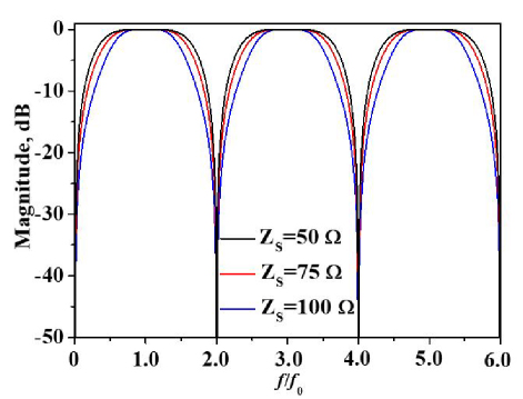
Figure 3: Simulated transmission coefficients of the structure shown in Fig. 1 with different values of ZS(ZT=50 ).
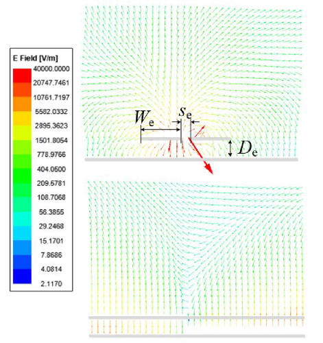
Figure 4: Electric field distribution on the cross-section of 50-ohm microstrip transmission lines and edge-coupled microstrip lines at 1 GHz (W1.9 mm, s0.2 mm, D0.813 mm).
It is worth highlighting that, in contrast to conventional edge-coupled bandpass filters, where bandwidth adjustment is predominantly achieved by varying the widths of the coupling gap, the developed stub bandpass filter exhibits a distinct feature. Specifically, it modulates its bandwidth by altering the impedance characteristics of the resonator. This unique approach circumvents the potential for spurious losses that typically arise from radiation in the coupling gap of traditional designs. To provide empirical evidence supporting this claim, Fig. 4 illustrates the electric field distributions within the cross-sections of both a 50-ohm microstrip transmission line and a 50-ohm coupled transmission line under analogous operating conditions. The electric field distributions of the aforementioned structures were obtained using the relevant functionalities in Ansys HFSS [18]. For both types of structures, namely the 50-ohm microstrip transmission lines and the edge-coupled microstrip lines, the electric field distributions were obtained at an operating frequency of 1 GHz. Upon examination of Fig. 4, it is evident that, when scaled identically, the coupled transmission line exhibits a more pronounced radiation of energy into the surrounding free space. This heightened radiation propensity is inherently associated with increased energy dissipation, thereby resulting in a comparatively higher insertion loss for the entire device. This observation underscores the significance of the design approach adopted in the stub bandpass filter, which effectively mitigates such spurious radiation losses by eschewing reliance on coupling gap adjustments, leading to a more efficient signal transmission and reduced overall insertion loss.
III. DESIGN OF THE DEVELOPED TRI-BAND BANDPASS FILTER
A. Analysis of the /4 tri-section stepped impedance resonators (TSSIRs)
The employed /4 TSSIR depicted in Fig. 5 is designed with three distinct characteristic impedances, Z1, Z2, and Z3. For practical applications, it is advantageous to assume that each section has an equal electrical length. Under this assumption, the input impedances in Fig. 5 can be precisely derived through a series of mathematical transformations:
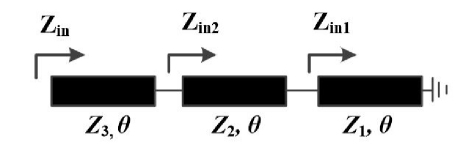
Figure 5: Structure of /4 TSSIR.
| (1) | ||
| (2) | ||
| (3) |
while the condition for the first three resonances of this TSSIR can be obtained as:
| (4) | ||
| (5) | ||
| (6) |
where KZ3/Z2, KZ2/Z1. When the discontinuity and dispersion effects of the TSSIR have been ignored, the fundamental property can be obtained as f: f: f: 02 : 03. Therefore, once center frequencies f1, f2, fhave been assigned, the required impedance ratios for the TSSIR can be determined using the same method as presented in [7].
The locations of transmission zeros of the developed bandpass filter can be determined by setting the input impedance Zin to zero. This provides the relationship:
| (7) |
Solving the above equation yields the following result:
| (8) | ||
| (9) | ||
| (10) |
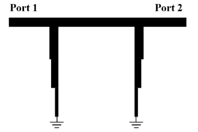
Figure 6: Proposed tri-band bandpass filter based on /4 TSSIRs.
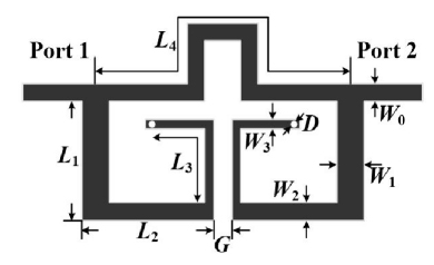
Figure 7: Layout of the developed tri-band bandpass filter based on /4 TSSIRs.
B. Tri-band bandpass filter design
Building upon the previous analysis of traditional stub bandpass filters and TSSIRs and drawing parallels to the design methodologies of conventional edge-coupled bandpass filters, the developed tri-band bandpass filter has been designed herein, as illustrated in Fig. 6. In order to minimize the impedance mismatch between the intermediate transmission line and the 50- ohm input/output, the characteristic impedance (ZT) of this transmission line between the two resonators was also selected to be 50 ohms.
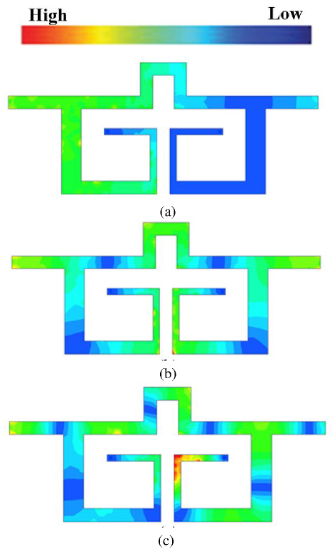
Figure 8: Current distributions at center frequencies of three passbands: (a) first passband (1 GHz), (b) second passband (3.5 GHz), (c) third passband (6 GHz).
In this design, the proposed tri-band bandpass filter prototype is designed on a Rogers 4003C substrate (3.55, tan0.0027) with a thickness of 0.813 mm. The center frequencies of the three passbands are 1 GHz, 3.5 GHz, and 6 GHz. Referring to the above theoretical analysis described in section II, the impedance ratios can be found to be K0.75 and K0.66. The width of the middle section of the proposed /4 TSSIR is selected as 2 mm, which corresponds to a characteristic impedance of 46 . The characteristic impedances of the other two sections are calculated to be Z70 and Z35 . Meanwhile, the electric length of each section at 1 GHz can be calculated as 25.7∘. Layout of the developed tri-band bandpass filter based on /4 TSSIRs is given in Fig. 7. For demonstration, current distributions at center frequencies of three passbands are shown in Fig. 8.
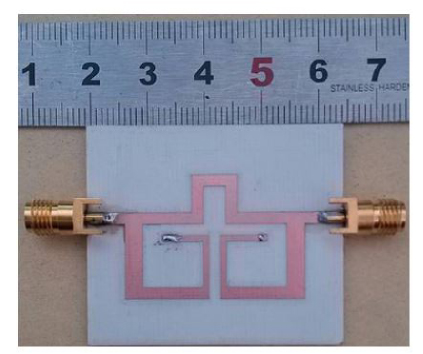
Figure 9: Photograph of the proposed tri-band bandpass filter (W1.9 mm, W3.05 mm, W2 mm, W1 mm, L13 mm, L14.5 mm, L14 mm, L41.2 mm, D0.6 mm, G2 mm).
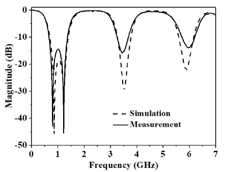
Figure 10: Simulated and measured reflection coefficients of the developed tri-band bandpass filter.
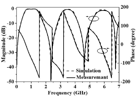
Figure 11: Simulated and measured transmission coefficients and phase of the developed tri-band bandpassfilter.
IV. RESULTS AND DISCUSSION
A photograph of the fabricated tri-band bandpass filter is depicted in Fig. 9, while the pertinent parameters of the tri-band filter are also provided. A comprehensive comparison between the simulated and measured results of the proposed tri-band bandpass filter is illustrated in Figs. 10 and 11. Additionally, the measured group delay of the filter is presented in Fig. 12. The filter exhibits three distinct passbands centered at 1 GHz, 3.5 GHz, and 6 GHz, respectively. Leveraging the aforementioned advantageous characteristics of the conventional filter structure, the measured minimum insertion losses of the three passbands are 0.07 dB, 0.52 dB, and 1.14 dB, respectively, inclusive of the losses attributed to the SMA connectors. Notably, the transmission zeros generated at 0 GHz, 2.35 GHz, 4.6 GHz, and 6.75 GHz have significantly enhanced the selectivity, passband symmetry, and band-to-band isolation of the proposed tri-band filter.
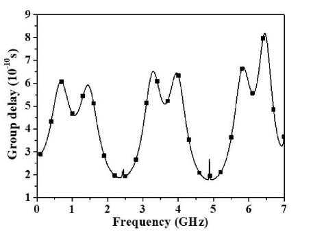
Figure 12: Measured group delay versus frequency for each passband.
Table 1: Calculated and measured locations of transmission zeros
| 1 | 2 | 3 | 4 | |
| Calculated Results | 0 GHz | 2.32 GHz | 4.69 GHz | 7.0 GHz |
| Measured Results | 0 GHz | 2.55 GHz | 4.45 GHz | 6.75 GHz |
Table 2: Comparison between proposed tri-band filter and prior works
| Ref. | f/ f/ f2GHz | Insertion LossesdB | FabricationProcess | Passband Symmetry Ratio | Sizeg |
| 4 | 2.5/3.5/5.7 | 1/1.2/1.5 | Microstripline | 1.6/1.06/1.18 | 0.260.2 |
| 5 | 1.84/2.45/2.98 | 0.9/1.6/0.8 | Microstripline | 1.1/1/14/1.5 | 0.270.2 |
| 6 | 1.8/3.5/5.8 | 0.88/1.33/1.77 | Microstripline | 1.1/1.04/1.52 | 0.520.11 |
| 7 | 1.57/2.45/3.5 | 0.77/1.51/1/8 | Microstripline | 1.13/1.14/1.2 | 0.230.16 |
| 8 | 1.0/2.4/2.6 | 2.0/1.9/1.7 | Microstripline | 1.7/1.07/1.06 | 0.20.2 |
| 9 | 1.64/3.04/4.8 | 1.54/1.71/2.4** | Microstripline | 1.14/1.18/1.75 | 0.240.2 |
| 10 | 3.16/4.27/5.70 | 1.6/2.5/2.9 | Microstripline | 1.1/1.05/1.64 | 0.590.19 |
| 11 | 1.15/2.05/3.18 | 0.92/0.93/1.58 | Microstripline | 1.74/1.13/1.3 | NA |
| 12 | 3.01/3.34/3.58 | 1.71/1.58/1.13 | SIW | 1.62/1.5/1.5 | 0.580.21 |
| 13 | 3.02/4.23/5.31 | 3.14/2.32/3.21 | SIW | 1.28/1.26/1/24 | 1.450.74 |
| 14 | 14.08/14.51/14.86 | 2.55/2.71/2.03 | SIW | 1.5/1.1/1.7 | 1.641.55 |
| 15 | 1.72/4.05/7.6 | 0.13/0.15/0.21 | Microstripline *** | 1.3/1.27/1.67 | 0.190.11 |
| 16 | 1.56/4.21/5.79 | 0.18/0.19/0.18 | Microstripline *** | 1.1./1/13/1.21 | 0.260.15 |
| 17 | 1.64/2.48/3.51 | 0.051/0.09/0.12 | Microstripline *** | 1.3/1.15/1.28 | 0.190.16 |
| This Work | 1/3.5/6 | 0.07/0.52/1.14 | Microstripline | 1.19/1.07/1.03 | 0.170.12 |
is the guided wavelength at the center frequency of the first passband (f1).
Only simulated results have been given in this design.
These designs are based on HTS.
In order to comprehensively verify the accuracy of the transmission zero formulas that were derived in the previous section, a detailed comparison was conducted between the calculated values and those obtained through both simulation and experimental measurement. The results of this comparison are presented in Table 1. The calculated transmission zero locations exhibit a high degree of alignment with the measured results, effectively demonstrating the validity and reliability of the design methodology employed in this study.
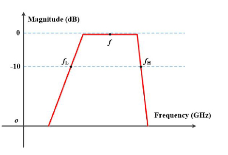
Figure 13: Transmission coefficient of a bandpass filter.
For a bandpass filter, the passband symmetry can be quantified as follows. As shown in Fig. 13, the center frequency of the filter is f, the lower passband edge corresponding to the -10 dB level is fL, and the upper passband edge corresponding to the -10 dB level is fH. For an ideal bandpass filter, the symmetry condition can be expressed as fH-ff-fL, and passband symmetry ratio (r) which can be expressed as r(fH-f)/(f-fL)1. This metric provides a clear and quantitative measure of the passband symmetry.
However, for commonly used bandpass filters, it is challenging to achieve r1. Except, the closer the value of r is to 1, the better the passband symmetry of the filter. Therefore, we define the passband symmetry ratio r as:
Under this definition, the value of r is always greater than 1, which facilitates comparison.
For a more thorough evaluation, comparisons with prior works are presented in Table 1. As seen from Table 1, compared with conventional microstrip tri-band filters, the proposed design demonstrates significantly lower insertion loss while maintaining comparable circuit dimensions. Furthermore, when juxtaposed with tri-band filters based on SIW structures, the filter presented in this work exhibits certain advantages in both insertion loss and circuit size. Moreover, Table 1 also includes tri-band filters based on high-temperature superconducting (HTS) structures [15]–[17]. The aforementioned filters are similarly designed using edge-coupled structures. In terms of insertion loss, the first two passbands of the proposed tri-band filter in this work still exhibit comparable performance with those of HTS-based filters. As shown in Table 1, for the three bandpass filters designed in this paper, the passband symmetry ratio for each passband is less than 1.2, indicating that the design exhibits good passband symmetry.
In summary, the developed filter offers several advantages. Firstly, it employs a /4 TSSIR resonator, which significantly reduces the overall dimensions of the filter compared to existing ones. Secondly, the adoption of a non-edge-coupled structure effectively avoids radiation losses caused by coupling slots, resulting in a low insertion loss, a crucial characteristic for microwave passive devices. Lastly, due to the inherent characteristics of the structure, the single passband of the filter exhibits good symmetry, which is closer to that of an ideal bandpass filter.
V. CONCLUSION
This paper introduces a microstrip line-based tri-band bandpass filter employing quarter-wavelength tri-section stepped impedance resonators (TSSIR). The design process of the proposed filter is characterized by its simplicity and effectiveness. By judiciously adjusting the impedance values of the TSSIR, three distinct passbands can be readily achieved, thus catering to the requirements of multi-band applications. The inherent generation of transmission zeros within the entire operating bandwidth significantly enhances the selectivity, passband symmetry, and band-to-band isolation of the proposed tri-band filter. The consistency between the simulated and measured results further validates the feasibility of the design. These attributes collectively render the filter highly suitable for modern compact tri-band communication systems.
ACKNOWLEDGMENT
The work was supported by Nantong Key Laboratory of Artificial Intelligence New Quality Technology, Jiangsu College of Engineering and Technology and Natural Science and Technology Project of Jiangsu College of Engineering and Technology (GrantJSGYZRJJZD-03).
REFERENCES
[1] D. L. Jin, T. T. Bu, J. S. Hong, J. F. Wang, and H. Xiong, “A tri-band antenna for wireless applications using slot-type SRR,” Applied Computational Electromagnetics Society (ACES) Journal, vol. 29, no. 1, pp. 47-53, Sep. 2021.
[2] M. A. Rahman, S. S. Al-Bawri, S. S. Alharbi, W. M. Abdulkawi, N. M. Jizat, M. T. Islam, and A. A. Sheta, “3D highly isolated 6-port tri-band MIMO antenna system with 360∘ coverage for 5G IoT applications-based machine learning verification,” Scientific Reports, vol. 15, no. 204, pp. 1-23,2025.
[3] K. Yu, Y. Li, and W. Yu, “A compact triple band antenna for Bluetooth, WLAN and WIMAX applications,” Applied Computational Electromagnetics Society (ACES) Journal, vol. 32, no. 5, pp. 424-429, July 2021.
[4] M.-H. Weng and H.-W. Wu, “A novel triple-band bandpass filter using multilayer-based substrates for WiMAX,” Proc. Eur. Microw. Conf., pp. 325-328, Oct. 2007.
[5] X.-Y. Zhang, Q. Xue, and B.-J. Hu, “Planar tri-band bandpass filter with compact size,” IEEE Microw. Wirel. Compon. Lett., vol. 20, no. 5, pp. 262-264, May 2010.
[6] S.-B. Zhang and L. Zhu, “Compact tri-band bandpass filter based on resonators with U-folded coupled-line,” IEEE Microw. Wirel. Compon. Lett., vol. 23, no. 5, pp. 258-260, May 2013.
[7] C.-I.-G. Hsu, C.-H. Lee, and, Y.-H. Hsieh, “Tri-band bandpass filter with sharp passband skirts designed using tri-section SIRs,” IEEE Microw. Wirel. Compon. Lett., vol. 18, no. 1, pp. 19-21, Jan. 2008.
[8] Q.-X. Chu and X.-M. Lin, “Advanced triple-band bandpass filter using tri-section SIR,” Electron. Lett., vol. 44, no. 4, pp. 295-296, Feb. 2008.
[9] A. George, P. Abdulla, and A. Iqubal, “Design and optimization of cost-effective, simple, and miniature tri-band bandpass filter for GSM, WLAN, and WIFI applications,” in 2024 1st International Conference on Trends in Engineering Systems and Technologies (ICTEST), pp. 1-4, 2024.
[10] R. Wu, J. He, X. Tang, Z. Cai, L. Xiao, and F. Xiao, “Tri-band bandpass filter designed by a fast hybrid approach,” Microwave and Optical Technology Letters, vol. 65, no. 7, pp. 1898-1903, July 2023.
[11] X. Wan, Z. Jin, Y. Wang, G. Xu, L. Zhang, Y. Xiong, and L. Wang, “Tri-/quad-/quint-band bandpass filters based on transversal embedded asymmetrical square-ring resonator,” IEEE Access, vol. 12, pp. 92241-92252, 2024.
[12] D. Li, X. Chen, W. Luo, Z. Zheng, and Q. Chen, “Compact tri-band SIW bandpass filters with high selectivity and controllable center frequencies using perturbation structure,” IEEE Transactions on Circuits and Systems II: Express Briefs, vol. 70, no. 11, pp. 4043-4048, Nov. 2023.
[13] L.-Y. Weng and W.-H. Tu, “Three-fourths-mode substrate-integrated waveguide for tri-band bandpass filter,” Microwave and Optical Technology Letters, vol. 66, p. e34032, 2024.
[14] Y. Zhan, Y. Wu, E. Fourn, P. Besnier, and K. Ma, “Synthesis and implementation of multiband SIW bandpass filters based on in-line topology,” IEEE Transactions on Microwave Theory and Techniques, vol. 72, no. 11, pp. 6623-6636, Nov. 2024.
[15] J. Zhang, D. Zhou, D. Zhang, and Q. Liu, “Compact triple-band HTS filter with high selectivity using self-coupled stepped impedance resonator,” Electronics Letters, vol. 56, no. 20, pp. 1067-1069, Sep. 2020.
[16] B. Ren, X. Liu, X. Guan, and Z. Ma, “High-selectivity high-temperature superconducting triband balanced bandpass filter using symmetric stub-loaded resonator,” IEEE Transactions on Applied Superconductivity, vol. 33, no. 8, Nov. 2023.
[17] J. Zhang, Q. Liu, D. Zhang, D. Zhou, and X. Wang, “Tri-band superconducting filter based on crossed resonators with controllable coupling and feeding structures,” International Journal of RF and Microwave Computer-Aided Engineering, vol. 31, p. e22516, 2021.
[18] Ansys HFSS, “R2, Help System, User’s Guide,” ANSYS, 2021.
BIOGRAPHIES

Chuan Shao was born in Shandong Province, China in 1988. He obtained his Ph.D. from Nanjing University of Science and Technology in 2024. His research interests include microwave passive components. Shao is a reviewer for several international journals.
ACES JOURNAL, Vol. 40, No. 7, 609–616
doi: 10.13052/2024.ACES.J.400705
© 2025 River Publishers