A Miniaturized Wide-stopband Wide-passband Cavity Filter with Two Asymmetric Stepped Probes
Panfeng Bao, Yulun Wu, Yufeng Shen, Jinrong Liu, and Yaqi Li
1Changsha Aeronautical Vocational and Technical College
Changsha 410000, China
223121110079@njust.edu.cn, 15116220284@163.com, longyong2025@163.com
2Nanjing University of Science and Technology
Nanjing 210000, China
3Northeastern University at Qinhuangdao
Qinhuangdao 066004, China
202112694@stu.neu.edu.cn, 202112708@stu.neu.edu.cn
Submitted On: March 13, 2025; Accepted On: May 16, 2025
ABSTRACT
In this paper, a miniaturized cavity filter with wide-stopband and wide-passband is proposed. Because of the bended stub-loaded resonator (BSLR), the proposed cavity filter successfully excites three TEM modes, namely TEM-I, TEM-II and TEM-III. The low-frequency transmission zero (LFTZ) is generated by the lateral probe, and the high-frequency transmission zero (HFTZ) is generated by the lateral stub. The lateral metal cylinder can concentrate the electric field of the stray mode, leading to a high suppression level. The asymmetric vertical arrangement of the probes can suppress the fundamental TE mode and several high-order modes. Therefore, a stopband with a bandwidth of 2.02 times the center frequency is formed. The proposed cavity filter has a bandwidth of 42% and an electrical size of 0.260.250.22. It has several advantages applied to the 5G communication system.
Index Terms: Cavity filter, miniaturization, wide-band, wide-stopband.
I. INTRODUCTION
With the development of modern communication technology, cavity filters have become an indispensable part of microwave systems. Cavity filters are gradually moving towards wide-stopband, high-power capacity and low insertion loss.
Nowadays, researchers and engineers are exploring ways to design multi-mode cavity filters. The first way is to cascade several single cavities whose resonant modes are generally TE or TM modes [1–3]. In [4], a rectangular cavity filter is proposed. This cavity filter uses two pairs of degenerate modes to excite a quadruple-mode passband response. The proposed cavity has a relative bandwidth of 1.35% and a high-quality factor of 14500. In [5], a cross-coupled cavity filter is proposed. A thin cavity is used to introduce a cross coupling between two main resonant cavities, the TE mode of this thin cavity has been set away from the center frequency. The proposed cavity filter realizes a bandwidth of 1.84% and a stopband with a bandwidth of 1.68 times the center frequency. It is worth noting that the first way can also be used to design the filtering antennas. In [6], several cavities with TE modes are cascaded as the horn of the proposed filtering antenna. The proposed filtering antenna has a bandwidth of 4% and a directional realized gain of 13.5 dBi.
The second way of designing cavity filters is to load multi-mode resonators into the resonant cavity [7–10]. In [11], several short-circuited metal cylinders are loaded inside the cavity to realize a triple-TEM-mode response. Although the performance of the cavity filter proposed in [11] is mediocre, it fully proves the feasibility of the second way. In [12] and [13], the method of cascading several resonators has been used to achieve multiple resonances. They all achieve high-selectivity and a high stopband suppression level. In [14], the ring-shaped microstrip lines are used to couple several coaxial resonators. The proposed cavity filter has 2% bandwidth and extremely low return loss. The dielectric coaxial resonators can also be used in cavity filters. In [15], a pair of dielectric coaxial resonators are used to make a wide-stopband and a high suppression level. The proposed cavity filter realizes a bandwidth of 9.6% and a stopband with a bandwidth of 4.5 times the center frequency. Like the first way, the second way can also be used to design filtering antennas. In [16], a coaxial filtering antenna is proposed with extreme high-selectivity of 2300 dB/GHz. The proposed filtering antenna uses dual-post coaxial resonators to transversely cascade. In [17], a filtering antenna is successfully designed by combining the first way and the second way. The proposed filtering antenna uses a main resonant cavity with a TE mode, a TE mode and a TEM mode.
For the cavity filters, the above works can hardly realize wide-passband and wide-stopband simultaneously. In this paper, a compact cavity filter with wide-passband and wide-stopband is proposed. The proposed filter uses three TEM modes to form a 42% passband. A special lateral metal cylinder and the asymmetric vertical arrangement of two probes are used to generate a stopband with a bandwidth of 2.02 times the center frequency. Due to the resonant frequencies of the TEM modes being lower than the resonant frequency of the fundamental TE mode, the proposed cavity filter can also achieve miniaturization. Moreover, the equivalent circuit is also proposed [18] for engineering applications.
II. DESIGN AND ANALYSIS
A. Physical structure of the proposed cavity filter
The structure of the proposed cavity filter is shown in Fig. 1. The proposed cavity filter is composed of a rectangular cavity, a bended stub-loaded resonator (BSLR), a perturbed metal cylinder and two stepped probes. The BSLR consists of a lateral stub and a longitudinal stub. Two mutually perpendicular probes are loaded inside the cavity to couple with the BSLR. The stepped metal cylinders are loaded onto the terminals of the probes. A lateral perturbed metal cylinder is loaded onto the sidewall of the cavity.
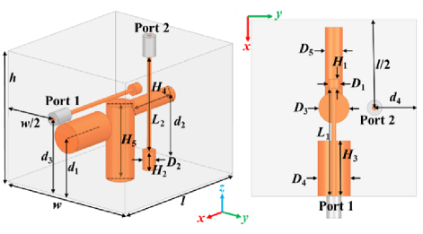
Figure 1: Physical structure of the proposed cavity bandpass filter: (a) Three-dimensional view and (b) xoy plane (unit: mm): , , , , , , , , , , , , , , , , , .
B. Evolution steps of the proposed cavity filter
In order to describe more clearly the design process of the proposed cavity filter, the evolution steps of the proposed cavity filter are displayed in Fig. 2. The reflection coefficients and the insertion losses are displayed in Figs. 3 (a) and (b), respectively.
The interior of the BPF.I is loaded with a longitudinal SLR and two mutually perpendicular probes. The BPF.I has two TEM modes and a low-frequency transmission zero (LFTZ) The stopband is narrow and the high-frequency selectivity is poor. Moreover, the impedance matching greatly needs to be improved. Figure 6 (c) shows the electric-field distribution of the LFTZ. At the LFTZ, the electric-field energy concentrates on the lateral probe, so the transmission is almost zero.
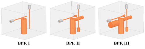
Figure 2: Evolution steps of the proposed cavity filter.
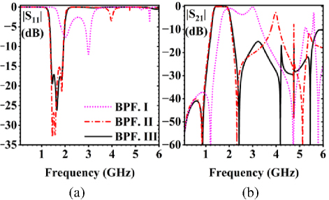
Figure 3: S-parameters of the cavity filter mentioned in the evolution steps: (a) Reflection coefficients and (b) insertion losses.
After connecting a lateral stub to the longitudinal stub to form the BSLR, and loading stepped metal cylinders onto the terminals of two probes, the BPF.II is formed. Since the equivalent electrical length of the BSLR is smaller than the equivalent electrical length of the SLR in BPF.I, the center frequency of the passband moves towards low-frequency. The impedance matching has improved significantly because of the stepped impedance characteristics. Three TEM modes, namely TEM-I, TEM-II and TEM-III, are successfully generated at 1.46 GHz, 1.58 GHz and 1.87 GHz, respectively. Figure 4 shows the electric-field distribution of TEM-I, TEM-II and TEM-III in the xoz and yoz planes. Selectivity is improved significantly by introducing a new high-frequency transmission zero (HFTZ) at 2.38 GHz. However, the stopband of BPF.II is still narrow because a stray mode, namely TEM-IV, is generated at 3.98 GHz. Figure 6 (d) shows the electric-field distribution of the HFTZ. At the HFTZ, the electric-field energy concentrates on the lateral metal cylinder, so the transmission is almost zero.
After loading a lateral perturbed metal cylinder onto the side wall of the cavity, the proposed cavity filter named BPF.III is formed. The TEM-IV is suppressed greatly by the perturbed metal cylinder. The origin and the suppressed TEM-IV are displayed in Figs. 6 (a) and (b), respectively. It can be seen that the perturbed metal cylinder can pull and focus most electric-field energy, so the electric-field energy cannot be coupled well from the lateral probe to the longitudinal probe. The stopband range increases to 3.4 GHz (2.2-5.6 GHz). The maximum return loss is lower than -18 dB. It is obvious that the proposed cavity filter has good impedance matching and wide-stopband.
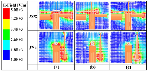
Figure 4: Electric-field distributions of the proposed cavity filter: (a) TEM-I, (b) TEM-II, and (c) TEM-III.
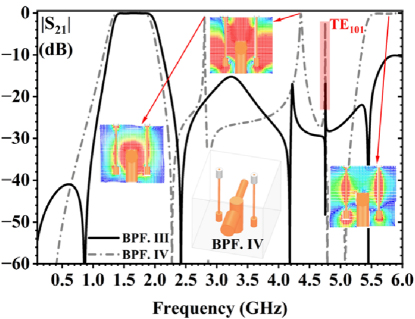
Figure 5: Insertion losses, physical structure and electric-field distributions of the BPF.III and BPF.IV.
C. Illustration of the arrangement of the probes
In order to explain the reason for the arrangement of the mutually vertical probes in the proposed cavity filter, a comparison of the insertion loss of the proposed filter and BPF.IV are displayed in Fig. 5. It can be seen that several transmission modes with symmetric electric field are successfully excited due to the parallel stepped probes of BPF.IV. Intuitively, these transmission modes are destroyed by mutually perpendicular probes. In order to quantitatively explain why these transmission modes collapse in the proposed cavity filter, the coupling intensity K is introduced, as shown in (1). E represents the electrical field distribution introduced by the probes. E represents the electrical field distribution of a certain order mode in the cavity filter. V represents the volume of the metal cavity. Clearly, the K of the proposed cavity filter is significantly less than the K of BPF.IV.
| (1) |
To further prove the accuracy of the above principle, Figs. 6 (e) and (f) show the electric-field distribution of the TE mode in the proposed cavity filter and BPF.IV. In the proposed cavity filter, the direction of the electric field of the probe is perpendicular to the spatial distribution of the electric field of the TE mode, resulting in zero overlap integration of the two field distributions. This phenomenon leads to discontinuities in the TE mode, making it not well excited.
D. Parameters analysis of the proposed cavity filter
The S-parameters of the proposed cavity filter with different D, d and H are shown in Fig. 7. When the diameter of the lateral cylinder of BSLR D increases from 3.8 mm to 5.8 mm, the center frequency of the passband moves to high-frequency. When the length of the lateral probe increases from 25 mm to 26 mm, the LFTZ moves to low-frequency. When the length of the lateral cylinder of BSLR H increases, the HFTZ moves to high-frequency. The quality factor Q of TEM-I increases, the Q of TEM-II remains unchanged and the Q of TEM-III decreases. The Q of TEM-II remains stable due to the weak electric field around its lateral stub, where length variations minimally affect the characteristics ofTEM-II.
E. Equivalent circuit of the proposed cavity filter
The equivalent circuit of the proposed cavity filter is also analyzed. The electrical impedance Z of a cylinder can be calculated by (2). The capacitor C can be calculated by (3). Parameter a denotes the axial length of the cylindrical cavity. Parameter r denotes the radius of the cylinder. The resonant frequency can be calculated by (4). The parameter p denotes the order of the proposed cavity filter. Parameters and denote the i-th inductor and j-th capacitor, while m and n represent the total number of inductors and capacitors, respectively.
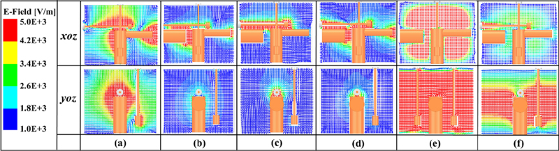
Figure 6: Electric-field distributions of BPF.II, the proposed cavity filter and BPF.IV: (a) Electric field distribution of TEM-IV of BPF.II, (b) electric-field distribution of TEM-IV of the proposed cavity filter, (c) electric-field distribution at LFTZ, (d) electric-field distribution at HFTZ, (e) electric-field distribution of TE mode of BPF.IV, and (f) electric-field distribution of TE mode of the proposed cavity filter.
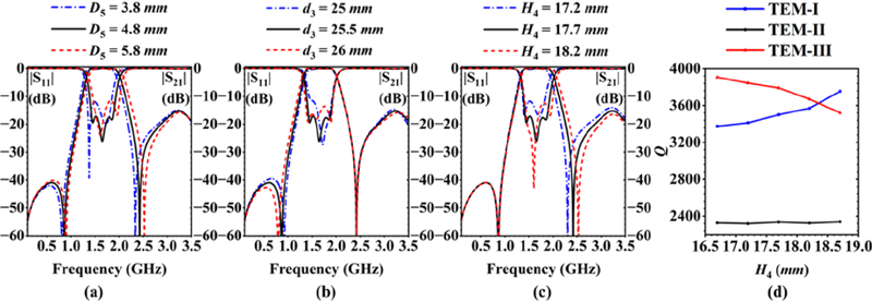
Figure 7: Relative parameters of the proposed cavity filter: (a) S-parameters with different D, (b) S-parameters with different d, (c) S-parameters with different H, and (d) quality factor Q with different H.
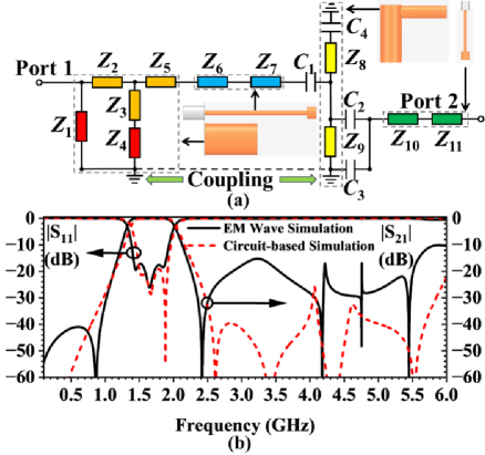
Figure 8: Relative information about the equivalent circuit of the proposed cavity filter: (a) Equivalent circuit of the proposed cavity filter and (b) S-parameters of the EM wave simulation and circuit-based simulation.
Insertion loss and impedance matching of the proposed cavity filter were simulated using the Advanced Design System software based on the equivalent circuit, and the results are compared with those from electromagnetic (EM) wave simulation, as depicted in Fig. 8 (b). The center frequencies, the impedance matchings and the insertion losses in the passband of the two simulation methods are basically the same. Each part of the proposed cavity filter can be matched to the corresponding impedance value in the equivalent circuit. Therefore, the equivalent circuit has good consistency with the proposed EM model.
| (2) | ||
| (3) | ||
| (4) |
III. RESULTS AND DISCUSSION
To verify the rationality of the design, the proposed cavity filter is fabricated and then tested by the vector network analyzer. Figure 9 shows the simulated and tested results, with a photograph of the fabricated cavity filter. The material of the fabrication is aluminum-plated silver. The proposed cavity filter achieves miniaturization with a compact size of 0.260.250.22. It can be seen that the tested results are roughly consistent with the simulation ones. The measured impedance matching deviates slightly from the simulated results, which can be attributed to inaccuracies in the fabrication process and limitations of the testing equipment. The measured S-parameters show that the proposed cavity filter has three resonant frequencies (1.47 GHz, 1.65 GHz and 1.89 GHz). The operating bandwidth is 42% from 1.33 GHz to 2.03 GHz and the insertion loss of the passband is 0.6 dB. All stopband suppression levels are higher than 15 dB. For the fabrication, the bandwidth of the stopband is 3.8 GHz from 2.2 GHz to 6 GHz. Table 1 compares the proposed cavity filter and previous works. It can be seen that the proposed cavity filter has good performance in all aspects. Consequently, the proposed cavity filter achieves miniaturization, demonstrating superior filtering response and wide-stopband characteristics.
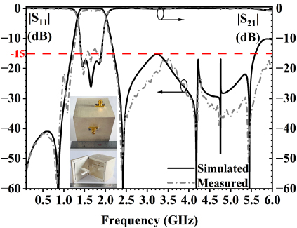
Figure 9: Simulated and measured S-parameters (inset photograph of the fabrication).
Table 1: Comparison with previous works
| Ref. | Electrical Size | BW | SR |
| [4] | 1.11.11.15 | 1.35% | 0.08f |
| [5] | 1.870.340.75 | 1.84% | 1.68f |
| [9] | 0.410.20.41 | 58% | 0.63f |
| [11] | 0.120.120.08 | 4.64% | 0.25f |
| [15] | 0.761.010.08 | 9.6% | 4.5f |
| Pro. | 0.260.250.22 | 42% | 2.02f |
BW: relative bandwidth, SR: stopband range, f: center frequency.
IV. CONCLUSION
A compact wide-passband wide-stopband cavity filter is proposed in this paper. The proposed cavity filter utilizing a BSLR stimulates three TEM modes, with the lateral probe creating LFTZ and the lateral stub generating HFTZ. Stray mode suppression is enhanced through electric-field concentration via lateral metal cylinders, while the asymmetric and vertical probes inhibit both fundamental TE and higher-order modes, forming a stopband with bandwidth of 2.02 times center frequencies. Featuring a wide-bandwidth of 42% and compact electrical dimensions, the design demonstrates engineering reliability through its proposed equivalent circuit. This solution offers significant advantages for 5G systems, including compact size, wide-stopband coverage and broad passband.
ACKNOWLEDGMENT
This research was funded by Hunan Provincial Department of Education Excellent Youth Project (Grant No. 23B1104). APC was funded by Hunan Provincial Department of Education.
REFERENCES
[1] Z.-C. Guo, L. Zhu, and S.-W. Wong, “Synthesis of transversal bandpass filters on stacked rectangular H-plane waveguide cavities,” IEEE Trans. Microwave Theory Tech., vol. 67, no. 9, pp. 3651-3660, Sep. 2019.
[2] S. Bastioli, R. Snyder, C. Tomassoni, and V. de la Rubia, “Direct-coupled TE-TM waveguide cavities,” IEEE Microwave Wireless Tech. Lett., vol. 33, no. 6, pp. 819-822, June 2023.
[3] E. López-Oliver and C. Tomassoni, “3-D-printed dual-mode filter using an ellipsoidal cavity with asymmetric responses,” IEEE Microwave Wireless Compon. Lett., vol. 31, no. 6, pp. 670-673, June 2021.
[4] G. Basavarajappa and R. R. Mansour, “A high-Q quadruple-mode rectangular waveguide resonator,” IEEE Microwave Wireless Compon. Lett., vol. 29, no. 5, pp. 324-326, May 2019.
[5] Z.-C. Guo, L.-Y. Li, A. Wang, X. Wang, and L. Zhu, “Cross-coupled waveguide bandpass filters with inline footprint and extremely flexible transmission zeros,” IEEE Microwave Wireless Tech. Lett., vol. 35, no. 5, pp. 525-528, May 2025.
[6] K. Mohan Patnaik, G. Basavarajappa, and H. Sigmarsson, “An innovative design methodology of a novel multifunctional all-pole filtering horn antenna,” IEEE Microwave Wireless Tech. Lett., vol. 35, no. 1, pp. 35-38, Jan. 2025.
[7] Z.-C. Zhang, X.-Z. Yu, S.-W. Wong, B.-X. Zhao, J.-Y. Lin, X. Zhang, and K.-W. Tam, “Miniaturization of triple-mode wideband bandpass filters,” IEEE Trans. Compon. Packag. Technol., vol. 12, no. 8, pp. 1368-1374, Aug. 2022.
[8] M. Y. Sandhu, S. Afridi, A. Lamecki, R. Gómez-García, and M. Mrozowski, “Miniaturized inline bandpass filters based on triple-mode integrated coaxial-waveguide resonators,” IEEE Access, vol. 11, pp. 81196-81204, 2023.
[9] M. Hameed, G. Xiao, and L. Qiu, “Triple-mode wideband bandpass filter using simple perturbation in metallic-loaded rectangular waveguide cavity,” Electromagnetics, vol. 38, no. 5, pp. 303-316, 2018.
[10] Z.-M. Li, Y.-Q. He, J.-Y. Lin, Z.-C. Zhang, X. Zhang, L. Zhu, and S.-W. Wong, “X-band air-filled coaxial bandpass filter with wideband input-reflectionless performance,” Microwave Opt. Technol. Lett., vol. 67, Jan. 2025.
[11] Y. Wu, L. Jin, and Z. Lu, “A triple-quasi-TEM-resonance dielectric cavity for bandpass filter design,” IEEE Microwave Wireless Compon. Lett., vol. 32, no. 8, pp. 950-952, Aug. 2022.
[12] M. Y. Sandhu, A. Lamecki, R. Gómez-García, and M. Mrozowski, “Compact quasi-elliptic-type inline waveguide bandpass filters with nonlinear frequency-variant couplings,” IEEE Trans. Microwave Theory Tech., vol. 71, no. 11, pp. 4933-4946, Nov. 2023.
[13] M. R. Salehi, B. Ghalamkari, and A. K. Nia, “Design and fabrication of a five-order narrow-band coaxial filter based on cross coupling and non-cross-coupling methods,” IETE Journal of Research, vol. 70, no. 11, pp. 8110-8117,2024.
[14] M. Salek, Y. J. Wang, and M. Lancaster, “Two-GHz hybrid coaxial bandpass filter fabricated by stereolithography 3-D printing,” Int. J. RF Microw. Comput. Aided Eng., vol. 31, 2021.
[15] K. Zhao and D. Psychogiou, “Spurious suppression techniques for 3-D printed coaxial resonator bandpass filters,” IEEE Microwave Wireless Compon. Lett., vol. 32, no. 1, pp. 33-36, Jan. 2022.
[16] J. Ma, K.-R. Xiang, and F.-C. Chen, “A high-selectivity filtering antenna based on dual-post coaxial resonators,” IEEE Trans. Antennas Propag., vol. 72, no. 2, pp. 1899-1904, Feb.2024.
[17] K.-R. Xiang, F.-C. Chen, Q.-X. Chu, and Q. Xue, “High selectivity waveguide filtering antennas using mixed-mode cavity resonator,” IEEE Trans. Microwave Theory Tech., vol. 70, no. 9, pp. 4297-4307, Sep. 2022.
[18] B. Dwivedy and S. K. Behera, “Modelling, analysis and testing of an active element based wide-band frequency tunable compact rat-race hybrid,” AEU-Int. J. Electron. C., vol. 103, pp. 24-31, May2019.
BIOGRAPHIES
Panfeng Bao is currently pursuing the Ph.D. degree in Armament Science and Technology at the State Key Laboratory of Transient Physics, Nanjing University of Science and Technology, Nanjing, China. Since 2017, he has been with Changsha Aeronautical Vocational and Technical College, Changsha, China, where he is currently a lecturer with the School of Aeronautical Mechanical Manufacturing. His research interests focus on dynamic response analysis of weapon systems, mechanical fault diagnosis under extreme conditions, RF device design and RF communication in weapon systems.

Yulun Wu is currently pursuing the B.E. degree in Northeastern University at Qinhuangdao, Qinhuangdao, China. Since 2022, he has been working on RF devices and has published in several conferences and journals. His current interests include terahertz communication and microwave devices and systems.

Yufeng Shen is an Associate Professor at Changsha Aeronautical Vocational and Technical College, Changsha, China. His main research focus is aircraft digital manufacturing technology.
Jinrong Liu is an Experimental Engineer at Changsha Aeronautical Vocational and Technical College, Changsha, China. He is a recipient of the Hunan Province May 1st Labor Medal and National Technical Expert, with main research focus on mechatronics technology.

Yaqi Li is currently pursuing the B.E. degree at Northeastern University in Qinhuangdao, Qinhuangdao, China. Since 2022, she has conducted in-depth research on the design and application of microwave passive integrated devices such as coaxial cavity filters and power dividers.
ACES JOURNAL, Vol. 40, No. 5, 451–456
doi: 10.13052/2025.ACES.J.400509
© 2025 River Publishers