A Broadband Metasurface for Effective Control of Transmission Phase by Applied Voltage
Zhen Wang1, Ajay K. Poddar2, Ulrich L. Rohde2, and Mei Song Tong1
1Department of Electronic Science and Technology, Tongji University Shanghai 201804, China
2210232@tongji.edu.cn; mstong@tongji.edu.cn
2Synergy Microwave Corporation, 201 McLean Boulevard, Paterson, NJ 07504, USA
akpoddar@ieee.org; u.l.rohde@ieee.org
Submitted On: March 18, 2025 Accepted On: September 23, 2025
Abstract
This paper presents a reconfigurable transmissive metasurface operating at GHz. The metasurface consists of a four-layer stacked structure of circular radiating patches, with varactor diodes integrated into the patches to achieve continuous transmission phase control. The structure exhibits a transmission loss of less than dB and a relative bandwidth of approximately . By tuning the capacitance of the varactor diodes, the transmission phase can be precisely and continuously adjusted. Compared to switch-diode-based metasurfaces, this approach offers a simpler design and enables dynamic continuous phase modulation. Both simulation and measurement results, including the relationship between transmission magnitude and phase shift versus bias voltage, show strong agreement. The metasurface demonstrates excellent bandwidth characteristics. This work provides a valuable strategy for designing dynamically tunable broadband metasurfaces and holds significant potential for applications in high-gain phased array antennas and efficient beamforming systems.
Keywords: Active metasurface, transmission phase, varactor tuning..
1 INTRODUCTION
Metamaterials are novel synthetic materials engineered to achieve specific properties not normally found in nature [1]. However, large volume and inflexibility of normal metamaterials make them impractical in many applications. Based on the generalized Snell’s law, metasurface, a kind of metamaterial with a planar structure, was proposed [2]. Since then, the study of phase gradient metasurfaces (PGMS) has attracted the interest of many researchers. PGMS is capable of providing predefined in-plane wave vectors to manipulate the directions of the refracting/reflecting waves [3]. The wave beam can be controlled by introducing sudden phase changes at different positions on the plane and making its distribution meet certain rules.
In [4], a multilayer square-ring metallic structure was employed to design a phase metasurface, where transmission phase variation was achieved by adjusting the perimeter of the square rings. In addition, the design procedure of some metasurfaces is to change the size of unit cell firstly, then combine them properly to achieve electromagnetic wave control [5, 6, 7, 8, 9, 10].
Another way to adjust the phase of the unit is to rotate the metasurface unit. A new type of metasurface design is used to generate vortex beams [11], the proposed metasurface units are rotated at different angles and then distributed regularly. In [12], a transmission–reflection-integrated metasurface is proposed, which enables full-space amplitude and phase control of circularly polarized (CP) waves. By rotating the receiving and transmitting patches of each meta-atom around their respective feed points, the transmission and reflection phases can be independently tailored. Also, a similar principle is used to adjust the phase of the unit in [13, 14, 15, 16].
The above two methods to change the phase of the unit are realized by changing the shape of the unit structure under the passive condition. Changing the shape of the unit structure compromises the dynamic control of the phase. In order to dynamically control the transmission phase, a multilayer metasurface unit is proposed, and the PIN diodes are attached to each unit [17]. However, since the PIN diode only has two states, on and off, it is complicated for this kind of metasurface to realize continuous controlling of phase. Another type of active metasurface for vortex beam generation is designed in [18]. The method is to divide the entire metasurface into several regions and then control capacitance in different regions. But this active metasurface only allows full phase adjustment within the limited bandwidth. Reference [19] presents a metasurface capable of both transmission and reflection functionalities, where the switching between transmission and reflection modes is achieved using only a single PIN diode. However, the phase control of the unit cells in this design relies solely on geometric dimension variations, making dynamic phase tuning unattainable. Moreover, the integration of varactor diodes into metasurfaces enables dynamic phase tuning. In [20], a varactor-based metasurface was developed to achieve continuous phase modulation. Under different bias voltages, the unit cell demonstrated a transmission phase shift of and a reflection phase shift of . However, the design exhibited an insertion loss of approximately dB. In [21], a novel metasurface incorporating varactor diodes was proposed, capable of simultaneously controlling both amplitude and phase, and achieving phase tuning. Nevertheless, the operational bandwidth was relatively narrow, limited to only .
In this paper, an active metasurface which can dynamically adjust the transmission phase over a broad bandwidth is proposed and its prototype has been simulated in [22]. Each unit of the metasurface consists of a circular patch and two strip patches, with two varactor diodes placed in the gap between the two types of patches. By changing the capacitance of the varactor diodes, the transmission phase can be changed efficiently. The two ends of the varactor diode are fed by the strip patch and the circular patch respectively to avoid the influence of the re-designed feed structure on the metasurface performance. The simulation and measurement results show that the metasurface can reach a bandwidth of and a tunability of transmission phase over with a transmission magnitude more than .
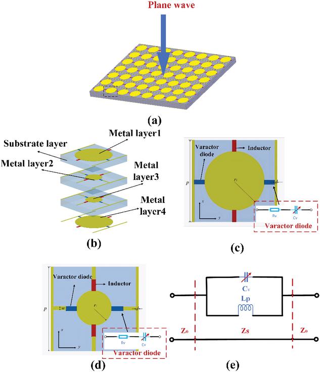
Figure 1 Structure of the proposed metasurface. (a) Schematic diagram of the overall metasurface structure. (b) Cross-section view. (c) Circular patch layer structure with radius . (d) Circular patch layer structure with radius . (e) Single-layer radiating patch resonant circuit model structure.
2 TUNABLE METASURFACE DESIGN AND ANALYSIS
2.1 Metasurface unit cell design
The perspective structure of the proposed active transmissive metasurface is shown in Fig. 1 (a). Its metasurface structure can produce different electromagnetic responses with continuously adjustable phases to incident waves. Figure 1 (b) presents the geometrical model of the unit cell of the active metasurface. The structure primarily consists of three dielectric substrate layers and four metallic patch layers. The substrates are square-shaped and made of Rogers AD260A material, with a thickness of 1.4 mm, a relative permittivity of 2.65, and a loss tangent of . The first and fourth metallic layers employ circular patches with a radius of , while the second and third metallic layers use circular patches with a radius of . The significant difference in patch radii between the two groups results in distinct frequency responses. For a circular patch with radius , the approximate value of the resonant frequency is given by the following equation [23]
| (1) |
where is the resonant frequency of the metasurface unit, is the speed of light, is the radius of the circular patch, and is the effective dielectric constant.
Two varactor diodes are placed symmetrically on both sides of the circular patch. Each diode has one terminal connected to the circular patch and the other terminal connected to a bias line etched on the bottom layer of the substrate. The equivalent resonant circuit of a single layer is illustrated in Fig. 1 (e). The incident electromagnetic wave can be modeled as a parallel resonant circuit comprising an inductance and a capacitance [24]. where, represents the equivalent capacitance between the metallic bias line and the circular patch, while corresponds to the equivalent inductance of the metallic patch. Consequently, the circular patch no longer behaves as a pure resonant cavity but forms an -tunable resonator, with its resonant frequency determined by
| (2) | |
| (3) |
where denotes the capacitance between the metallic patches, and represents the variable capacitance of the varactor diode. The values of and are determined by the geometry of the patches and the corresponding current paths. Therefore, its equivalent resonant structure is not only determined by the geometric dimensions, but also affected by the variable capacitance . The configurations of the two types of circular patches are shown in Figs. 1 (b) and (c). The components marked in blue represent varactor diodes, specifically the MAVR-000120-14110, with a capacitance range of pF, which ensures adequate tunability to meet the capacitance requirements of the metasurface. The components marked in red are inductors with an inductance value of nH, used to isolate AC signals. The geometric parameters are defined as follows: mm, mm, mm, mm. The unit cell is simulated using the finite element method (FEM), with periodic boundary conditions applied to all four sidewalls. The simulated transmission characteristics of a single-layer metallic patch on a single dielectric substrate are presented in Figs. 2 and 3. The simulation results show that when the patch area of the unit cell is larger, the transmission magnitude is easier to be stabilized in a certain range. When the patch area of the unit cell is smaller, the adjustment range of transmission phase can be larger. At the same time, it is found that for a transmission metasurface, it is difficult to achieve a phase adjustment of by using the structure of single patch and substrate, but such a phase adjustment can be easily achieved by simply adding a phase offset in a multi-layer structure.
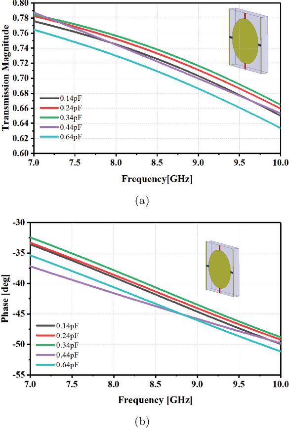
Figure 2 Simulation of transmission characteristics for a single-layer circular radiating patch with a radius of . (a) Transmission magnitude. (b) Transmission phase.
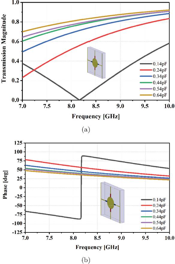
Figure 3 Simulation of transmission characteristics for a single-layer circular radiating patch with a radius of . (a) Transmission magnitude. (b) Transmission phase.
2.2 Transmission phase principle analysis
As shown in Fig. 1 (e), the impedance of the parallel resonant circuit of a single-layer metal patch is , which is put into the transmission model, and the electromagnetic transmission matrix [24] can be expressed as
| (4) | ||
where is the wave impedance in free space. The transmission coefficient of a single-layer metal patch can be expressed as
| (5) |
According to the above analysis, the transmission amplitude and phase of the artificial electromagnetic structure are related to the equivalent electrical parameters. By changing the electromagnetic structure to affect the corresponding electrical parameters, the amplitude and phase of the incident electromagnetic wave can be controlled. The overall matrix transmission parameters can be described as [25].
| (6) | ||
where , , , and represent the first matrix, second matrix, third matrix, and overall cascaded matrix, respectively, and . When the characteristics of the selected substrate remain constant, the main factors affecting the transmission characteristics are the matrices of the two conductive layers, so equation (6) can be simply written as
| (7) |
As the number of layers increases, the transmission phase can be equivalent to the phase superposition of each conductive layer unit. Therefore, using multilayer conductive patches can enhance the transmission phase of the metasurface unit.
2.3 Metasurface design
As shown in Fig. 1 (a), the overall structure of the proposed metasurface consists of unit cells. The dimension of the whole structure is 100.0 mm 90.0 mm. Since each unit cell of the metasurface has no need to be fed independently, experimental measurements are facilitated. In order to avoid the tedious design of additional feeding structure, the strip patch of every unit cell can directly function as the feeding structure to feed one end of the varactor diode [26] while the circular patch can be used to feed the other end of the varactor diode. Also, the inductors are added for blocking alternating current to reduce the influence of the feeding structure on the performance of the metasurface [27]. When the direct current (DC) power supply is used to feed the metasurface, the positive pole of the power supply is connected with the circular patch while the negative pole is connected with the strip patch. The width of all the bias lines is mm.
Figure 4 Simulated results of the proposed transmission metasurface consisting of the unit cell with different capacitance values. (a) Transmission phase. (b) Transmission magnitude.
3 SIMULATION AND MEASUREMENT RESULTS
In order to ensure that the transmission metasurface can achieve a phase shift of , the varactor diode values in the range of pF are determined. From the simulation results as shown in Fig. 4, the phase and magnitude of the transmission metasurface at different capacitance values can be intuitively obtained respectively. The simulation results show that within the range of GHz from GHz to GHz, the transmission phase can be adjusted by adjusting the capacitance value of the varactor diode. Meanwhile, the transmission magnitude can be stabilized above , indicating the transmission loss remains within 2 dB across the operating frequency band. This means that the transmission phase can be continuously and dynamically adjusted by at each frequency point in the frequency band, while the transmission amplitude is also well controlled. It is noted that, due to the resonance in the metasurface with the capacitance of pF, the transmission magnitude is decreased significantly near GHz, resulting in the maximum bandwidth limitation of the proposed metasurface.
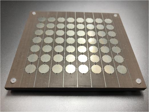
Figure 5 Photograph of the fabricated metasurface sample.
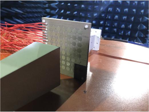
Figure 6 Measurement setup.
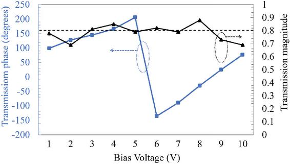
Figure 7 Measurement results of transmission phase and transmission magnitude at different bias voltages at GHz.
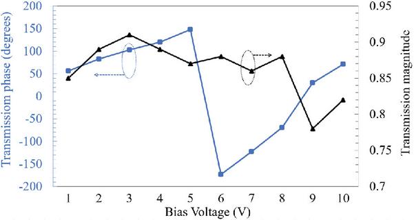
Figure 8 Measurement results of transmission phase and transmission magnitude at different bias voltages at GHz.
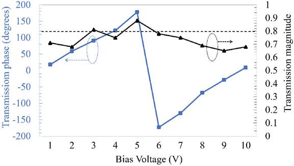
Figure 9 Measurement results of transmission phase and transmission magnitude at different bias voltages at GHz.
An metasurface as shown in Fig. 5 was fabricated by using a printed circuit board to verify the performance of the metasurface proposed in this paper. The metasurface was measured in a microwave anechoic chamber as shown in Fig. 6, and the different layers of the metasurface are fixed with plastic screws. The wires connect the metasurface and the DC power supply ZF-303D to feed the two ends of the varactor diode. A PNA network analyzer of KEYSIGHT N5227A and two horn antennas were selected to measure the fabricated metasurface. The end face dimensions of the two horn antennas ( GHz) are mm 42.0 mm, which is smaller than that of the metasurface. To accurately characterize the transmission amplitude and phase response of the metasurface under various bias conditions, a near-field measurement setup was employed, with a fixed test distance of mm between the horn antennas and the metasurface.
The transmission magnitude and phase of the metasurface controlled by different uniform bias voltages at GHz, GHz and GHz are shown in Figs. 7–9, respectively. By adjusting the voltage at both ends of varactor diode from V to V, the fabricated metasurface realizes full phase adjustment of transmission phase. However, at GHz and GHz, the transmission amplitude is measured below at some bias voltages. One reason for the differences between the measurement results and the simulation results is that the size of the varactor diode is very small and there is a size error in production, that is, the length and width of all varactors are not exactly the same. Another reason is the limited measurement conditions. In addition, the phase shows a good linearity with the biased voltage.
Table 1 Comparison between proposed design and others
| Source | Transmission | Tunability | Bandwidth |
| Phase | |||
| [18] | 360° | Yes | |
| [20] | 245° | Yes | |
| [21] | 360° | Yes | |
| [28] | 2bit | Yes | |
| [29] | 360° | Yes | |
| This Work | 360° | Yes |
For a comparison, Table 1 lists the transmission phase tunability, and relative bandwidth of other designs and this work. It should be noted that the operating bandwidth is determined on the basis that transmission phase control can be achieved at all frequencies and the transmission amplitude is above . Reference [18] uses a single-layer dielectric substrate design. While it uses a varactor diode to achieve phase tuning, its operating bandwidth is only . Compared with [20, 21], and [29], all of which use a three-layer dielectric substrate and add a varactor diode, this design has a wider operating bandwidth while achieving a dynamic phase tuning of . Reference [28] uses a double-layer substrate design, but it only achieves a 2-bit tuning phase. This shows that this design is superior to other designs in terms of relative bandwidth and, more importantly, the transmission phase can be dynamically and continuously controlled.
4 CONCLUSION
A broadband transmission metasurface with a dynamic phase adjustment is proposed. Through the analysis of the equivalent circuit of the transmission model, a new optimization method to stabilize the transmission amplitude of the metasurface is adopted. Simulation results show that the proposed transmission metasurface can achieve an adjustment of for the transmission phase in the working frequency band of about GHz, while maintaining the transmission magnitude above . In order to verify the performance of the proposed metasurface, a sample including unit cells is fabricated, and the measurement results are consistent with the simulation results. This work will benefit significantly the development of wave manipulation technology used for beamforming in high-gain phased antennas.
REFERENCES
[1] C. L. Holloway, E. F. Kuester, J. A. Gordon, J. O’Hara, J. Booth, and D. R. Smith, “An overview of the theory and applications of metasurfaces: The two-dimensional equivalents of metamaterials,” IEEE Antennas Propag. Mag., vol. 54, no. 2, pp. 10–35, Apr. 2012.
[2] N. Yu, P. Genevet, M. A. Kats, F. Aieta, J.-P. Tetienne, F. Capasso, and Z. Gaburro, “Light propagation with phase discontinuities: Generalized laws of reflection and refraction,” Science, vol. 334, no. 6054, pp. 333–337, Oct. 2011.
[3] H. Li, G. Wang, H. Xu, T. Cai, and J. Liang, “X-band phase-gradient metasurface for high-gain lens antenna application,” IEEE Trans. Antennas Propag., vol. 63, no. 11, pp. 5144–5149, Nov. 2015.
[4] H. Hao, S. Zheng, Y. Tang, and X. Ran, “Broadband transmissive amplitude-and-phase metasurface for vortex beam generation and hologram,” Phys. Lett. A, vol. 434, p. 128036, 2022.
[5] Y. Lv, X. Ding, B. Wang, and D. E. Anagnostou, “Scanning range expansion of planar phased arrays using metasurfaces,” IEEE Trans. Antennas Propag., vol. 68, no. 3, pp. 1402–1410, Mar. 2020.
[6] H. Ali, M. U. Afzal, K. P. Esselle, and R. M. Hashmi, “Integration of geometrically different elements to design thin near-field metasurfaces,” IEEE Access, vol. 8, pp. 225336–225346, 2020.
[7] S. Tiwari, A. K. Singh, and A. Dubey, “Millimeter-wave wide-angle beamsteerable transmission-type metasurface lens antenna,” Proc. IEEE Microwaves, Antennas, and Propagation Conf. (MAPCON), Bangalore, India, Dec. 2022.
[8] F. Qin, L. Wan, L. Li, H. Zhang, G. Wei, and S. Gao, “A transmission metasurface for generating OAM beams,” IEEE Antennas Wireless Propag. Lett., vol. 17, no. 10, pp. 1793–1796, Oct. 2018.
[9] J. Liang, G. Huang, J. Zhao, Z. Gao, and T. Yuan, “Wideband phase-gradient metasurface antenna with focused beams,” IEEE Access, vol. 7, pp. 20767–20772, 2019.
[10] T. Huang, Z. Wu, S. Huang, Z. Wen, W. Jiang, J. Xu, J. Wang, and Y. Luo, “Broadband transreflective metasurface for multifunctional dual-band OAM engineering,” IEEE Trans. Antennas Propag., vol. 72, no. 9, pp. 7041–7047, Sep. 2024.
[11] Y. Yuan, X. Ding, K. Zhang, and Q. Wu, “Planar efficient metasurface for vortex beam generating and converging in microwave region,” IEEE Trans. Magn., vol. 53, no. 6, pp. 1–4, June 2017.
[12] J-Y. Yin, Z. Wu, F. Li, and J.-Y. Deng, “Transmission-type 2-bit coding polarization conversion metasurface with radiation characteristic,” Optics Express, vol. 33, pp. 85–97, 2025.
[13] B. Lin, J. Guo, L. Lv, Z. Liu, X. Ji, and J. Wu, “An ultra-wideband reflective phase gradient metasurface using Pancharatnam-Berry phase,” IEEE Access, vol. 7, pp. 13317–13325, 2019.
[14] C. Fang, C. Wu, Z. J. Gong, S. Zhao, A. Q. Sun, Z. Y. Wei, and H. Q. Li, “Broadband and high-efficiency vortex beam generator based on a hybrid helix array,” Opt. Lett., vol. 43, no. 7, pp. 1538–1541, Apr. 2018.
[15] Y. Ran, J. Liang, H. Li, and T. Cai, “High-performance broadband vortex beam generator using reflective Pancharatnam–Berry metasurface,” Opt. Commun., vol. 427, pp. 101–106, Nov. 2018.
[16] H. Wang, Y. F. Li, H. Y. Chen, Y. J. Han, S. Sui, Y. Fan, Z. T. Yang, J. F. Wang, J. Q. Zhang, S. B. Qu, and Q. Cheng, “Multi-beam metasurface antenna by combining phase gradients and coding sequences,” IEEE Access, vol. 7, pp. 62087-62094, 2019.
[17] C. Zhang, J. Gao, X. Cao, S. Li, H. Yang, and T. Li, “Multifunction tunable metasurface for entire-space electromagnetic wave manipulation,” IEEE Trans. Antennas and Propag., vol. 68, no. 4, pp. 3301-3306, Apr. 2020.
[18] H. Y. Shi, L. Y. Wang, G. T. Peng, X. M. Chen, J. X. Li, S. T. Zhu, A. X. Zhang, and Z. Xu, “Generation of multiple modes microwave vortex beams using active metasurface,” IEEE Antennas Wireless Propag. Lett., vol. 18, no. 1, pp. 59-63, Jan. 2019.
[19] C. Zhang, Y. Luo, N. Yan, X. Guo, Y. Guo, and K. Ma, “A reconfigurable metasurface with precise phase distribution for both transmission and reflection functions,” IEEE Trans. Antennas Propag., vol. 72, no. 9, pp. 7154–7163, Sep. 2024.
[20] D. Y. Lau and S. V. Hum, “A planar reconfigurable aperture with lens and reflectarray modes of operation,” IEEE Trans. Microw. Theory Techn., vol. 58, no. 12, pp. 3547–3555, Dec. 2010.
[21] B. W. Zheng, H. Ren, S. S. An, H. Tang, H. Li, M. Haerinia, Y. X. Dong, C. Fowler, and H. L. Zhang, “Tunable metasurface with dynamic amplitude and phase control,” IEEE Access, vol. 9, pp. 104522–104529, 2021.
[22] J. R. Wang, Y. J. Zhang, and M. S. Tong, “A broadband metasurface with voltage-controlled transmission phase,” 2021 IEEE Int. Symp. Antennas Propag. and USNC/URSI Radio Sci. Meeting, Singapore, Dec. 2021.
[23] J. Howell, “Microstrip antennas,” IEEE Trans. Antennas Propag., vol. 23, no. 1, pp. 90–93, Jan. 1975.
[24] T. Yuan, J. Xie, and X. Yang, “A high-gain, polarization-universal metasurface lens antenna for millimeter-wave communication,” AEU - Int. J. Electron. Commun., vol. 193, no. 155727, 2025.
[25] Z. Qu, J. R. Kelly, and Y. Gao, “Analysis of the transmission performance limits for a multilayer transmitarray unit cell,” IEEE Trans. Antennas Propag., vol. 70, no. 3, pp. 2334–2339, Mar. 2022.
[26] D. M. Pozar, Microwave Engineering. New York, NY, USA: John Wiley, 2008.
[27] W. R. Smythe, Static and Dynamic Electricity. New York, NY, USA: McGraw-Hill, 1968.
[28] H. Liu, H. Zhang, and L. Deng, “Design and implementation of a reconfigurable transmitarray employing varactor-tuned Huygens elements for dynamic beam shaping,” IEEE Antennas Wireless Propag. Lett., vol. 24, no. 6, pp. 1542–1546, June 2025.
[29] W. S. Hu, Y. H. Liu, C. Y. Gong, S. Y. Wang, and Y. B. Li, “Dual-frequency co-aperture control of beam scanning by programmable metasurface,” IEEE Antennas Wireless Propag. Lett., vol. 22, no. 12, pp. 3013–3017, Dec. 2023.
BIOGRAPHIES
Zhen Wang received the B.S. degree in Communications and Information Engineering from Qingdao University, Qingdao, China, in 2017, and the M.S. degree in Electronic and Information Engineering from the University of Electronic Science and Technology of China (UESTC), Chengdu, China, in 2020. He is currently pursuing the Ph.D. degree in Electronic and Information Engineering at Tongji University, Shanghai, China. His research interests include phased arrays, metasurfaces, millimeter-wave antennas, and computational electromagnetics.

Ajay K. Poddar is an IEEE Fellow and a member of IEEE Eta Kappa Nu, recognized worldwide for his pioneering contributions to electrical engineering, electronics, and communications. He earned his graduate degree from the Indian Institute of Technology (IIT) Delhi, India, followed by a Doctorate (Dr.-Ing.) from the Technical University of Berlin, Germany, and a Post-Doctorate (Dr.-Ing. habil.) from Brandenburg Technical University Cottbus, Germany. Dr. Poddar currently serves as Chief Scientist at Synergy Microwave Corporation, New Jersey, USA, where he leads cutting-edge research in signal generation and processing electronics, RF-MEMS, antennas, and metamaterial-based resonators and sensors for present and future communication and electronic systems. His innovations have enabled advancements in industrial, medical, and aerospace applications, integrating AI-inspired electronic architectures to enhance system performance, efficiency, and reliability. Earlier in his career, Dr. Poddar served as a Senior Scientist and Program Director at India’s Defense Research and Development Organization (DRDO) under the Ministry of Defense (1991–2001). During that tenure, he also held the position of Visiting Professor at the University of Pune, contributing to advanced research and technology development in defense electronics. Beyond industry, Dr. Poddar is deeply involved in academia. He serves as a Visiting Professor at the University of Oradea (UO), Romania, and the Indian Institute of Technology (IIT) Jammu, India, as well as a Guest Lecturer at the Technical University of Munich (TUM), Germany. Through his teaching and mentorship, he continues to inspire students and researchers worldwide to pursue innovation in the service of humanity. Dr. Poddar’s exceptional career has been recognized with numerous prestigious awards, including the 2025 IEEE Antennas and Propagation Society Outstanding Service Award, the 2023 RCA Armstrong Medal Award, the 2018 IEEE MGA Innovation Award, the 2015 IEEE IFCS W.G. Cady Award, the 2015 IEEE Region 1 Scientific Innovation Award, and the 2009 IEEE Region 1 Scientific Contributions Award. He is the author or co-author of over 400 research publications in international journals, magazines, and conference proceedings, and has contributed to six technical books and book chapters. He holds more than 50 patents for his scientific and technological innovations and has supervised numerous graduate and Ph.D. students across the globe. Additionally, he has served as editor and reviewer for several leading technical journals. Dr. Poddar is actively engaged in professional societies and global initiatives addressing key technological challenges in green and renewable energy, decarbonization, metamaterial-based environmental sensors, and solid-state high-current density batteries. His portrait was featured on the cover of Microwave Journal (November 2011), where he was profiled as one of the “Divine Innovators” in the article “Divine Innovation: 10 Technologies Changing the Future of Passive and Control Components.”

Ulrich L. Rohde is a Partner of Rohde & Schwarz, Munich Germany; Chairman of Synergy Microwave Corp., Paterson, New Jersey; President of Communications Consulting Corporation; serving as an honorary member of the Senate of the University of the Armed Forces Munich, Germany honorary member of the Senate of the Brandenburg University of Technology Cottbus–Senftenberg, Germany.
Dr. Rohde is serving as a full Professor of Radio and Microwave Theory and Techniques at the University of Oradea and several other universities worldwide, to name a few: Honorary Professor IIT-Delhi, Honorary Chair Professor IIT-Jammu, Professor at the University of Oradea for microwave technology, an honorary professor at the BTU Cottbus-Senftenberg University of Technology, and professor at the German Armed Forces University Munich (Technical Informatics).
Rohde has published 400+ scientific papers, co-authored over dozen books, with John Wiley and Springer, and holds 50 plus patents; received several awards, to name a few recent awards: recipient of 2023 IEEE Communications Society Distinguished Industry Leader Award, 2023 IEEE Antennas and Propagation Society Distinguished Industry Leader Award, 2022 IEEE Photonics Society Engineering Achievement Award, 2021 Cross of Merit of the Federal Republic of Germany, 2020 IEEE Region 1 Technological Innovation Award, 2019 IETE Fellow Award, 2019 IEEE CAS Industrial Pioneer Award; 2017 RCA Lifetime achievement award, 2017 IEEE-Cady Award, 2017 IEEE AP-S Distinguish achievement award, 2017 Wireless Innovation Forum Leadership Award, 2016 IEEE MTT-S Applications Award, 2015 IEEE-Rabi Award, 2015 IEEE Region-1 Award, and 2014 IEEE-Sawyer Award.
Dr. Ulrich Rohde is the recipient of the 2021 Cross of Merit of the Federal Republic of Germany. The Order of Merit of the Federal Republic of Germany, also known as the Federal Cross of Merit, the highest tribute the Federal Republic of Germany can pay to individuals for services to the nation. In December 2022, The Indian National Academy of Engineering (INAE) inducted Dr. Ulrich Rohde as a fellow during ceremonies for “outstanding contributions to engineering and also your dynamic leadership in the engineering domain, which has immensely contributed to the faster development of the country.” Dr. Rohde is only the third foreign fellow elected by the INAE, preceded by Dr. Jeffrey Wineland, who won a Nobel Prize in Physics.

Mei Song Tong received the B.S. and M.S. degrees from Huazhong University of Science and Technology, Wuhan, China, respectively, and Ph.D. degree from Arizona State University, Tempe, Arizona, USA, all in electrical engineering. He is currently a Humboldt Awardee Professor in the Chair of High-Frequency Engineering, Technical University of Munich, Munich, Germany, and is on leave from the Distinguished/Permanent Professor and Head of Department of Electronic Science and Technology, and Vice Dean of College of Microelectronics, Tongji University, Shanghai, China. He has also held an adjunct professorship at the University of Illinois at Urbana-Champaign, Urbana, Illinois, USA, and an honorary professorship at the University of Hong Kong, China. He has published more than 700 papers in refereed journals and conference proceedings and co-authored eight books or book chapters. His research interests include electromagnetic field theory, antenna theory and technique, modeling and simulation of RF/microwave circuits and devices, interconnect and packaging analysis, inverse electromagnetic scattering for imaging, and computational electromagnetics.
Prof. Tong is a Fellow of the Electromagnetics Academy, Fellow of the Japan Society for the Promotion of Science (JSPS), and Senior Member (Commission B) of the USNC/URSI. He has been the chair of Shanghai Chapter since 2014 and the chair of SIGHT committee in 2018, respectively, in IEEE Antennas and Propagation Society. He has served as an associate editor or guest editor for several well-known international journals, including IEEE Antennas and Propagation Magazine, IEEE Transactions on Antennas and Propagation, IEEE Transactions on Components, Packaging and Manufacturing Technology, International Journal of Numerical Modeling: Electronic Networks, Devices and Fields, Progress in Electromagnetics Research, and Journal of Electromagnetic Waves and Applications. He also frequently served as a session organizer/chair, technical program committee member/chair, and general chair for some prestigious international conferences. He was the recipient of a Visiting Professorship Award from Kyoto University, Japan, in 2012, and from University of Hong Kong, China, 2013. He advised and coauthored 15 papers that received the Best Student Paper Award from different international conferences. He was the recipient of the Travel Fellowship Award of USNC/URSI for the 31th General Assembly and Scientific Symposium (GASS) in 2014, Advance Award of Science and Technology of Shanghai Municipal Government in 2015, Fellowship Award of JSPS in 2016, Innovation Award of Universities’ Achievements of Ministry of Education of China in 2017, Innovation Achievement Award of Industry-Academia-Research Collaboration of China in 2019, “Jinqiao” Award of Technology Market Association of China in 2020, Baosteel Education Award of China in 2021, Carl Friedrich von Siemens Research Award of the Alexander von Humboldt Foundation of Germany in 2023, and Technical Achievement Award of Applied Computational Electromagnetic Society (ACES) of USA in 2024. In 2018, he was selected as the Distinguished Lecturer (DL) of IEEE Antennas and Propagation Society for 2019-2022, and in 2025, he was selected to the Top Scientists List for both Career-Long Impact and Single-Year Impact by ELSEVIER and Stanford University.
ACES JOURNAL, Vol. 40, No. 10, 993–1001
DOI: 10.13052/2025.ACES.J.401004
© 2025 River Publishers