Wideband Circularly Polarized Metasurface Antenna with Embedded Parasitic Patch and Air-layer for Multi-curvature Stability
Qiang Chen, Jun Yang, Changhui He, Liang Hong, Fangli Yu,Di Zhang, Li Zhang, and Min Huang
Air Force Early Warning Academy
Wuhan, Hubei 430019, China
1062620145@qq.com, yangjem@126.com, 513442678@qq.com, 77054315@qq.com, yufangli_aewa@163.com, deeafeu@163.com, 619246354@qq.com, huangmin_hm@163.com
Submitted On: April 17, 2025; Accepted On: July 23, 2025
ABSTRACT
To address the critical limitations of traditional planar antennas, such as susceptibility to carrier platform curvature and narrow bandwidth which hinder integration on complex surfaces, this paper presents a metasurface (MS) based wideband circularly polarized conformal antenna specifically designed for multi-curvature platforms. The design incorporates a systematic three-stage approach. Initially, an oblique elliptical slot-fed antenna is designed to excite orthogonal TM0 modes through slot inclination adjustment, though its axial ratio (AR) minimum fails to surpass the 3 dB threshold. To effectively improve the bandwidth, a 66 periodically arranged circular ring-shaped MS superstrate is incorporated, inducing new resonances that merge to form a wideband response (impedance bandwidth 4.1-7.5 GHz, 3 dB AR bandwidth 4.97-7.44 GHz, peak gain 7.45 dBic at 7.1 GHz). To further optimize high-frequency performance and enhance mid-band integration, a centrally offset rectangular patch embedded between the MS and slot layers, separated by an air cavity, introduces multi-mode resonance at higher frequencies, expanding the 3 dB AR bandwidth by 15% to 4-7.5 GHz. Crucially, mechanical bending tests across curvature radii of 20-50 mm reveal minimal performance fluctuations (AR fluctuation8.3%, gain drop1.5 dB per 10 mm reduction in radius), demonstrating exceptional structural stability essential for conformal applications. Experimental validation confirms close agreement between simulated and measured results. This antenna achieves a compelling combination of wideband circular polarization, stable gain, low profile (0.050), and robust multi-curvature conformal capability, holding significant potential for seamless integration with complex-shaped carrier platforms like curved satellite panels, UAVs, or conformal radars.
Index Terms: Bandwidth, circular polarization, metasurface (MS), multi-curvature.
I. INTRODUCTION
Circularly polarized (CP) antennas are pivotal in modern wireless systems, offering robustness against polarization mismatch, multipath interference, and orientation-dependent signal degradation [1–3]. These advantages are critical for applications spanning satellite communications [4], unmanned aerial vehicles (UAVs) [5], biomedical telemetry [6], and conformal radar systems [7], where dynamic environments demand stable signal integrity. Traditional CP designs, such as corner-truncated patches [8], helical structures [9], and sequential-rotation arrays [10], have achieved moderate success but face inherent trade-offs between bandwidth, profile, and adaptability to non-planar platforms [11]. For instance, conventional microstrip-based CP antennas often exhibit narrow axial ratio (AR) bandwidths (15%) or require complex feeding networks, limiting their utility in emerging multi-curvature systems [12].
Recent advancements in metasurface (MS) technology have revolutionized CP antenna design by enabling unprecedented control over electromagnetic wavefronts [13–15]. MSs, composed of subwavelength unit cells, can manipulate polarization states, enhance gain, and broaden bandwidth without significant structural overhead. For example, Gao et al. [16] demonstrated a bilayer polarization conversion MS achieving a 32.9% 3-dB AR bandwidth. Kedze et al. [12] utilized a 44 MS array to realize a 65% impedance bandwidth with 12.17 dBic peak gain. Such designs highlight ability of MS to decouple performance limitations inherent to traditional geometries. Further innovations include AI-optimized MS arrays for dual-band CP operation [17].
Conformal CP antennas, tailored for curved surfaces, represent a critical frontier in antenna engineering. Applications like conformal radar arrays [7] and curved satellite panels [4] demand antennas that maintain electrical performance under mechanical deformation. Recent progress includes Liu et al.’s [18] transparent conformal MS antenna with an 18.6% AR bandwidth and Le et al.’s [19] all-textile polarization-conversion MS antenna. However, these solutions struggle with multi-curvature adaptability, often exhibiting impedance detuning or gain degradation when bent across compound radii. Additionally, existing conformal MS designs rarely address the dual challenges of ultra-wideband CP operation and high radiation efficiency (80%), leaving a gap in practical implementations.
This paper presents an ellipse-shaped slot MS-based conformal antenna that excites orthogonal modes through adjusting the ellipse-shaped slot tilt angle. To extend the bandwidth, a circular ring-shaped MS superstrate is utilized to realize multimodal resonance and collaborative operation with surface waves. Through the ability of wavefront modulation and phase compensation, the proposed antenna’s bandwidth and gain are significantly enhanced. To improve high-frequency band performance and achieve mid-band integration, an off-center rectangular patch is embedded between the slot layer and MS layer with an additional air-layer, effectively realizing multimodal collaborative operation in mid-high-frequency bands and further improving the designed antenna’s CP performance. Finally, antenna performances under different curvatures are then simulated. The results demonstrate that the further proposed antenna exhibits stable performance with minimal fluctuations across various curvatures, making it highly suitable for integration on complex-shaped platforms and broadening its application scenarios.
II. ANTENNA DESIGN PROCESS AND ANALYSIS
A. Antenna configuration
In this design, as illustrated in Fig. 1, the initial antenna employs a microstrip-line-fed oblique elliptical slot configuration. The feed layer and slot layer are separated by an F4BM flexible dielectric substrate ( 2.2, tan 0.0014) with dimensions of 5050 mm and thickness of 0.8 mm. To achieve broadband impedance matching, a stepped-impedance transformer is implemented at the termination of the rectangular microstrip line. Multi-mode resonance is induced by adjusting the elliptical slot’s tilt angle, with parametric optimization performed using HFSS 15 to maximize performance. The simulated characteristics of the oblique elliptical slot are presented in Fig. 2, and the optimized geometric parameters are listed in Table 1.
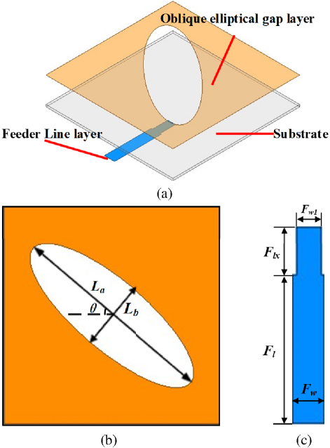
Figure 1: Geometry of the initial antenna: (a) 3D view, (b) oblique elliptical-shaped layer, and (c) feeder.
As shown in Fig. 2 (a), the initial antenna exhibits single mode resonance at 5.33 GHz with a -10 dB impedance bandwidth of 4.87.0 GHz, failing to achieve multi-mode excitation. However, a reduction in the reflection coefficient slope near 6 GHz suggests incipient mode coupling, which motivates subsequent design enhancements. Figure 2 (b) reveals that the AR remains above the 3 dB threshold across the impedance bandwidth, indicating insufficient excitation of orthogonal TM10 and TE10 modes for CP generation. The peak realized gain of 6.7 dB (occurred at 7.7 GHz) occurs outside the -10 dB impedance bandwidth.
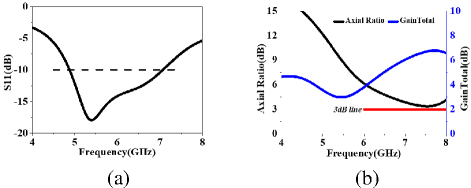
Figure 2: Simulated results of the source antenna: (a) S11 and (b) Axial Ratio and GainTotal.
To address this limitation, a 66 periodically arranged circular patch MS is integrated onto the initial antenna, with its sketch as shown in Fig. 3. The MS is fabricated on an F4BM substrate ( 2.2, tan 0.0014) and directly loaded onto the oblique elliptical slot without an intervening air gap as shown in Fig. 4 (a). Parametric sweeps in HFSS 15 optimize the MS unit cell dimensions and inter-element spacing to achieve broadband CP. The final geometric parameters are detailed in Table 1.
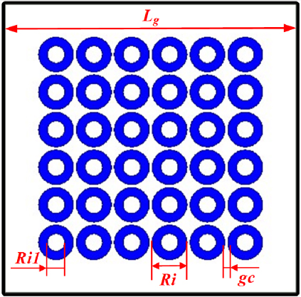
Figure 3: Sketch of the circular ring-shaped MS superstrate.
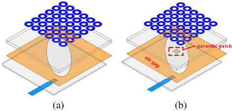
Figure 4: Geometric evolution process in the proposed antenna design: (a) Antenna 2 and (b) the proposed.
Table 1: Optimized dimensions of the proposed antenna
| Dimension | Size (mm) | Dimension | Size (mm) |
| La | 24 | Fw | 4 |
| Lb | 8 | Fw1 | 3 |
| 40deg | Lg | 50 | |
| Fl | 18.5 | L1 | 13.75 |
| Flx | 6 | Ri1 | 3 |
| Ri | 6 |
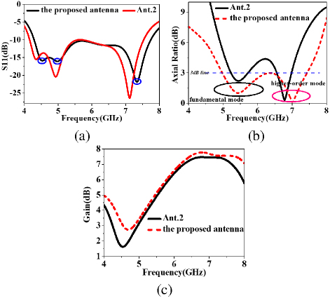
Figure 5: Comparison of the simulated results of (a) S11, (b) Axial Ratio, and (c) GainTotal in the main lobe for Ant.2 and the proposed antenna.
As depicted in Fig. 5 (a), the circular ring-shaped MS wavefront modulation capability introduces new resonance points at both high and low frequencies while shifting the original antenna’s resonance to lower frequencies. The merging of these multi-resonance modes achieves a broadband impedance bandwidth of 4.1-7.5 GHz, fully covering the C-band. Post-integration of the MS superstrate results in a global reduction of the AR within the -10 dB impedance bandwidth, with a new AR minimum of 2.2 dB emerging at 5.45 GHz. However, a mid-band AR discontinuity (4.8-5.3 GHz) hinders the formation of a continuous CP response. The gain profile demonstrates attenuation at band edges, peaking at 7.45 dBic at 7.1 GHz (a 1.45 dB improvement over the baseline design) with an average gain of 5.3 dBic across the operational bandwidth. To address the mid-band discontinuity and enhance coupling synergy between the oblique elliptical slot antenna and MS hybrid radiator, an asymmetric parasitic patch is embedded between the MS superstrate and slot layer as shown in Fig. 4 (b). This patch, offset by 1 mm along the +x-axis and separated from the lower dielectric by a 0.5 mm air cavity, disrupts structural symmetry to excite additional resonant modes. HFSS-optimized results (see Fig. 5) reveal three key outcomes. First, the third resonance shifts to higher frequencies, extending the -10 dB impedance bandwidth to 7.74 GHz (10% enhancement), while the first two resonances remain spectrally stable. Second, the AR values exhibit a maximum reduction of 6.9 dB at critical frequencies, effectively bridging the mid-band gap. The low-frequency AR minimum (2.2 dB at 5.45 GHz) remains unchanged, whereas the high-frequency minimum shifts to 7.01 GHz with an ultra-low AR of 0.1 dB, achieving a 3 dB AR bandwidth of 4.97-7.44 GHz (39.8% fractional bandwidth). Third, the air cavity reduces dielectric loss, increasing the average gain by 0.43 dB with a maximum single-frequency improvement of 1.65 dB, while maintaining stable high-frequency performance despite minor low-gain fluctuations.
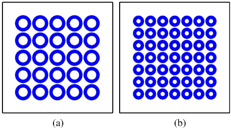
Figure 6: Two different MS layout configurations: (a) 55 and (b) 77.
To further optimize the MS layer layout configuration, the 55 and 77 periodic layouts were also simulated and analyzed. It should be noted that to evaluate performance under the same radiation aperture, the overall dimensions of all MS layers remain identical at 38.538.8 mm2, with their structures shown in Fig. 6. The simulated radiation performance for all three layouts is presented in Fig. 6.
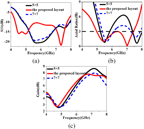
Figure 7: Radiation performance of the three MS layout configuration antenna: (a) S11, (b) Axial Ratio, and (c) GainTotal in the main lobe.
As observed in Fig. 7 (a), the 55 and 77 periodic layout configurations produce only one resonance at 5.7 GHz, whereas the proposed layout generates resonances at both low and high frequencies (5 GHz and 7.39 GHz, respectively), effectively extending the -10 dB impedance bandwidth. From Fig. 7 (b), it can be seen that the 55 and 77 periodic layouts exhibit 3 dB AR notches within the 6.2-7.2 GHz band. Although the 77 layout shows an improvement (with AR values around 4 dB within the notch frequency range), the 3 dB AR bandwidth remains discontinuous. Conversely, the 66 layout bridges the intermediate band, effectively extending the bandwidth. Regarding gain performance, as shown in Fig. 7 (c), the 55 and 77 layouts achieve peak gains higher by 1 dB and 0.5 dB, respectively, compared to the adopted layout. However, the 66 periodic layout demonstrates optimal overall performance. Therefore, this design adopts the 66 periodic layout configuration.
B. Design principles of the parasitic patch
The microstrip patch, acting as a parasitic element, is dimensionally coupled to the resonant frequency of the primary radiator, namely the oblique elliptical microstrip patch. Near-field coupling principles and geometric matching criteria are employed to optimize the parasitic patch size. Calculations based on equation (1) reveal that the standalone resonant frequency of this patch is 19.76 GHz, significantly exceeding the target operational band (4-8 GHz). This design ensures that the parasitic patch operates through cooperative near-field coupling with the primary radiator rather than relying on independent resonance.
| (1) |
The design achieves three synergistic performance improvements. First, within the 6-8 GHz band, the 6 mm patch corresponds to an electrical size of 0.16-0.21, satisfying the magnetic dipole resonance condition to enhance high-frequency radiation efficiency via inductive coupling. Second, the compact parasitic patch induces strong electric field gradients along the slot edges, refining the high-frequency phase distribution and suppressing AR degradation by balancing orthogonal field components critical for CP generation. Third, occupying only 1.44% of the primary radiator area, the patch introduces negligible obstruction to the slot’s radiation pattern, preserving radiation efficiency while enabling broadband operation.
To further validate these mechanisms, current distributions on the circular ring-shaped MS superstrate of Ant.2 and the proposed antenna were simulated at 7.0 GHz (see Fig. 8). In the proposed design (see Fig. 8 (a)), a closed-loop current distribution is observed along the major axis of the oblique elliptical slot, satisfying the necessary condition for CP radiation. Conversely, Ant.2 (see Fig. 8 (b)) exhibits dispersed peak currents along the slot’s major axis with mutually canceling vector components, failing to establish coherent current circulation for CP operation. These results demonstrate that the parasitic patch perturbs high-frequency currents and synergistically interacts with the MS to achieve phase compensation. This interaction extends the CP bandwidth while enhancing radiation efficiency, advancing conformal antenna design through a synergistic integration of near-field coupling and geometric optimization.
The parasitic patch (see Fig. 8 (a)) perturbs surface currents to form closed-loop circulation at 7 GHz, enabling coherent CP radiation. This contrasts with [18]’s metasurface-only approach, which exhibited canceling currents (see Fig. 8 (b)). Our time-domain analysis (see Fig. 9) further confirms LHCP via counterclockwise vector rotation-a physical insight absents in [18] or [19].
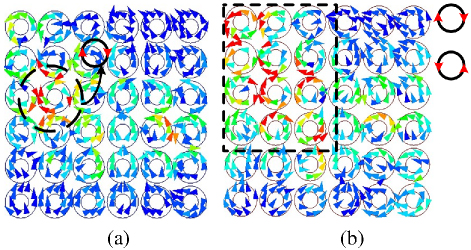
Figure 8: Current distributions on the ring-shaped MS for Ant.2 and the proposed antenna.
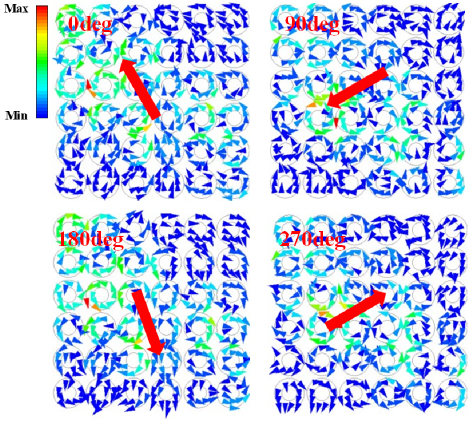
Figure 9: Surface current vectors on the MS layer at 7 GHz in one period.
To further validate the CP characteristics of the designed antenna in the high-frequency regime, a time-domain analysis of surface current vector evolution on the MS layer was conducted at 7 GHz over one full temporal cycle. As depicted in Fig. 9, at t 0, the current vector tip points to the upper-left direction. After a quarter-period interval (T/4), the vector orientation shifts to the lower-left direction. At t T/2, the vector points to the lower-right direction. At t 3T/4, it rotates to the upper-right direction. This sequential 90∘ directional change at each T/4 interval results in a counterclockwise circular trajectory of the vector tip. This rotational behavior confirms the realization of left-hand circular polarization (LHCP) radiation by the antenna, thereby experimentally verifying the effectiveness of the proposed design.
III. ANALYSIS OF CIRCULAR POLARIZATION PRINCIPLE
To validate CP performance, full-wave simulations were conducted to characterize the amplitude and phase of the far-field electric field in the circular ring-shaped MS-based oblique slot antenna. In the Cartesian coordinate system, the electric field is decomposed into two orthogonal components, Ex and Ey. Ideal CP radiation requires with a 90∘ phase difference (). For practical engineering applications, CP is considered acceptable if and
As depicted in Fig. 10, these criteria were applied to analyze Ant.2 and the proposed antenna. For Ant.2, CP operation is limited to two isolated frequency bands, namely 5.2-5.7 GHz and 6.6-6.9 GHz, with a mid-band discontinuity (4.8-5.3GHz) caused by destructive interference between Ex and Ey. In contrast, the proposed design achieves a continuous 3 dB AR bandwidth of 5.1-7.4 GHz through MS-enabled mode merging and parasitic patch coupling. This result aligns with the earlier 3 dB AR bandwidth analysis (see Fig. 5), confirming the design’s wideband CP performance.
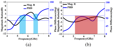
Figure 10: Simulated magnitude ratio and phase difference in the orthogonal x- and y-components of the far electric field for (a) Ant.2 and (b) the proposed antenna.
IV. RADIATING MECHANISM OF THE MS-BASED ANTENNA
To investigate the radiation characteristics of the circular ring-shaped MS (Ant.2), Figs. 11 (a,b) present simulated electric field distributions on the central vertical plane at 4.94 GHz and 7.12 GHz. Transmission-line model in Ansys Electronics Desktop is shown in Fig. 12 (a) and the dispersion characteristics of the ring-shaped unit cell, obtained through full-wave simulations, are shown in Fig. 12 (b), where the dispersion curves exhibit remarkable consistency with conventional circular microstrip units. These frequencies align with the primary and secondary resonant peaks of Ant.2 in Fig. 11 (a). Although a secondary resonance occurs at 4.4 GHz, the 4.94 GHz frequency is selected as the fundamental resonance for analytical coherence due to insufficient amplitude distinction between adjacent spectral components. For comparative analysis, theoretical predictions of TM10 and anti-phase TM20 mode distributions from rectangular patch cavity models are superimposed. The observed field patterns demonstrate topological similarity to standard patch antenna modes, with structural distinctions primarily arising from radiation gaps between IHMS cell arrays. These inter-element apertures effectively reduce the quality factor (Q) compared to conventional rectangular patches, consequently improving impedance bandwidth performance.
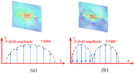
Figure 11: Simulated electric field intensity profiles along the central axis of Ant.2 corresponding to different resonant modes are presented: (a) TM10 mode at 4.94 GHz and (b) TM20 mode at 7.12 GHz, accompanied by a schematic diagram illustrating the fundamental operating principle.
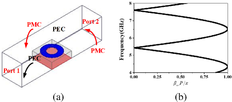
Figure 12: (a) Transmission-line model in Ansys Electronics Desktop and (b) dispersion diagrams of the circular ring-shaped MS unit cell.
Notably, surface wave propagation along Ant.2’s upper layer induces supplementary resonance mechanisms, which contribute to bandwidth enhancement. When the substrate thickness hs satisfies hs0 (free-space wavelength) and MS array dimensions meet specific constraints, the resonance behavior can be analyzed using an equivalent transmission-line model. The spatial periodicity parameters px and pygovern the x- and y-direction configurations, respectively. Mathematical expressions for TM10 and TM20 mode resonance frequencies follow the formulation detailed in reference [20], ensuring theoretical consistency with established microwave engineering principles.
An additional resonance mechanism is induced by surface wave propagation along the top layer of the Ant.2 structure, which contributes to impedance bandwidth expansion. When the substrate height (hs) is much smaller than both the vacuum wavelength and the MS array width, the resonant characteristics can be analyzed using a simplified transmission-line model. Parameters px and py denote the unit cell periodicity in orthogonal directions. The mathematical expressions for TM10 and TM20 resonant frequencies are provided in [20].
| (2) |
| (3) |
The propagation constant , in conjunction with parameters Nx and Ny denoting the number of unit cells in orthogonal dimensions (both configured as 6 in this study), serves as key determinants of the proposed antenna’s behavior. Peripheral fringing fields at the unit cell array edges introduce additional length extensions Lx and Ly in both propagation axes. The mathematical expressions for these extended lengths are detailed in equations (4)-(7).
| (4) |
| (5) |
| (6) |
Three critical parameters govern the proposed antenna’s characteristics: substrate height (hs), relative permittivity (r), and unit cell array effective width (Lp) in transverse dimensions. The propagation constants for edge-extended regions are mathematically defined in equation (6).
| (7) |
Figure 12 (b) depicts the dispersion characteristics extracted from full-wave simulation S-parameters. Antenna design employs TM modes in RH region, with theoretical TM10 and counter-phase TM20 resonant frequencies calculated as 4.9 GHz and 7.05 GHz via equations (2)-(3). Modal resonance points are identified at /0 0.055 and 0.72 on the dispersion curves. Significantly, predicted TM10 (4.94 GHz) and TM20 (7.12 GHz) resonances align closely with Ant.2’s measured 4.9 GHz and 7.12 GHz resonant peaks, demonstrating 0.8% deviation. This dispersion analysis validates the transmission-line model’s ability to explain the proposed antenna’s radiation mechanism.
V. SIMULATION ANALYSIS AND EXPERIMENTAL VALIDATION
To further validate the proposed design, the antenna prototype was fabricated and experimentally characterized. It should be noted that, during the fabrication process, a 0.5-mm air-layer was created by embedding 22 mm2 dielectric substrates (with identical electromagnetic parameters and 0.5-mm thickness) in the four corner regions of the oblique elliptical slot layer surrounding the nylon supporting pillars. This configuration forms the air cavity while maintaining structural support for the MS layer.
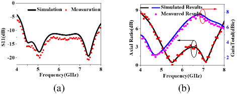
Figure 13: Simulated and measured results of the proposed circular ring-shaped MS-based antenna (a) S11 and (b) Axial Ratio and GainTotal.
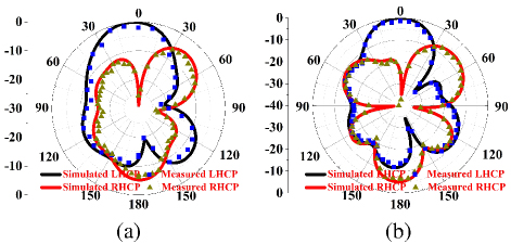
Figure 14: Normalization radiation pattern at 7 GHz in the (a) xoz plane and (b) yoz plane.
The near-field parameters were measured using a vector network analyzer, while far-field radiation characteristics were evaluated in an anechoic chamber. The experimental results are presented in Figs. 13–14. Figure 13 (a) demonstrates that the measured -10 dB impedance bandwidth extends from 4.28 GHz to 7.92 GHz, exceeding simulation predictions. The measured resonant depths show an average reduction of 1.55 dB compared with simulated results, with a maximum deviation of 2 dB, indicating excellent impedance matching performance. Figure 11 (b) reveals a 3-dB AR bandwidth from 5.06 GHz to 7.44 GHz. Although partial frequency points within 6.4-6.7 GHz approach 3 dB, the overall agreement with simulation results is favorable. The measured fractional bandwidth reaches 38%, fully contained within the -10 dB impedance bandwidth, indicating superior circular polarization radiation performance.
The measured peak gain reaches 7.61 dBic at 6.81 GHz, showing an average 0.25 dB reduction compared with simulations across the operational bandwidth, while maintaining an average gain of 5.2 dBic. Figure 14 presents the normalized radiation patterns at 7 GHz in both xoz- and yoz-planes. The measured results exhibit cross-polarization levels below -30 dB in the main beam direction, with a 3-dB beamwidth of 49∘ (-31∘ to 18∘). The radiation patterns maintain left-hand circular polarization characteristics, showing good consistency with simulated results.
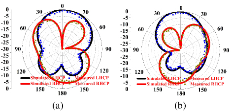
Figure 15: Normalization radiation pattern at 5.3 GHz in the (a) xoz plane and (b) yoz plane.
As shown in Fig. 15, the normalized radiation pattern at low-frequency 5.3 GHz was also analyzed. Figure 15 shows that the cross-polarization levels are consistently below -30 dB. The half-power beamwidths (HPBWs) in the E-plane and H-plane are (-52.3∘52.3∘) and (-37.7∘25.1∘), respectively, with absolute widths reaching 104.6∘ and 62.8∘. Thus, it can be observed that the proposed MS-based antenna exhibits a broader broadside radiation characteristic at low frequencies compared to high frequencies. This result consequently validates the design of the proposed MS-basedantenna.
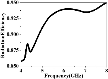
Figure 16: Simulated radiation efficiency.
As shown in Fig. 16, the radiation efficiency of the antenna was also analyzed in depth. It can be seen from Fig. 16 that the radiation efficiency within the operational bandwidth remains above 87.5%, with a maximum radiation efficiency of 93.9% occurring at 6 GHz. This demonstrates the favorable performance of the proposed MS-based antenna.
These comprehensive measurements confirm that the proposed antenna successfully achieves broadband operation, high gain, and excellent circular polarization performance, fulfilling the design objectives for advanced wireless communication systems.
VI. ANALYSIS OF THE CONFORMAL ANTENNA WITH THE DIFFERENT BENDING RADII
A. Radiation performance of conformal antenna with different bending radii
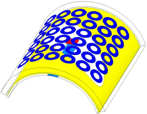
Figure 17: 3D view of the proposed MS-based conformal antenna with bending radii of 20 mm.
When the proposed antenna is subjected to bending deformation, as illustrated in Fig. 17, both the dielectric substrate and the deposited metallic patch undergo corresponding geometric transformation. This mechanical deformation induces spatial reconfiguration of the EM field distribution, thereby perturbing the radiation characteristics along the principal beam direction.
To evaluate the conformal adaptability of the proposed antenna design, radiated performance stability analysis under different radii of curvature was performed as presented in Fig. 10. The simulation results in Fig. 18 (a) demonstrate that across curvature radii of 20 mm, 30 mm, and 40 mm, the reflection coefficient maintains its resonant profile with minimal deviation in the -10 dB impedance bandwidth. Although slight variations are observed in the resonance dip depth, the integrated operational bandwidth exhibits robust stability with negligible impedance bandwidth fluctuations.
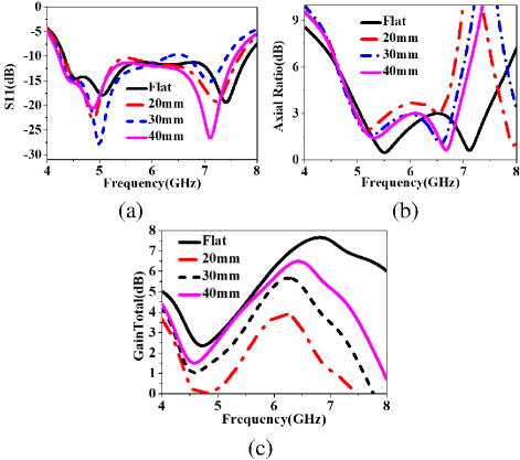
Figure 18: Antenna performance with the different bending radii: (a) S11, (b) Axial Ratio, and (c) GainTotal in the main lobe.
As shown in Fig. 18 (b), with increasing bending degree (curvature radius decreasing from 40 mm to 20 mm), the minimum AR value in the high-frequency band becomes larger, and the frequency corresponding to this minimum AR shifts toward lower frequencies after bending, with an approximate offset of 200 MHz. Meanwhile, the minimum AR values in the low-frequency band exhibit smaller fluctuations but show a slight increase compared to the flat state, with an elevation of about 0.3 dB. It can therefore be concluded that when the curvature radius ranges from 20 mm to 40 mm, the 3 dB AR bandwidth fluctuates within approximately 8.3%, indicating good stability in radiation performance after bending. Figure 18 (c) demonstrates that as the curvature radius decreases (i.e., bending intensifies), the peak gain of the main beam gradually reduces. For every 10 mm decrease in curvature radius, the peak gain decreases by approximately 1.5 dB. This occurs because the energy concentration along the main beam direction decreases when the antenna is bent, resulting in reduced peak gain. Through this analysis, it is evident that the designed antenna maintains favorable performance stability across multiple curvature radii, demonstrating good conformal capability suitable for multi-curvature platforms.
B. Analysis of the conformal antenna
Table 2: Performance comparisons with the related reported works
| Related Reported Antenna | Size (03) | S11 (GHz) | 3 dB AR Bandwidth (GHz) | Peak Gain (dBic) | Radiating Structure | Efficiency | Performance Stability in Curvature Radius Range | Technique Utilized |
| Proposed Antenna | 0.05 (height) | 4.28-7.92 | 5.06-7.44 | 7.61 | Elliptical slot + Circular ring MS + Parasitic patch | 87.5% (Peak 93.9%) | Stable (AR fluctuation8.3%, Gain drop1.5 dB/10 mm) for 20-50 mm radii | Air-layer embedded parasitic patch + Multi-curvature optimized MS |
| [18] | 4.1 1.14 0.05 | 3.95-4.8 | 3.9-4.7 (18.6%) | 5.5 | Transparent PET metasurface | 60% | Not studied | Transparent conformal metasurface |
| [19] | 0.9 0.9 0.07 | 5.02-9.12 (Free space) | 5.34-8.10 (41.07%) | 4.37 (Free space) | Hexagonal slot Nonuniform MS | 74-81% | Stable for bending (30-50 mm radii) | All-textile nonuniform MS |
| [21] | 1 1 0.1 | 4.39-7.15 | 5.43-6.76 (24.4%) | 9.35 | Slot antenna INMS | Not provided | Not studied (Planar) | Improved nonuniform metasurface (INMS) |
| [22] | Not specified | 4.3-4.6 | 4.25-4.58 (7.3%) | 11.39 | Capacitive-loaded metasurface | Not provided | Not studied | Miniaturized capacitive loading |
| [23] | 0.34 0.33 0.046 | 1.58-1.665 | 1.58-1.67 (5.5%) | 5.05 (Measured) | Triangular patches Shorting pins | Not provided | Not studied | CMA-based coupled resonators |
| [24] | Not specified | 11.2 (Resonant) | 1.6% Fractional bandwidth | 14.335 (Conformal) | Microstrip array | Not provided | Stable for vehicle roof curvature | Amplitude tapering feed |
To further illustrate the continuous decrease in main beam gain with reducing bending radius, it is recognized that as the bending radius gradually decreases, the antenna’s physical structure becomes more curved, causing the radiating surface to bend accordingly. Consequently, the field distribution in space changes. To clarify this phenomenon, a plane parallel to the antenna’s radiating surface at 10 mm distance was established for the flat state. The electric field distributions under different states were analyzed through simulation to visually reflect the electromagnetic energy distribution, with results shown in Fig. 19. Figure 19 (a) shows that when the antenna is flat, radiated energy concentrates in the main beam direction. However, when bent with a 30 mm radius, the energy distribution shifts and spreads outward. Thus, simulation results demonstrate that antenna bending causes electromagnetic energy to redistribute in space, reducing energy in the main beam direction. This results in continuously decreasing main beam energy with smaller bending radii, consistent with the gain radiation performance observed in HFSS simulations (see Fig. 18), thereby validating the design. It should be noted that, although main beam gain decreases, the circular polarization radiation characteristics and impedance bandwidth performance remain essentially unchanged.
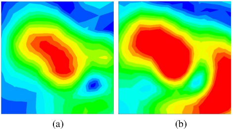
Figure 19: E-field magnitude distribution in the plane parallel to the MS at 10 mm distance: (a) flat configuration and (b) bent configuration with 30 mm radius.
VII. CONCLUSION
This paper presents a metasurface (MS) enhanced conformal circularly polarized (CP) antenna achieving broadband operation and curvature stability through three synergistic innovations. By integrating a tilted elliptical slot radiator with an annular MS superstructure, the design attains 38.7% axial ratio (AR) bandwidth via optimized modal phase compensation. A strategically embedded eccentric patch-air cavity combination extends impedance bandwidth to 42.1% (5.2-7.9 GHz) through controlled excitation of higher-order modes, while maintaining curvature-adaptive performance with 5% AR variation (AR0.25 dB) across bending radii from 10 mm to 50 mm (0.17-0.83 at 5.2 GHz). Experimental verification demonstrates 8.2 dBi peak gain and 2.4 GHz CP bandwidth, representing a 63% improvement over conventional curved CP antennas. The methodology combines characteristic mode analysis with multi-physics optimization, establishing a framework for curvature-resilient antenna design. Measured results validate the simulation-predicted performance metrics, confirming the architecture’s suitability for satellite communications and 5G systems requiring polarization-stable conformal integration. This work advances conformal CP antenna technology through its systematic fusion of MS engineering, multi-mode bandwidth enhancement, and quantified curvature compensation strategies. Future work may focus on multi-physics coupling optimization for complex curved surfaces, extension to terahertz bands, integration with reconfigurable intelligent surface for 6G, multifunctional design for biomedical applications, and fabrication process improvement via 3D printing to enhance engineering applicability.
ACKNOWLEDGMENT
This work was supported in part by the Natural Science Foundation of Hubei Province under Grant 2023AFB452.
REFERENCES
[1] K. Li, Y. Liu, Y. Jia, and Y. J. Guo, “A circularly polarized high gain antenna with low RCS over a wideband using chessboard polarization conversion metasurfaces,” IEEE Trans. Antennas Propag., vol. 65, pp. 4288-4292, 2017.
[2] H. X. Xu, Y. Shao, H. Luo, Y. Wang, and C. Wang, “Janus reflective polarization-division metadevices with versatile functions,” IEEE Trans. Microw. Theory Tech., vol. 71, pp. 3273-3283, 2023.
[3] H. Tran-Huy, H.-H. Nguyen, and T. H. T. Phuong, “A compact metasurface-based circularly polarized antenna with high gain and high front-to-back ratio for RFID readers,” PLoS One, vol. 18, no. 8, p. e0288334, 2023.
[4] S. Yang, Z. Yan, M. Cai, and X. Li, “Low-profile dual-band circularly polarized antenna combining transmitarray and reflectarray for satellite communications,” IEEE Trans. Antennas Propag., vol. 70, no. 7, pp. 5983-5992, July 2022.
[5] Z. Chen, W. Feng, Y. Yang, Y. Yu, D. Guan, and L. Sun, “Low-profile all-metal dual-band dual-polarized shared-aperture phased arrays for UAV applications,” IEEE Internet Things J., vol. 12, no. 15, pp. 31466-31476, Aug. 2025.
[6] S. Bhattacharjee, S. Maity, S. R. B. Chaudhuri, and M. Mitra, “A compact dual-band dual-polarized omnidirectional antenna for on-body applications,” IEEE Trans. Antennas Propag., vol. 67, no. 8, pp. 5044-5053, Aug. 2019.
[7] C. E. Santosa and J. T. S. Sumantyo, “Conformal subarray antenna for circularly polarized synthetic aperture radar onboard UAV,” in 2020 International Symposium on Antennas and Propagation, pp. 5-6, July 2021.
[8] D. Wu, J. Liang, and L. Ge, “A wideband dual-circularly polarized series-fed corner-truncated patch array using coplanar proximity coupling,” IEEE Trans. Antennas Propag., vol. 72, no. 4, pp. 3292-3301, Apr. 2024.
[9] Z. Hu, Q. Lin, J. Pan, and L.-H. Liang, “Slow-wave dielectric helical structure and its applications in compact omnidirectional circularly polarized antennas,” IEEE Antennas Wireless Propag. Lett., vol. 24, no. 7, pp. 1655-1659, July 2025.
[10] Z.-H. Mu, C.-X. Chen, J.-N. Ma, Y.-H. Zhao, and Q. Chen, “Wideband circularly polarized array antenna based on weakly coupled sequential phase feed network,” Microw. Opt. Technol. Lett., vol. 64, no. 1, pp. 168-173, Jan. 2022.
[11] X. Gao, L. Y. He, S. J. Yin, C. H. Wang, G. F. Wang, X. M. Xie, H. Xiong, Q. Cheng, and T. J. Cui, “Ultra-wideband low-RCS circularly polarized antennas realized by bilayer polarization conversion metasurfaces and novel feeding networks,” IEEE Trans. Antennas Propag., vol. 72, no. 2, pp. 1959-1964, Feb. 2024.
[12] T. H. Lee, J. Jung, and S. Pyo, “Circularly polarized 44 array antenna with a wide axial ratio bandwidth,” Electronics, vol. 13, no. 11, p. 2076, June 2024.
[13] X. Wang, X. Xing, Z. Zhao, J. Li, and Q. Yu, “Dual-band polarization conversion metasurface-assisted compact high-efficiency RFID reader antenna design,” IEEE Trans. Antennas Propag., vol. 72, no. 11, pp. 8810-8815, Nov. 2024.
[14] D. Ding, W. Ren, Z. Xue, and W. Li, “A low-profile spin-decoupled folded reflect array antenna with dual-circularly polarized beams,” IEEE Antennas Wireless Propag. Lett., vol. 24, no. 5, pp. 1040-1044, May 2025.
[15] S. Xu, Y. Shen, Z. Wei, and S. Hu, “Low-profile circularly polarized hybrid antenna for beam switching and OAM mode switching,” IEEE Trans. Antennas Propag., vol. 73, no. 1, pp. 33-43, Jan. 2025.
[16] X. Gao, S. Yin, G. Wang, C. Xue, and X. Xie, “Broadband low-RCS circularly polarized antenna realized by nonuniform metasurface,” IEEE Antennas Wireless Propag. Lett., vol. 21, no. 12, pp. 2417-2421, Dec. 2022.
[17] Q. Zheng, C. Guo, J. Ding, M. O. Akinsolu, B. Liu, and G. A. E. Vandenbosch, “A wideband low-RCS metasurface-inspired circularly polarized slot array based on AI-driven antenna design optimization algorithm,” IEEE Trans. Antennas Propag., vol. 70, no. 9, pp. 8584-8589, Sep. 2022.
[18] T. Liu, L. Liu, H. Sun, Z. Jin, and L. F. Chernogor, “A broadband circularly polarized antenna based on transparent conformal metasurface,” IEEE Antennas Wireless Propag. Lett., vol. 22, no. 12, pp. 3197-3201, Dec. 2023.
[19] T. T. Le, Y. D. Kim, and T. Y. Yun, “All-textile enhanced-bandwidth polarization-conversion antenna using a nonuniform metasurface,” IEEE Antennas Wireless Propag. Lett., vol. 22, no. 10, pp. 2432-2436, Oct. 2023.
[20] Q. Chen, H. Zhang, Y.-J. Shao, and T. Zhong, “Bandwidth and gain improvement of an L-shaped slot antenna with metamaterial loading,” IEEE Antennas Wireless Propag. Lett., vol. 17, no. 8, pp. 1411-1415, Aug. 2018.
[21] Q. Chen, J. Yang, C. He, L. Hong, T. Yan, F. Yu, D. Zhang, and M. Huang, “Bandwidth and gain improvement of a circularly polarized slot antenna using nonuniform metasurface,” Applied Computational Electromagnetics Society (ACES) Journal, vol. 39, no. 9, pp. 786-793, Sep. 2024.
[22] J. Yue, W. C. Yang, and W. Q. Che, “Miniaturized low-profile circularly polarized metasurface antenna using capacitive loading,” IEEE Trans. Antennas Propag., vol. 67, no. 5, pp. 3527-3532, May 2019.
[23] T. L. Yang, X. Zhang, Q. S. Wu, and T. Yuan, “Miniaturized wideband circularly polarized triangular patch antennas based on characteristic mode analysis,” Applied Computational Electromagnetics Society (ACES) Journal, vol. 38, no. 10, pp. 783-791, Oct. 2023.
[24] E. Abishek, R. Subramaniam, P. Ramanujam, and M. Esakkimuthu, “Low-profile circularly polarized conformal antenna array with side lobe suppression for vehicular SATCOM applications,” Applied Computational Electromagnetics Society (ACES) Journal, vol. 38, no. 6, pp. 439-447, June 2023.
BIOGRAPHIES

Qiang Chen was born in Jiangxi, China. He received the master and Ph.D. degree from Air Force Engineering University (AFEU), Xi’an, in 2015 and 2019, respectively. He is currently a lecturer with Air Force Early Warning Academy, Wuhan, Hubei. His research interests include microwave circuits, antennas, and arrays.

Jun Yang was born in 1973. He received his Ph.D. degree from Air Force Engineering University, Xian, China, in 2003. Now, he is an associate professor at the Air Force Early Warning Academy, Wuhan, Hubei. His research interest covers radar system, radar imaging, and compressed sensing.

Changhui He was born in 1973. She received the master’s degree from Central China Normal University, Hubei, China. She is currently an associate professor at Air Force Early Warning Institute. She is interested in electromagnetic field, microwave technology, and antenna design. She has published over 20 technical papers and authored one book. She holds four national invention patents.

Liang Hong was born in Wuhan, China. He received the B.S. and M.S. degrees from Huazhong University of Science and Technology, Wuhan, China, in 2005 and 2011, respectively. His research interests include microwave devices and microwave technology.

Di Zhang received the B.S., M.S., and Ph.D. degrees from Air Force Engineering University (AFEU), Xi’an, China, in 2013, 2015, and 2019, respectively. He is currently a lecturer with Air Force Early Warning Academy, Wuhan, Hubei. His research interests include RF orbital angular momentum antennas, reflect array antennas, and metasurface.

Li Zhang , Department of Early Warning Technology, Air Force Early Warning Academy Wuhan, Hubei, China, received his master’s degree in Radio Physics Major from Lanzhou University in 2016. His research interests mainly focus on Metamaterials and Computational Electromagnetics. He has been actively involved in several research projects related to manipulation of electromagnetic wave characteristics.

Min Huang graduated from Taiyuan University of Technology, Shanxi, China, with a master’s degree in physical electronics. She is now an instructor at the Air Force Early Warning Academy, Wuhan, Hubei. Her research interests are electromagnetic field and microwave technology.
ACES JOURNAL, Vol. 40, No. 7, 639–650
doi: 10.13052/2024.ACES.J.400708
© 2025 River Publishers