Element Failure Correction for Conformal Antenna Array Using Pre-tuned Non-Dominated Particle Swarm Optimization
Hina Munsif, Irfan Ullah, Shahid Khattak, and Shafqat Ullah Khan
1Department of Electrical Engineering
COMSATS University Islamabad, Abbottabad Campus KPK 22060, Pakistan
Hinaa3387@gmail.com, eengr@cuiatd.edu.pk, skhattak@cuiatd.edu.pk
2Department of Electronics
University of Buner, Buner, KPK 19290, Pakistan
shafqatphy@yahoo.com
Submitted On: April 21, 2025; Accepted On: July 29, 2025
ABSTRACT
This paper presents an enhanced pre-tuned particle swarm optimization (PT-PSO) algorithm for fault compensation in conformal array antennas, addressing both complete element failures and faulty phase shifters. Unlike conventional PSO, which initializes particles randomly across the entire search space (often requiring more iterations and risking local minima), PT-PSO introduces a pre-tuning mechanism that arranges initial amplitudes and phases to guide convergence. Combined with non-dominated sorting, this approach improves multi-objective optimization efficiency by reducing the search space and minimizing local minima, enabling rapid convergence to near-optimal excitation weights. To validate its effectiveness, a 18 X-band cylindrical conformal patch array was designed and simulated in HFSS. Results show that PT-PSO successfully restores first sidelobe levels (FSLL) and peak gain under both complete and partial failure scenarios, ensuring accurate pattern recovery. Compared to non-dominated PSO and convex optimization, PT-PSO achieves similar pattern quality with significantly lower computational complexity. The proposed method is particularly applicable to radar and wireless communication systems, where maintaining beam integrity under hardware faults is critical.
Index Terms: Beamforming, conformal array, PSO, sidelobe level.
I. INTRODUCTION
Maintaining a low sidelobe level (SLL) is essential for improving spatial resolution, interference rejection, and overall beamforming performance across a wide range of applications. In radar systems, low SLL reduces clutter and false alarm rates [1-2]. In communication systems, it suppresses co-channel interference and enhances signal-to-noise ratio (SNR). High-resolution imaging and precise target detection (critical in domains such as automotive radar and microwave medical imaging) also rely on tightly controlled sidelobe behavior to avoid ghost targets, imaging artifacts, and performance degradation in safety-criticalenvironments.
In beamforming phased array systems, SLL suppression and beam shaping are typically achieved through amplitude-only weighting or complex weighting (amplitude and phase). Traditional methods such as Taylor tapering and Dolph-Chebyshev distributions, as well as metaheuristic algorithms like Genetic Algorithm (GA), Particle Swarm Optimization (PSO), and Differential Evolution (DE), are commonly used to design optimal excitation weights. Conformal beamforming arrays have been adopted in diverse real-world platforms, including UAV and space vehicle communications [3], adaptive wireless communication systems [4], airborne satellite communication [5], millimeter-wave synthetic aperture radar (SAR) [6], and wearable medical imaging technologies [7].
The beamforming process in the above-mentioned systems is obtained using a transmitter/receiver module (TRM). Improper management of switching or damage to TRM (such as due to failure of CMOS transistors) can lead to faulty array antenna elements, severely affecting the performance of the communication system. When an element in the array becomes faulty, either due to complete amplitude failure (zero amplitude) or malfunctioning of phase shifter (generating random phases), it can deteriorate the entire beamforming radiation pattern. Most of the existing literature [8-13] has focused on addressing edge-element failures, where various optimization techniques are used to redistribute complex weights among working elements to recover gain, SLL, and nulls. In beamforming array systems, central elements play a more significant role in determining the gain, shaping the main beam, and controlling the first sidelobe level (FSLL). Unlike the edge elements, the center elements act as the core components of the array, carry maximum amplitudes, and significantly influence the overall performance of the radiation pattern. The random faults in central phase shifters introduce destructive interference among array elements and distort the entire array pattern. Studies [14-15] have achieved SLL and gain for the broadside and scanned patterns by calibrating phase perturbations in both edge and center elements. However, these calibration techniques require array output power measurement and depend on calibration hardware setups. The recent software techniques for pattern correction of faulty linear arrays have been reported in [16-21] and for planar arrays in [22-24]. Non-dominated PSO has been studied for conformal array in [25]. A comprehensive comparison of state-of-the-art techniques for center element failure correction, as discussed in [8-25], is presented in Table 1.
| Ref | Technique(s) Used | Recovery Type | Array Type | Findings | Limitations |
| [8-13] | GA/PSO/IFFT/PSO-CS | Amplitude-only/Complex weights | Linear/Planar/Conformal | SLL, nulls, and pattern shape recovered under random edge elements complete failure | No central complete/partial failure |
| [14-15] | Phase perturbation-based calibration | Phase-only | Arbitrary array shapes | Compensates SLL, gain, HPBW in corrected pattern due to phase perturbation | Output power measurementDependent on calibration hardware setupIneffective for complete TRM failure |
| [16] | Recursive Intelligent Optimizer (RIO) | Phase-only | Linear | Element failure detectionCorrection of SLL from -12.5 dB to -18.3 dB with 5 edge and center phase shifter failures | Limited recovery of 4-5 dB in SLLNo partial failure of central phase shiftersOnly linear arrays |
| [17] | NU-CNLMS, GA | Amplitude-only | Linear | SLL of -10 dB and null recovery under 8 edge and center failures | Limited recovery of 2-3 dB in SLLNo partial failure of central phase shiftersOnly linear arrays |
| [18] | Improved Bat Algorithm (IBA) | Complex weights | Linear | SLL of -35 dB recovery under 10 edge elements complete failureSLL of -20 dB recovered under complete failures at 3rd, 6th, 13th, 19th, 30th | Central complete failure recovery limited to -20 dBNo partial failure of central phase shiftersOnly linear arrays |
| [19] | PSO | Complex weights | Linear | Full recovery for edge element failureBeam shape recovery for central failure with SLL up to -15.5 dB | Failed to meet -20 dB target for central complete failuresNo partial failure of central phase shiftersOnly linear arrays |
| [20] | PSO, Taguchi | Complex weights | Linear | Effective edge complete failure recoveryWith central complete failure SLL to -16 dB recovered | Central complete failure recovery limited to -16 dBMain beam distortion, HPBW nearly doubled under center failureNo partial failure of central phase shiftersOnly linear arrays |
| [21] | CUSUM-based method | Amplitude-only and complex weights | Linear/Planar | Single-bit failure in edge and central attenuators and phase shiftersSLL of -25 dB (broadside), and -20 dB (scanned) recoveryHPBW recovery in planar under complete failure of 10 elements | No complete failure of central elementsDefective elements/bits position not statedNo conformal array recovery |
| [22] | GA, PSO, SA | Complex weights | Planar | Improved SNR under edge and center failures | Did not evaluate SLL, gain, HPBW, or nullsNo partial failure of central phase shiftersOnly planar arrays |
| [23-24] | GA | Phase-only | Planar | Center faulty phase shifters investigated successfully | No complete central failure |
| [25] | NS-MOPSO | Phase-only | Conformal | Center faulty phase shifters investigated successfully | No complete central failure |
| This Work | PT-PSO (Pre-Tuned PSO with Non-Dominated Sorting) | Complex weights | Conformal | SLL of -30 dB recovery under central complete failure while maintaining gain, HPBWCentral partial failed phase shifters reportedFaster convergence and more efficient than non-dominated PSO in [25] and CVX | Increased sidelobes outside mask in complete failure |
The proposed research employs a sub-optimal novel pre-tuned particle swarm optimization (PT-PSO) algorithm, which is shown to be more efficient than optimal convex (CVX) [26] and non-dominated PSO optimization algorithm [25] in terms of lower complexity and faster convergence while maintaining competitive beamforming performance. Unlike prior studies that primarily focus on edge-element failures, linear/planar geometries, or require hardware-based calibration, this work addresses a key research gap: accurate and efficient restoration of beamforming performance under central element failures in conformal arrays using purely software-based excitation optimization. The presented approach focuses solely on reconfiguring the excitations to recover the desired pattern and applicable on a wide variety of phased array systems beyond the specific antenna structure. The chosen cylindrical conformal array introduces geometric non-linearity while maintaining computational tractability, and the method is extensible to more complex array configurations. Two major issues related to the center faulty element(s) in a 18 beamforming cylindrical array have been investigated using PT-PSO: the first challenge is to recover the SLL and peak gain in the presence of a complete failure of the center elements, while the second is to restore the original pattern in the case of center faulty phase shifters. Then its performance is compared with CVX and standard PSO algorithms.
II. ELEMENT FAILURE CORRECTION USING PRE-TUNED PSO
The eight-element patch antenna array on a cylindrical conformal surface is shown in Fig. 1. The individual antenna elements are fed with attenuators (to control amplitudes) and phase shifters (to control phases) to obtain the desired beamforming array pattern. In case of any faulty attenuator/phase shifter (shown as red in Fig. 1), the desired beamforming pattern is distorted increasing the SLL and reducing the peak gain. These array parameters are severely affected in case of complete/partial failure of center elements particularly. Unlike traditional linear or planar arrays, the cylindrical conformal array used in this work introduces geometric non-linearity due to its curved surface and tilted element orientation [27]. These characteristics make beamforming control more challenging, thereby providing a more rigorous test environment for evaluating the robustness of the proposed excitation-based optimization method. The flow chart of the proposed PT-PSO for element failure correction on a conformal beamforming array is shown in Fig. 2.
The proposed PT-PSO incorporates two key enhancements: pre-tuning of the initial population and non-dominated sorting [25]. The complex excitation weight vector is expressed as:
| (1) |
where and represents the amplitude and phase on nth antenna respectively. The proposed PT-PSO begins by initializing the parameters (array size), (particles), and (maximum iterations). Corresponding to each particle and antenna element, random velocity and weight vectors are generated. These vectors can be real (for partial element failure) or complex (for complete element failure) as indicated in Fig. 2. In the next step, for the complete failure case, 10% of the population is pre tuned using standard Dolph-Chebyshev for amplitudes and compensated phase technique [28,29] for conformal arrays. After pre-tuning, the PT-PSO evaluates objective functions, updates weight vectors, and personal best and global best weight vectors following the non-dominated PSO method outlined in [25]. The objective functions reported in [25] are incorporated in the proposed PT-PSO as:
| (2) |
where represents the original reference pattern (without element failure) at the desired scan angle and is the corrected array pattern using complex weights (1) computed with PT-PSO in case of complete/partial element failure.
The PT-PSO offers significant improvements over the non-dominated PSO method by incorporating pre-tuning, which minimizes the initial population’s fitness values and reduces the computational complexity. Unlike [25], where particles are randomly distributed across the entire search space (leading to frequent trapping in local minima), PT-PSO focuses the search near optimal minima. This refinement accelerates convergence and decreases the number of iterations required.
The integration of amplitude and phase tapering techniques, along with tier-based updates for personal and global bests, allows PT-PSO to achieve faster convergence and more precise solutions for multi-objective problems. In PT-PSO, inertia weight decreases gradually from 0.6 to 0.3 over iterations to maintain precision. Unlike standard PSO, where inertia weight starts at 0.9 (allowing large exploration steps initially), PT-PSO employs pre-tuned populations with a reduced search space, requiring smaller steps to avoid leaving this space and to facilitate convergence toward the optimal solution. The cognitive parameter and social parameter are set to and .
III. RESULTS AND DISCUSSION
To evaluate the correcting pattern capability of the proposed PT-PSO, two cases of failure are investigated: (A) complete failure attenuator(s) connected to the array elements fail and therefore those amplitude(s) are considered as zero, and (B) partial failure phase shifter(s) connected to the array elements become faulty, generating random phase(s). The -30 dB FSLL and peak gain are the goals to be recovered after failures.
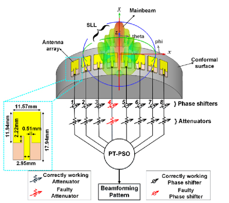
Figure 1: A 18 conformal patch array excited with attenuators and phase shifters.
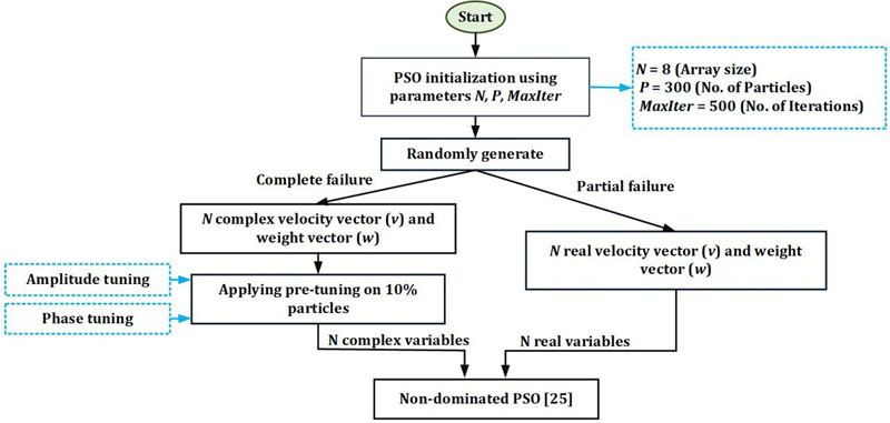
Figure 2: Flow chart for the proposed PT-PSO.
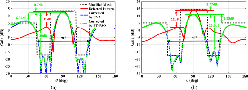
Figure 3: Simulated pattern recovery of a 18 cylindrical array with center (4th) faulty attenuator (a) MATLAB and (b) HFSS.
A. Complete failure
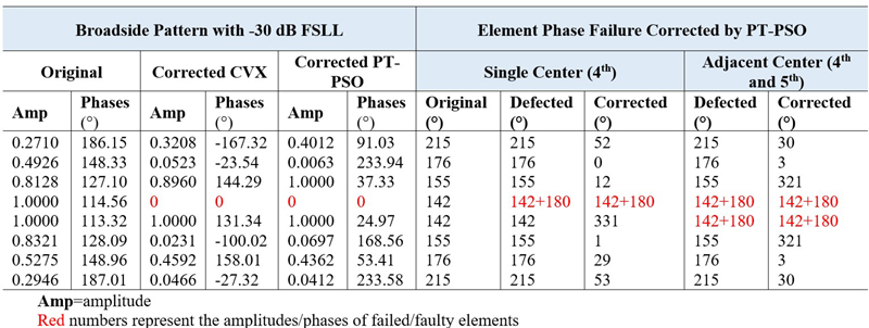
In this work, central attenuator no. 4 in Fig. 1 is assumed to be failed and its amplitude is set to zero. This choice is taken to evaluate the performance of the PT-PSO for a more critically power contributing central antenna element in generating the array pattern as compared to the edge element, where the power contribution is minimal. As shown in Fig. 3, the FSLL increases and the entire pattern is distorted due to complete failure of the central element. The mask region (-45∘ to +45∘) is applied, within which the restoration of array pattern is required for most of the real-world practical applications [29]. To compensate for the defected pattern, the PT-PSO are implemented on the faulty array to redistribute the complex weights on the remaining working elements to generate the corrected pattern that meets the criteria of the mask. The original (without failure) and PT-PSO (with failure) recalculated amplitudes/phases are reported in Table A1. As shown in Fig. 3, the recalculated weights with PT-PSO have restored the desired FSLL and peak gain within the desired mask region. As expected, the sidelobes outside the desired mask are increased. There is also a 0.7 dB difference in peak gains of the original and corrected array patterns, which cannot be recovered. For comparison, the results obtained with optimal CVX [26] are also shown in Fig. 3. Although the pattern recovering capability of optimal CVX is almost the same as the sub-optimal PT-PSO, its complexity is higher than PT-PSO. This is discussed in section IV. The original and corrected weights for complete failure are reported in Table A1.
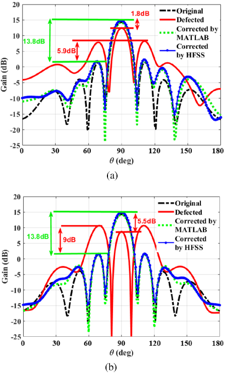
Figure 4: Simulated pattern recovery of a 18 cylindrical array with (a) single center (4th) faulty phase shifter and (b) double adjacent (4th and 5th) faulty phase shifters.
B. Partial failure
For partial failures, single and adjacent central phase shifters are considered. It is assumed that faulty phase shifter(s) can give any random value 0-2. These random perturbations in original phases causes destructive interference between the antenna element’s patterns, which deteriorates the entire array pattern. In this work, central phase shifter 4th and adjacent phase shifters 4th and 5th are considered as faulty, and a phase of is added to the original phases to demonstrate maximum deformation in the array pattern and the resulting correction capability of PT-PSO. The simulated original, defected and corrected patterns are shown in Fig. 4. As shown in Fig. 4 (a), the gain loss is 1.8 dB and increase in FSLL is 5.9 dB as compared to the original pattern due to single center element phase fault. The PT-PSO has successfully restored the main beam and FSLL to the desired pattern. The corrected phases are computed on the basis of keeping the same phase difference between antenna elements as the phase difference in original phases. This way the corrected patterns in both scenarios have exactly the same gain and FSLL as the original pattern. The case of adjacent phase shifter’s fault in Fig. 4 (b) is more severe in terms of gain drop by 5.5 dB and 9 dB increase in FSLL as compared to single phase shifter fault.
The phases recalculated with PT-PSO are able to correct the deformed pattern close to the original pattern. In double faulty phase shifters, when the fault preserves the original progressive phase, the PT-PSO-derived corrected phases successfully restores both gain and FSLL to match the original pattern. When the progressive phase is altered by the faulty phase, PT-PSO adapts by optimizing the phases of the remaining functional phase shifters, thereby reducing FSLL while maintaining the original gain, ensuring robust performance despite hardware limitations. Original and corrected weights are reported in Table A1.
To demonstrate the generality and scalability of the proposed PT-PSO algorithm, we have extended the analysis to include central element failure correction for larger conformal arrays of sizes 116, 132, 164, and 1128 as shown in Fig. 5. These results clearly illustrate that the proposed approach is effective regardless of array size. In all configurations, central elements were deliberately selected for failure to evaluate the algorithm under the most severe fault scenarios. Specifically, failures were introduced in the following elements:
18: 4th element
116: 8th and 10th elements
132: 16th, 17th, and 19th elements
164: 30th, 32nd, 33rd, and 35th elements
1128: 59th, 62nd, 64th, 65th, 67th, and 70th elements
In each case, the PT-PSO algorithm successfully restored the radiation pattern, achieving SLL-30 dB within the SLL region (-45∘ to +45∘). These results support the method’s robustness and applicability across a wide range of conformal array sizes.
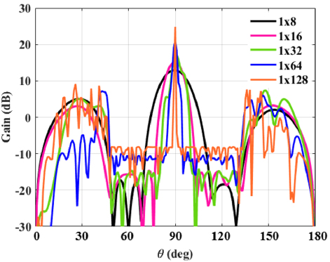
Figure 5: Center element(s) failure recovery in 1N conformal arrays.
IV. COMPUTATIONAL COMPLEXITY
In non-dominated PSO [25], the randomly generated particles are distributed across the entire search space, which contains multiple local minima. As a result, particles can become trapped in these local minima, requiring more iterations to achieve a sub-optimal solution in cases of complete/partial failure. In contrast, PT-PSO pre-tunes the randomly initialized particles by recalculating amplitude distribution similar to Dolph-Chebyshev to achieve the desired SLL and compensating the phases to achieve the main beam for failed array. This tuning process reduces the search space, thereby minimizing the number of local minima and decreasing the iterations required to reach the sub-optimal solution. The comparison between non-dominated PSO and PT-PSO is presented in Fig. 6, where both methods were initialized with the same population.
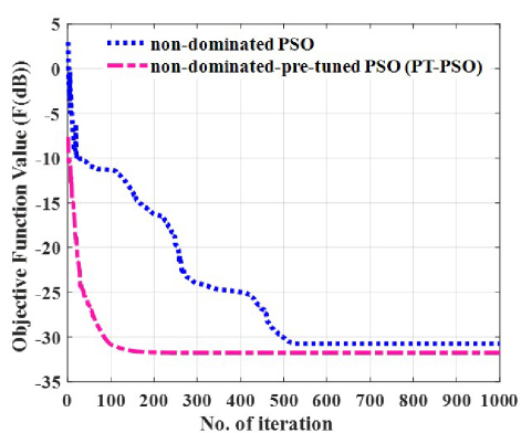
Figure 6: Objective function value () comparison with no. of iteration for non-dominated PSO [25] and proposed PT-PSO.
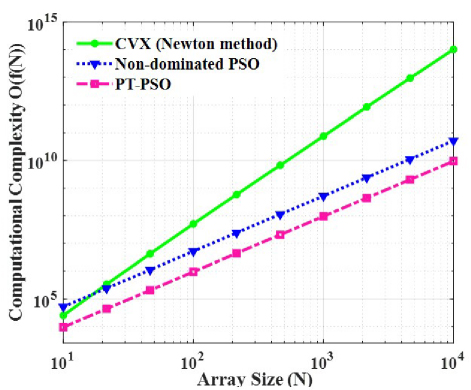
Figure 7: Computational complexity ( comparison of CVX (Newton method), non-dominated PSO [25], and PT-PSO with respect to .
For non-dominated PSO, the convergence began with an initial objective function value (F) of 2.96 dB using (II.) and reached a sub-optimal value of -30.75 dB after 529 iterations. In contrast, PT-PSO, after tuning the weight vectors, started with an initial F value of -5 dB and achieved convergence much faster, requiring only 150 iterations to reach sub-optimal F value of -31.57 dB. This demonstrates that PT-PSO not only converges more quickly but also reduces the chance of particles becoming stuck in local minima, significantly lowering the computational time by decreasing the number of iterations required.
Figure 7 compares the computational complexity of three algorithms: CVX, non-dominated PSO, and PT-PSO. The CVX algorithm employs Newton’s method to iteratively solve the Karush-Kuhn-Tucker (KKT) conditions derived from the constraints and objective functions. Newton’s method optimizes search directions and step sizes based on penalty functions, making it efficient for problems with well-structured Hessians. The computational complexity of CVX depends on the array size () and the handling of the Hessian matrix, resulting in a complexity of , primarily driven by the matrix calculations in each iteration. In contrast, non-dominated PSO and PT-PSO rely on sorting particles into Pareto-optimal tiers, with a computational complexity of for the sorting process. Consequently, their overall complexity is , where the number of iterations significantly impacts their performance. This process continues until the stopping criteria is met.
As grows, the complexity of all three algorithms increases. However, the results shown in Fig. 7 reveal that PT-PSO has the lowest complexity compared to non-dominated PSO and CVX. Particularly, CVX required 11 iterations, non-dominated PSO required 529 iterations, and PT-PSO converged in just 151 iterations. PT-PSO’s efficiently optimizes the weight vector while avoiding the computationally steep matrix operations inherent in CVX. Furthermore, PT-PSO achieves faster convergence compared to non-dominated PSO, further reducing its overall complexity. For high-dimensional problems, PT-PSO demonstrates a significant improvement in computational complexity among the three.
To benchmark the performance of the proposed PT-PSO method, a comparison is provided with widely adopted metaheuristic techniques reported in the literature, including GA [17,22-24], IBA [18], Simulated Annealing (SA) [22], and standard PSO [19-20,22,25]. These methods have been primarily applied to linear and planar arrays under various failure scenarios. As summarized in Table 1, PT-PSO achieves a SLL improvement of 21 dB, restoring the corrected SLL to -30 dB, along with enhanced main beam recovery, reduced gain loss, and faster convergence (particularly in cases involving both complete and partial failures of central elements) where traditional algorithms often degrade in performance. Additionally, the pre-tuned initialization significantly reduces computational cost, making PT-PSO highly suitable for real-world conformal array applications involving complex geometries.
V. CONCLUSION
This study presented a pre-tuned particle swarm optimization (PT-PSO) algorithm for fault compensation in conformal phased arrays, addressing both complete element failure and phase shifter faults. By combining pre-tuned initialization with non-dominated sorting, PT-PSO achieved efficient SLL and gain recovery with faster convergence and lower computational complexity than [25] and convex methods. Validation on a 18 cylindrical conformal array showed successful SLL restoration to -30 dB and minimal gain loss under severe central failures. The method is scalable to larger arrays and adaptable to conformal geometries. Its primary limitation is increased SLLs outside the constrained angular region in complete failure scenarios. Future work includes hybrid software-hardware SLL suppression using RIS, extension to complex conformal surfaces (e.g., spherical arrays), and compensation for amplifier-related nonlinearities and gain loss. These enhancements position PT-PSO as a scalable and fault-resilient solution for advanced beamforming applications in radar, communication, and medical imaging systems.
ACKNOWLEDGMENTS
This work is funded by the Higher Education Commission (HEC) Pakistan via Project No.20-17554/NRPU/R&D/HEC/2021.
REFERENCES
[1] G. Fabrizio, F. Colone, P. Lombardo, and A. Farina, “Adaptive beamforming for high-frequency over-the-horizon passive radar,” IET Radar, Sonar & Navigation, vol. 3, no. 4, pp. 384-405, 2009.
[2] Y. Xu, X. Shi, A. Wang, and J. Xu, “Design of sum and difference patterns with common nulls and low SLLs simultaneously in the presence of array errors,” IEEE Transactions on Antennas and Propagation, vol. 67, no. 2, pp. 934-944, 2018.
[3] Y. Albagory, “An efficient conformal stacked antenna array design and 3D-beamforming for UAV and space vehicle communications,” Sensors, vol. 21, no. 4, p. 1362, 2021.
[4] P. Alinezhad and S. R. Seydnejad, “Broadband adaptive beamforming of conformal arrays for wireless communications based on generalized sidelobe canceller,” Wireless Pers. Commun., vol. 96, pp. 1131-1143, 2017.
[5] H. Schippers, J. Verpoorte, P. Jorna, A. Hulzinga, A. Meijerink, C. Roeloffzen, R.G. Heideman, A. Leinse, and M. Wintels, “Conformal phased array with beam forming for airborne satellite communication,” in Proc. Int. ITG Workshop on Smart Antennas, Darmstadt, Germany, pp. 343-350, Feb. 2008.
[6] Y. Yu, Z. H. Jiang, H. Zhang, Z. Zhang, and W. Hong, “A low-profile beamforming patch array with a cosecant fourth power pattern for millimeter-wave synthetic aperture radar applications,” IEEE Trans. Antennas Propag., vol. 68, no. 9, pp. 6486-6496, Sep. 2020.
[7] F. Wang, T. Arslan, and G. Wang, “Breast cancer detection with microwave imaging system using wearable conformal antenna arrays,” in Proc. IEEE Int. Conf. Imaging Systems and Techniques (IST), Beijing, China, pp. 1-6, Oct. 2017.
[8] H. Munsif, R. A. B. Saleem, A. A. Shah, S. Khattak, A. I. Najam, B. D. Braaten, and I. Ullah, “Beamforming array failure correction for mm-wave synthetic aperture radar applications,” in Next Generation Wireless Communication: Advances in Optical, mm-Wave, and THz Technologies, M. El Ghzaoui, S. Das, V. Samudrala, and N. R. Medikondu, Eds. Cham: Springer Nature Switzerland, pp. 105-129, 2024.
[9] O. P. Acharya and A. Patnaik, “Antenna array failure correction,” IEEE Antennas and Propagation Magazine, vol. 59, no. 6, pp. 106-115, June 2017.
[10] H. Munsif, B. D. Braaten, and I. Ullah, “Sidelobe level and nulls control of defected linear antenna arrays using an optimization algorithm,” in 19th International Bhurban Conference on Applied Sciences and Technology (IBCAST), pp. 984-989, 2022.
[11] H. Munsif, B. D. Braaten, and I. Ullah, “Element failure correction techniques for phased array antennas in future terahertz communication systems,” in S. Das, N. Anveshkumar, J. Dutta, and A. Biswas, Eds. Advances in Terahertz Technology and its Applications, Singapore: Springer Singapore. pp. 19-46, 2021.
[12] H. A. Malhat, A. S. Zainud-Deen, M. Rihan, and M. M. Badway, “Elements failure detection and radiation pattern correction for time-modulated linear antenna arrays using particle swarm optimization,” Wireless Personal Communications, vol. 125, no. 3, pp. 2055-2073, 2022.
[13] B. Cao, Z. Xu, J. Yao, and T. Jiang, “Conformal array element failure correction based on PSO-CS algorithm,” in 2021 International Applied Computational Electromagnetics Society (ACES-China) Symposium, pp. 1-2, 2021.
[14] V. Djigan and V. Kurganov, “Antenna array calibration algorithm based on phase perturbation,” in IEEE East-West Design & Test Symposium (EWDTS), pp. 1-5, 2019.
[15] V. I. Djigan and V. V. Kurganov, “Antenna array calibration algorithm without access to channel signals,” Radioelectronics and Communications Systems, vol. 63, no. 1, pp. 1-14, 2020.
[16] Z. Hamici, “Fast beamforming with fault tolerance in massive phased arrays using intelligent learning control,” IEEE Transactions on Antennas and Propagation, vol. 67, no. 7, pp. 4517-4527, 2019.
[17] J. Xiaochao, P. Xu, and T. Jiang, “Comparison between NU-CNLMS and GA for antenna array failure correction,” in 2018 IEEE International Symposium on Antennas and Propagation & USNC/URSI National Radio Science Meeting, pp. 2205-2206, 2018.
[18] N. S. Grewal, M. Rattan, and M. S. Patterh, “A linear antenna array failure correction using improved bat algorithm,” International Journal of RF and Microwave Computer-Aided Engineering, vol. 27, no. 7, p. e21119, Sep. 2017.
[19] L. A. Greda, A. Winterstein, D. L. Lemes, and M. V. T. Heckler, “Beamsteering and beamshaping using a linear antenna array based on particle swarm optimization,” IEEE Access, vol. 7, pp. 141562-141573, 2019.
[20] A. M. Engroff, L. A. Greda, M. P. Magalhães, A. Winterstein, L. S. Pereira, A. G. Girardi, and M. V. T. Heckler, “Comparison of beamforming algorithms for retro-directive arrays with faulty elements,” in 2016 10th European Conference on Antennas and Propagation (EuCAP), pp. 1-5, 2016.
[21] Y.-S. Chen and I.-L. Tsai, “Detection and correction of element failures using a cumulative sum scheme for active phased arrays,” IEEE Access, vol. 6, pp. 8797-8809, 2018.
[22] N. Boopalan, A. K. Ramasamy, F. Nagi, and A. A. Alkahtani, “Planar array failed element(s) radiation pattern correction: A comparison,” Applied Sciences, vol. 11, no. 19, p. 9234, 2021.
[23] R. A. B. Saleem, A. A. Shah, H. Munsif, A. I. Najam, S. Khattak, and I. Ullah, “Pattern compensation of a planar phased array with centre elements phase malfunctioning using a genetic algorithm,” Progress in Electromagnetics Research Letters, vol. 122, pp. 21-28, 2024.
[24] R. A. B. Saleem, A. A. Shah, H. Munsif, A. I. Najam, S. Khattak, and I. Ullah, “Radiation pattern correction of faulty planar phased array using genetic algorithm,” Advanced Electromagnetics, vol. 13, no. 2, pp. 23-31, 2024.
[25] H. Munsif and I. Ullah, “Malfunctioning conformal phased array: Radiation pattern recovery with particle swarm optimisation,” IET Microwaves, Antennas & Propagation, vol. 18, no. 9, pp. 654-666, 2024.
[26] S. Boyd, Convex Optimization. Cambridge: Cambridge University Press, 2004.
[27] I. Ullah, H. Munsif, S. Razzaq, and A. I. Najam, “Cylindrical phased array with adaptive nulling using eigen-correlation technique,” International Journal of RF and Microwave Computer-Aided Engineering, vol. 32, no. 2, p. e22969, 2022.
[28] R. L. Haupt, Antenna Arrays: A Computational Approach. Hoboken, NJ: John Wiley & Sons,2010.
[29] M. Li, S.-L. Chen, Y. Liu, and Y. J. Guo, “Wide-angle beam scanning phased array antennas: A review,” IEEE Open Journal of Antennas and Propagation, vol. 4, pp. 695-712, 2023.
APPENDIX
Table A1: Optimized excitation weights (amplitude/phase and phase-only) for complete and partial element failures using PT-PSO and CVX algorithms
BIOGRAPHIES

Hina Munsif holds a bachelor’s degree in Electrical (Communication) Engineering in 2015 from the University of Engineering and Technology Peshawar, KPK, Pakistan, and a master’s degree in Electrical Engineering in 2020 from COMSATS University Islamabad, Abbottabad Campus, Pakistan. She is currently pursuing a Ph.D. degree in Electrical Engineering from COMSATS University Islamabad, Abbottabad Campus. Her research interests include antenna arrays for 6G-and-beyond communication and IoT.

Irfan Ullah received a Ph.D. degree in Electrical and Computer Engineering from North Dakota State University, Fargo, ND, USA, in 2014. He is an Associate Professor in Electrical Engineering Department at COMSATS University Islamabad, Abbottabad Campus, Pakistan. His research interests include beamforming arrays, machine learning in antenna arrays, electromagnetic metamaterials and topics in EMC.

Shahid Khattak received Dr.-Ing degree from Technische Universität Dresden, Germany, in 2008. He is a distinguished academic and researcher specializing in electrical and computer engineering, with a focus on advanced communication systems, signal processing, and applied electromagnetics. He has contributed extensively to both theoretical and applied research, with numerous publications in reputed international journals. Khattak is known for his dedication to academic excellence and mentoring, and he plays a pivotal role in advancing interdisciplinary research in engineering and technology.

Shafqat Ullah Khan received M.S. and Ph.D. degrees in Electronic Engineering from International Islamic University Islamabad and ISRA University, Pakistan, in 2008 and 2015, respectively. He was a Post Doc Fellow at the Faculty of Electrical Engineering, University Technology Malaysia from 2016 to 2017. He is an Associate Professor at the University of Buner. His research interest includes RF & microwave, antenna arrays and evolutionary algorithms.
ACES JOURNAL, Vol. 40, No. 8, 714–723
doi: 10.13052/2024.ACES.J.400804
© 2025 River Publishers