Dual-Polarized, Low-RCS Wideband Fabry-Pérot Antenna Utilizing a 3D-Printed Stepped Absorbing Structure
Zhixin Lei1, Zhiming Liu1, Hao Xu1, Huilin Zhou1, Fei Wang2, and Yuxuan Huang1
1School of Information Engineering Nanchang University, Nanchang 330031, China
zhixinlei2001@163.com, zhimingliu@ncu.edu.cn, xuhao_0805@163.com, zhouhuilin@ncu.edu.cn, yuxuanhuang2002@163.com
2Fujian Key Laboratory of Special Energy Manufacturing Huaqiao University, Xiamen 361021, China
wangfei@hqu.edu.cn
Submitted On: April 24, 2025 Accepted On: August 21, 2025
Abstract
A dual-polarized Fabry-Pérot (FP) antenna with ultra-wideband radar cross section (RCS) reduction using 3D printing technology is proposed. The proposed antenna consists of a dual-polarized primary antenna and a partially reflective surface (PRS) loaded with reflective surface (RS) and 3D-printed stepped absorbing structure (3D-PSAS). The combination of the RS and the 3D-PSAS effectively reduces the RCS of the FP antenna and maintains the gain of the antenna. Meanwhile, the proposed antenna can be used in the construction of stealth systems. Both the simulated results and the measured results verify the reliability of the design. The FP antenna owns 10-dB RCS reduction bands cover 3.03.8 GHz and 615 GHz, with a peak RCS reduction of 27 dB at 12.5 GHz. In the radiation, it owns a 10-dB return-loss bandwidth of 4.64–5.64 GHz (19.4%) and 4.76–5.61 GHz (16.3%) respectively in X polarization and Y polarization modes, with a maximum realized gain of 12.4 dBi at 4.9 GHz.
Keywords: 3D printing technology, Fabry-Pérot antenna, partially reflective surface, radar cross section..
1 INTRODUCTION
Fabry-Perot (FP) antennas are widely used in satellite communications, radar, stealth platforms, wireless communications and other fields due to their high gain, strong directivity, planar structure, compactness and light weight [1, 2, 3, 4, 5]. Its flexible design optimizes wideband performance, circular polarization, high gain, and low radar scattering area (RCS). Low-RCS is crucial for enhancing the stealth capabilities of military equipment and improving the performance of communication systems. It plays a significant role in reducing signal leakage and interference, ensuring the stability and reliability of communication systems. However, in the process of reducing RCS using a radome or metasurface, the commonly employed structure involves a combination of metal and dielectric substrate, which limits the bandwidth of RCS reduction. Moreover, FP antennas can be reconfigured for various purposes such as frequency reconfiguration [6, 7], polarization reconfiguration [8], radiation pattern reconfiguration [9], and RCS reduction reconfiguration [10].
In recent years, an increasing number of researchers have turned their attention to the study of antennas with reduced RCS. In order to reduce the RCS of the antenna and improve its deployment capability on stealth platforms, various design methods have been proposed, including polarization conversion metasurfaces (PCMs) [11, 12, 13], hybrid reflection methods [14], coding metasurfaces [15], artificial magnetic conductors (AMCs) and absorbing surfaces (ASs) [16, 17, 18, 19]. The PCM effectively realizes the in-band RCS reduction of the FP antenna through phase cancellation, which improves the gain bandwidth while maintaining good RCS rejection performance. However, the RCS reduction effect of this method in broadband is still not ideal, which limits its application in stealth antennas. Moreover, AMCs and ASs provide effective absorption of incident waves and reduce RCS in a broader frequency range [16]. However, they absorb a large amount of radiation energy of antennas. Consequently, simultaneously achieving both broadband RCS reduction and antenna gain improvement in an antenna remains a challenging task.
Meanwhile, 3D printing technology, owing to its capability of fabricating complex structures, is increasingly applied in the design of multifunctional antennas. Many researchers are using 3D printing technology to design different kinds of antennas, such as circularly polarized antennas [20, 21], dual-polarized antennas, array antennas [22], Yagi-Uda antennas [23], resonant cavity antennas [24], and lens antennas [25]. It has also been employed in designing complex electromagnetic structures like circuits [26], frequency selective surfaces [27], and absorbers [28]. This application of 3D printing has broadened the possibilities for developing innovative antenna systems and electromagnetic devices [29].
A low-RCS dual-polarized FP antenna based on a partially reflective surface (PRS) using 3D printed technology is proposed here. The PRS of the proposed antenna combines a 3D-printed stepped absorbing structure (3D-PSAS) with a reflective surface (RS). Firstly, the RS is positioned above a dual-polarized primary antenna at an appropriate height. By utilizing the reflection characteristic of the RS, a simple FP resonant cavity between PRS and ground is formed, which concentrates the radiation energy of the antenna. The 3D-PSAS utilizes 3D printing technology to process absorbing materials into stepped gradient structures that help to reduce RCS. A dual-polarized slot patch antenna is used as the primary antenna, which switches the polarization mode by regulating the voltage at both ends of the PIN diode. According to the simulation and measured results, the proposed antenna not only significantly reduces the RCS and covers the ultra-wide band but also enhances the realized gain. RCS peak reduction is 27 dB.
2 DESIGN OF FABRY-PÉROT ANTENNA
A FP antenna possesses the characteristics of high gain and concentrated radiation energy. Its main performance indicators include operating frequency, gain, radiation pattern, and bandwidth, which depend on the reflection phase of PRS and the height of the resonator cavity of the FP antenna. The above performance indicators meet the following formula [30]:
| (1) |
where and are the reflection phases of PRS and ground, respectively, c is the speed of light, is the cavity height of the FP antenna resonator, f is the resonance frequency of the FP antenna, N is the number of times that the electromagnetic waves excited by the antenna are reflected between PRS and ground. In this design, . The electromagnetic waves emitted by the main antenna oscillate several times in the resonator. When the reflection phase of the PRS satisfies Equation (2), a standing wave pattern is formed, which excites the FP resonance to enhance the directivity and gain of the antenna.
2.1 Partially reflective surface
In the proposed antenna, the PRS is composed of a RS and 3D-PSAS, as shown in Fig. 1. The RS adopts a double-layer structure design, with a square metal patch with a length of on one side and a circular square ring structure with an inner diameter of at the bottom. These patches are printed on either side of the F4BM265 (, ) dielectric substrate. It is used to form a FP resonant cavity between PRS and ground. In addition, 3D-PSAS is a metamaterial structure that sits on top of the RS and is designed with three layers of stepped square holes, each with layer height of , and to achieve a gradient electromagnetic absorption characteristic. In order to achieve better absorption performance, the metamaterial is composed of 4% carbon black and 250% carbonyl iron powder, which can comprehensively utilize their respective advantages and enhance the dielectric properties and magnetic properties of the material, absorb electromagnetic waves transmitted from RS and reduce RCS. Adjusting the stepped gradient structure of 3D-PSAS can change the selective transmittance of PRS and flexibly adjust the frequency band of RCS reduction. Therefore, the simulation results of the reflection coefficient of 3D-PASA with three different height parameter changes are given. This is shown in Fig. 2. At the same time, this adjustment decreases the extent to which electromagnetic waves emitted by the primary antenna are absorbed. The parameters of the optimized PRS unit structure are shown in Table 1.
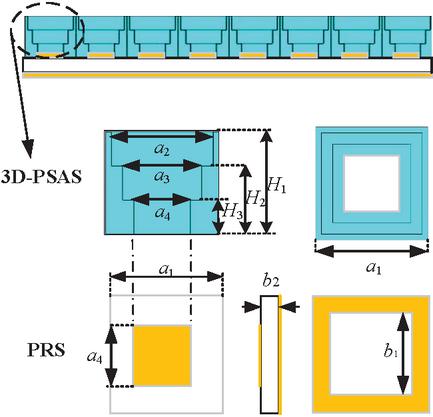
Figure 1 Schematic of the PRS.
Table 1 Design parameters of the PRS
| Parameter | |||||
| Value (mm) | 9 | 6 | 3 | 10 | 9 |
| Parameter | |||||
| Value (mm) | 7 | 5 | 7 | 1.5 |
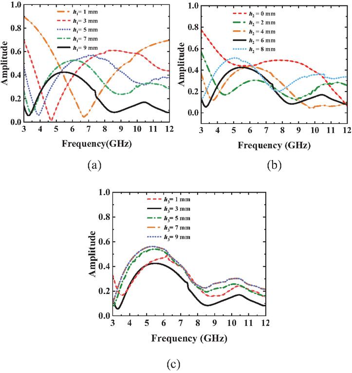
Figure 2 Effect of each parameter on the Port 1 reflection coefficient of 3D-PSAS. (a) , (b) , (c) .
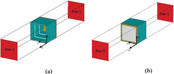
Figure 3 Simulated model of the PRS unit: (a) top and (b) bottom.
In this design, the model was simulated using CST Microwave Studio 2022 version, using a time-domain solver and global meshing, with a maximum grid element size of 1 mm and an S-parameter convergence accuracy of 40 dB. The PRS model design and simulation settings are as follows. In Fig. 3, Port 1 and Port 2 are located at fixed distances on either side of the PRS unit. To simulate the PRS unit structure, the x directions are set as electric wall boundary conditions, while the y directions are set as magnetic wall boundary conditions.
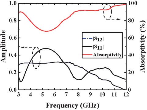
Figure 4 S11, S12, and absorptivity of the PRS.
Figure 4 depicts the simulated results of the PRS unit. The diagram illustrates the reflection coefficient (S11) and transmission coefficient (S12) of the PRS and depicts the absorption characteristics of the PRS for electromagnetic waves using the absorptivity. is the absorptivity of the PRS, which can be calculated by:
| (2) |
As shown in Fig. 4, the PRS has an absorptivity of greater than 67% but lower than 80% within the frequency range 3.90–6.50 GHz. It indicates that the absorption ability of 3D-PSAS has a relatively small impact on the antenna radiation within the operating band of the antenna. However, outside this frequency band, the PRS shows excellent wave absorption performance, with the absorptivity higher than 80%. which effectively attenuates the energy of the incident wave and reduces the RCS.
2.2 Primary antenna
As shown in Fig. 5, a dual-polarized slot antenna with parasitic patch acts as the primary antenna. The antenna is fed through a microstrip line that is patterned on the underside of the substrate. The parasitic patch is an F4BM265 dielectric substrate printed with a square metal length , which can expand the bandwidth of the primary antenna. It is placed above the primary antenna at . On the surface of the dual-polarized antenna, a metal ground plane is etched. Two H-shaped coupling slots are formed on this plane to achieve the dual-polarization characteristics of the antenna. The specifications for the primary antenna’s design are provided in Table 2.
The polarization mode of the primary antenna is determined by the states of the Pin 1 and Pin 2 diodes. These diodes can be controlled by changing the voltage levels at both ends of the diode using wires. The antenna radiates y-polarization (YP) waves as the Pin 1 diode is turned on and the Pin 2 diode is turned off. The antenna radiates x-polarization (XP) waves as the Pin 2 diode is turned on and the Pin 1 diode is turned off. By switching between these two states, the electromagnetic waves radiated by antennas can be converted between XP and YP, allowing for adaptable communication and reception capabilities.
The simulated results for the primary antenna are presented in Fig. 6. These results demonstrate that when the antenna radiates YP waves, its 10-dB impedance bandwidth ranges from 4.83 to 5.70 GHz, which corresponds to a relative bandwidth of 16.5%. The primary antenna achieves a maximum realized gain of 8.70 dBi at a frequency of 5.50 GHz. Comparison of simulated results of YP and XP show similar operating bandwidths and realized gains, except for differences in polarization states. The primary antenna works within the frequency band of 4.83 to 5.70 GHz, during which the 3D-PSAS exhibits lower absorptivity, minimizing the effect of the 3D-PSAS on the FP antenna’s radiation performance.
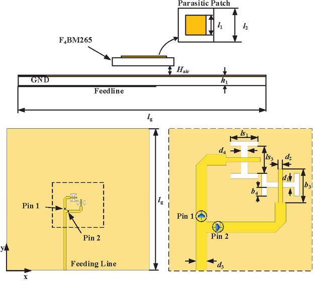
Figure 5 Schematic of the primary antenna.
Table 2 Design parameters of the primary antenna
| Parameter | |||||
| Value (mm) | 30 | 17.7 | 1.2 | 1 | 2.5 |
| Parameter | |||||
| Value (mm) | 5.2 | 6.2 | 7.7 | 2 | 1.4 |
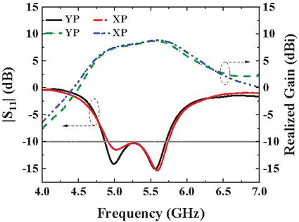
Figure 6 S11 and realized gain of primary antenna.
3 FABRY-PÉROT ANTENNA USING 3D-PRINTED STEPPED ABSORBING STRUCTURE
After analyzing the unit of the PRS and the primary antenna, a unit structure with a length and width of 10 mm is designed. The structure of the 3D-PASA is originally designed as a array, with specific RS having dimensions of . In addition, the four corners of the 3D-PSAS are adjusted to a rectangular shape with a height of 5 mm. Cylindrical holes are incorporated in these modified corners to facilitate fixation using nylon screws. The simulated results indicate that this modification has minimal impact on the antenna performance. As depicted in Fig. 7, the 3D-PSAS is installed at a fixed elevation above the primary antenna.
The key to FP resonant excitation lies in the reasonable design of the height of the antenna resonator. Based on Equation (2), the initial reference height is calculated, and the parameter sweep and performance analysis are carried out in its neighborhood, and the optimal cavity height is determined to be mm by considering the 10 dB impedance bandwidth and antenna gain holistically.
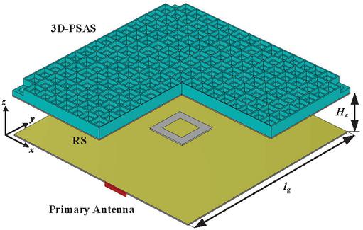
Figure 7 Proposed FP antenna with 3D-PSAS.
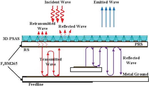
Figure 8 RCS-reduced FP antenna working schematic.
In Fig. 8, the mechanism for decreasing RCS and improving gain of the FP antenna is depicted. When the incident waves enter the cavity through PRS, a portion of the energy of the incident wave is absorbed by 3D-PSAS, while another portion passes through 3D-PSAS and becomes transmitted waves. These transmitted waves experience repeated reflections between the metallic ground plane and the PRS. Part of the transmitted waves are transmitted out of the antenna through the bottom of the PRS and becomes the retransmitted waves. The others continue to reflect and transmit within the cavity. The proposed antenna achieves ultra-wideband RCS reduction by absorbing incident waves through the 3D-PSAS layer.
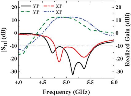
Figure 9 S11 and realized gain of FP antenna.
Figure 9 displays the simulated S11 and the realized gain of the proposed FP antenna under YP and XP. The proposed antenna, when operating under YP, exhibits a 10-dB impedance bandwidth ranging from 4.64 GHz to 5.64 GHz (19.4%) and a peak realized gain of 12.40 dBi at 4.90 GHz. Comparing the proposed FP antenna with the primary antenna, the 10-dB impedance bandwidth is slightly reduced and the maximum realized gain is increased from 8.7 dBi to 12.4 dBi. The proposed antenna under XP has a 10-dB impedance bandwidth of 4.76–5.61 GHz (16.3%) and a maximum realized gain of 12.4 dBi at 5.2 GHz. The 10-dB impedance bandwidth and gains of the proposed FP antenna varies between YP and XP. This difference is due to the inconsistent widths of the H-shaped slots designed for each polarization. Compared with the primary antenna, the performance comparison shows that the polarization characteristics have not changed significantly.
In addition, in terms of antenna efficiency, the analog efficiency of the antenna at the operating frequency center (5.14 GHz) is 64% after the PRS is added above the feed. It is 59% after loading the absorbing structure, which is due to its effect on the absorption of electromagnetic waves. In addition, the antenna has an aperture efficiency of 45.1% at 5.14 GHz.
4 EXPERIMENTAL RESULTS
Figure 10 shows a physical image of the antenna using 3D printing technology. The measurement scene is shown in Fig. 11.
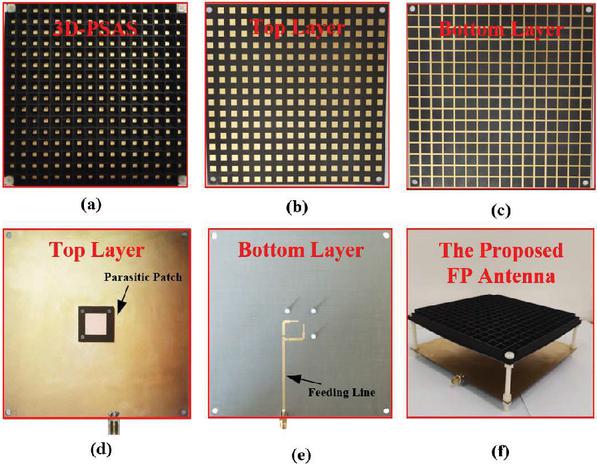
Figure 10 FP antenna using 3D printing technology: (a) top layer of 3D-PSAS, (b) top layer of RS, (c) bottom layer of RS, (d) top layer of primary antenna, (e) bottom layer of primary antenna, (f) FP antenna.
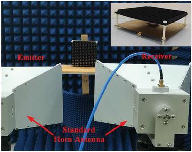
Figure 11 Measurement scene of the FP antenna.
Figure 12 presents a comparison between the simulated and measured results of the primary antenna in both YP and XP states. It indicates that the primary antenna exhibits measured 10-dB impedance bandwidths ranging from 4.83–5.70 GHz for YP and 4.91–5.70 GHz for XP. Additionally, the maximum realized gain achieved is 8.71 dBi at 5.5 GHz under YP, and 8.80 dBi at 5.6 GHz under XP. Under YP, the measured results of resonant frequency are generally shifted to higher frequencies compared to the simulated results. This phenomenon is primarily due to the error when installing the antenna, and the error causes the height of the parasitic patch to change. When the height of the parasitic patch is decreased, the resonant frequency of the primary antenna shifts towards higher frequencies.
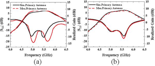
Figure 12 Comparison of measured and simulated results of the primary antenna: (a) YP, (b) XP.
From Fig. 13, it can be seen that the measured results of the FP antenna loaded with 3D-PSAS generally conforms to the simulated results. Under YP, it shows that the FP antenna has a measured 10-dB impedance bandwidth of 4.60 to 5.63 GHz (20.1%), a measured 3-dB gain bandwidth of 4.60 to 5.30 GHz (14%), and a measured maximum realized gain of 12.5 dBi at 4.9 GHz. Shown in Figs. 13 (c,d), under XP, the proposed FP antenna possesses a measured 10-dB impedance bandwidth of 4.70–5.60 GHz (17.4%) and a measured maximum realized gain of 12.6 dBi at 5.0 GHz.
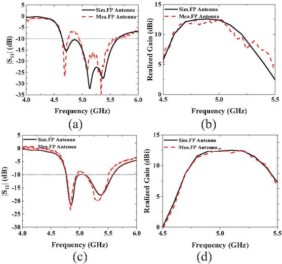
Figure 13 Comparison of the measured and simulated results of the FP antenna: (a) -YP, (b) realized gain-YP, (c) -XP, (d) realized gain-XP.
Figure 14 presents the E-plane radiation patterns, both simulated and measured, at frequencies of 4.7 GHz and 5.0 GHz for YP and XP. As can be seen from Fig. 14, the sidelobe level decreases significantly relative to the direction of the main beam and is basically below 0 dB. This result fully shows that the proposed antenna exhibits excellent radiation performance in the whole operating frequency band.
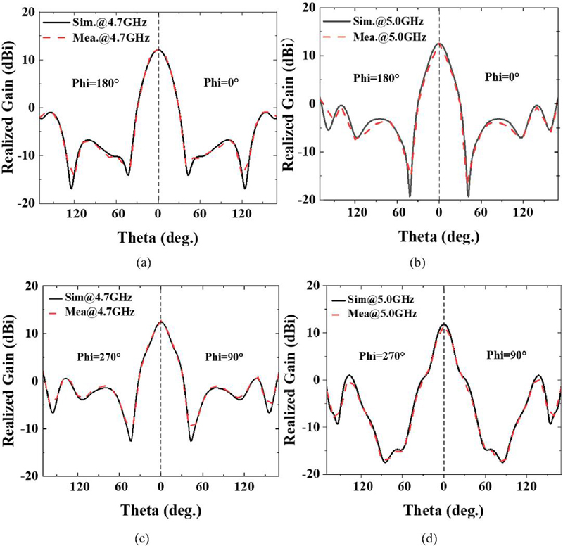
Figure 14 Radiation patterns of the proposed antenna: (a) 4.7 GHz-YP, (b) 5.0 GHz-YP, (c) 4.7 GHz-XP, (d) 5.0 GHz-XP.
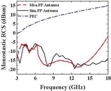
Figure 15 Simulated RCS reduction and measured RCS reduction of the proposed antenna.
Figure 15 shows the measured results and simulated results of the monostatic RCS curves for the designed antenna. It can be observed that the measured RCS of the FP antenna decreases within the range of 3–18 GHz, with a peak reduction of 27 dB at 12.5 GHz. In addition, it can be seen from the measured results that the proposed antenna exhibits bandpass filter characteristics. In the frequency range of 4.6–6.4 GHz, the monostatic RCS of the proposed antenna is higher than 10 dB, so that more electromagnetic waves can radiate out of the antenna through 3D-PSAS. The proposed antenna is capable of achieving higher realized gain. Due to the lack of test environment, the aging of the performance of the test device and the error of antenna processing, the measurement results and the simulation results have changed slightly, but the trend is basically the same.
Table 3 lists other works that have used AMC, ASs, and other methods to reduce RCS. Comparison shows that this work has a wide 10-dB RCS reduction band and good radiation performance. The test results closely match the simulation results, thereby validating the feasibility and effectiveness of this work.
5 CONCLUSION
A low-RCS dual-polarized FP antenna based on 3D-PSAS is proposed. By comparing the simulated and measured results, it has been demonstrated that the 3D-PSAS can effectively achieve ultra-wideband RCS reduction for the FP antenna. The PRS of the proposed antenna consists of the RS and the 3D-PSAS which was produced using 3D printing technology. The reflection performance and absorption performance of the antenna are optimized through analysis. The antenna has a maximum gain of 12.4 dBi at 4.9 GHz and a maximum RCS reduction of 27 dB at 12.5 GHz. The measured results show that the 10-dB impedance matching bandwidths of the proposed FP antenna are 19.7% and 16.2% in YP and XP, and RCS reduction bandwidth of 3.0–3.8 GHz and 7.3–18 GHz under different polarization modes. The antenna can be useful in the construction of stealth communication systems.
Table 3 Comparison between the proposed antenna and existing works
| Ref. | Method | Feed Type | 10-dB | Max | 10-dB | Max | Area () |
| Impedance | Realized | RCS | RCS | ||||
| Bandwidth | Gain | Reduction | Reduction | ||||
| (GHz) | (dBi) | Band (GHz) | Value (dB) | ||||
| [15] | Coding | Horn antenna | N.A. | N.A. | 9.26–12.87 | 19 | N.A. |
| Metasurface | 14.84–19.35 | ||||||
| [17] | AMC | Whip antenna | N.A. | N.A. | 8.0–12.0 | 22 | 0.5, 0.67, 0.83 |
| [18] | AMC-FSS | MAs-loading antenna | 4.25–5.42 (24%) | 11.13 | 8.2–18.0 | 35 | |
| [19] | AS | Circularly polarized patch antenna | 10.50–10.78 (2.6%) | 10.2 | 8.0–12.0 | 27.6 | |
| This Work | 3D-PSAS | Dual-polarized slot antenna | 4.60–5.40 (16%) | 12.40 | 3.0–3.8 6.0–18.0 | 27 | |
| Note: denotes the wavelength of the center frequency of the effective bandwidth in free space. |
ACKNOWLEDGMENT
This research was supported in part by the National Natural Science Foundation of China (Grant No. 62201240, 62161027, 71961017), in part by Jiangxi Provincial Natural Science Foundation (Grant No. 20224BAB212005), in part by open research project of the science and technology innovation platform (Huaqiao University) of Fujian Key Laboratory of Special Energy Manufacturing (No. FKLSEM-2022-04), in part by Jiangxi Provincial Key Laboratory of Intelligent Systems and Human-Machine Interaction (2024SSY03121).
REFERENCES
[1] Y. Sun, Z. N. Chen, Y. Zhang, H. Chen, and T. S. P. See, “Subwavelength substrate-integrated Fabry-Pérot cavity antennas using artificial magnetic conductor,” IEEE Trans. Antennas Propag., vol. 60, no. 1, pp. 30–35, 2012.
[2] Y. Zheng, J. Gao, Y. Zhou, X. Cao, H. Yang, and S. Li, “Wideband gain enhancement and RCS reduction of Fabry-Perot resonator antenna with chessboard arranged metamaterial superstrate,” IEEE Trans. Antennas Propag., vol. 66, no. 2, pp. 590–599, 2018.
[3] M. W. Niaz, Y. Yin, R. A. Bhatti, Y.-M. Cai, and J. Chen, “Wideband Fabry-Perot resonator antenna employing multilayer partially reflective surface,” IEEE Trans. Antennas Propag., vol. 69, no. 4, pp. 2404–2409, 2021.
[4] W. Wang and Y. Zheng, “Wideband gain enhancement of high-isolation Fabry-Pérot antenna array with tandem circular parasitic patches and radial gradient PRS,” IEEE Trans. Antennas Propag., vol. 69, no. 11, pp. 7959–7964, 2021.
[5] Z. Liu, J. Bornemann, D. F. Mamedes, S. Liu, X. Kong, and X. Zhao, “A wideband Fabry-Pérot antenna with enhanced gain in the high-frequency operating band by adopting a truncated field correcting structure,” IEEE Trans. Antennas Propag., vol. 69, no. 12, pp. 8221–8228, 2021.
[6] C. J. You, S. H. Liu, J. H. Zhang, X. Wang, Q. Y. Li, and G. Q. Yin, “Frequency- and pattern-reconfigurable antenna array with broadband tuning and wide scanning angles,” IEEE Trans. Antennas Propag., vol. 71, no. 6, pp. 5398–5403, 2023.
[7] C. Huang, W. Pan, X. Ma, and X. Luo, “A frequency reconfigurable directive antenna with wideband low-RCS property,” IEEE Trans. Antennas Propag., vol. 64, no. 3, pp. 1173–1178, 2016.
[8] J. Yang, S.-S. Qi, W. Wu, and D.-G. Fang, “A Fabry-Perot conical beam antenna with multi-polarization reconfigurable capability,” IEEE Trans. Antennas Propag., vol. 70, no. 11, pp. 11091–11096, 2022.
[9] X. Yang, Y. Liu, H. Lei, Y. Jia, P. Zhu, and Z. Zhou, “A radiation pattern reconfigurable Fabry-Pérot antenna based on liquid metal,” IEEE Trans. Antennas Propag., vol. 68, no. 11, pp. 7658–7663, 2020.
[10] Y. Wang, Z. Liu, H. Zhou, J. Bornemann, Y. Wang, and X. Kong, “A high-gain wideband Fabry-Pérot antenna employing a water-based frequency selective surface for polarization- and RCS-reconfigurability,” Int. J. RF Microw. Comput. Aided Eng., vol. 2024, no. 1, p. 1804375, 2024.
[11] K. Li, Y. Liu, Y. Jia, and Y. J. Guo, “A circularly polarized high-gain antenna with low-RCS over a wideband using chessboard polarization conversion metasurfaces,” IEEE Trans. Antennas Propag., vol. 65, no. 8, pp. 4288–4292, 2017.
[12] J. Liu, J.-Y. Li, and Z. N. Chen, “Broadband polarization conversion metasurface for antenna RCS reduction,” IEEE Trans. Antennas Propag., vol. 70, no. 5, pp. 3834–3839, 2022.
[13] H. Dai, Y. Zhao, and C. Yu, “A multi-elements chessboard random coded metasurface structure for ultra-wideband radar cross section reduction,” IEEE Access, vol. 8, pp. 56462–56468, 2020.
[14] Z. Liu, S. Liu, X. Zhao, X. Kong, Z. Huang, and B. Bian, “Wideband gain enhancement and RCS reduction of Fabry-Perot antenna using hybrid reflection method,” IEEE Trans. Antennas Propag., vol. 68, no. 9, pp. 6497–6505, 2020.
[15] C. Fu, L. Han, C. Liu, X. Lu, and Z. Sun, “Combining Pancharatnam-Berry Phase and conformal coding metasurface for dual-band RCS reduction,” IEEE Trans. Antennas Propag., vol. 70, no. 3, pp. 2352–2357, 2022.
[16] M. Paquay, J.-C. Iriarte, I. Ederra, R. Gonzalo, and P. de Maagt, “Thin AMC structure for radar cross-section reduction,” IEEE Trans. Antennas Propag., vol. 55, no. 12, pp. 3630–3638, 2007.
[17] Y. Tian, H. Gao, W. Yao, X. Huang, F. Peng, and L. Yu, “Out-of-band RCS reduction of HF/VHF whip antenna using curved AMC structures,” IEEE Trans. Antennas Propag., vol. 70, no. 11, pp. 10086–10094, 2022.
[18] Z. Xing, F. Yang, P. Yang, and J. Yang, “A low-RCS and wideband circularly polarized array antenna co-designed with a high-performance AMC-FSS radome,” IEEE Antennas Wirel. Propag. Lett., vol. 21, no. 8, pp. 1659–1663, 2022.
[19] J. Ren, W. Jiang, K. Zhang, and S. Gong, “A high-gain circularly polarized Fabry-Perot antenna with wideband low-RCS property,” IEEE Antennas Wirel. Propag. Lett., vol. 17, no. 5, pp. 853–856, 2018.
[20] K. X. Wang and H. Wong, “A wideband millimeter-wave circularly polarized antenna with 3-D printed polarizer,” IEEE Trans. Antennas Propag, vol. 65, no. 3, pp. 1038–1046, Mar. 2017.
[21] Y. Al-Alem, S. M. Sifat, Y. M. M. Antar, and A. A. Kishk, “Circularly polarized Ka-band high-gain antenna using printed ridge gap waveguide and 3-D-printing technology,” IEEE Trans. Antennas Propag., vol. 71, no. 9, pp. 7644–7649, 2023.
[22] Z. Zheng, L. Zhang, Q. Luo, C. Mao, Y. He, and S. Gao, “Wideband 3-D-printed transmit-reflect-array antenna with independent beam control,” IEEE Trans. Antennas Propag., vol. 71, no. 7, pp. 6196–6201, 2023.
[23] D. Kim, M. Hwang, G. Kim, and S. Kim, “Self-deployable circularly polarized phased Yagi-Uda antenna array using 3-D printing technology for CubeSat applications,” IEEE Antennas Wirel. Propag. Lett., vol. 21, no. 11, pp. 2249–2253, 2022.
[24] Z.-X. Xia and K. W. Leung, “3-D-printed wideband circularly polarized dielectric resonator antenna with two printing materials,” IEEE Trans. Antennas Propag., vol. 70, no. 7, pp. 5971–5976, 2022.
[25] K. Liu, C. Zhao, S.-W. Qu, Y. Chen, J. Hu, and S. Yang, “A 3-D-printed multibeam spherical lens antenna with ultrawide-angle coverage,” IEEE Antennas Wirel. Propag. Lett., vol. 20, no. 3, pp. 411–415, 2021.
[26] I. Piekarz, J. Sorocki, M. T. Craton, K. Wincza, S. Gruszczynski, and J. Papapolymerou, “Application of aerosol jet 3-D printing with conductive and nonconductive inks for manufacturing mm-Wave circuits,” IEEE Trans. Compon., Packag., Manuf. Technol., vol. 9, no. 3, pp. 586–595, 2019.
[27] D. Z. Zhu, M. D. Gregory, P. L. Werner, and D. H. Werner, “Fabrication and characterization of multiband polarization independent 3-D-printed frequency selective structures with ultrawide fields of view,” IEEE Trans. Antennas Propag., vol. 66, no. 11, pp. 6096–6105, Nov. 2018.
[28] J. Su, Y. Li, M. Qu, H. Yu, Q. Guo, and Z. Li, “A 3-D-printed ultrawideband and ultralow-scattering water-based metasurface,” IEEE Trans. Antennas Propag., vol. 71, no. 3, pp. 2885–2890, 2023.
[29] K. Alhassoon, Y. Malallah, and A. S. Daryoush, “RF characterization of 3-D-printed material for antenna applications,” IEEE Trans. Antennas Propag., vol. 71, no. 9, pp. 7073–7080, Sep. 2023.
[30] Q. Guo, Z. Li, J. Su, L. Y. Yang, and J. Song, “Dual-polarization absorptive/transmissive frequency selective surface based on tripole elements,” IEEE Antennas Wirel. Propag. Lett., vol. 18, no. 5, pp. 961–965, 2019.
BIOGRAPHIES

Zhixin Lei received a B.S. degree from Nanchang University, China, in 2023. He is currently pursuing the M.S. degree at Nanchang University. His current research interests include lens antennas based on phase gradient metasurfaces and RCS reduction.

Zhiming Liu, born in 1989, received a B.S degree from East China University of Technology, China, in 2012, a M.S. degree from Nanchang University in 2015, and a Ph.D. degree from Nanjing University of Aeronautics and Astronautics in 2019. His current research interests include electromagnetic metamaterial device design and application, microwave component and system design, and antenna design.

Hao Xu received a B.S. degree from East China Jiaotong University, China, in 2022. He is currently pursuing a M.S. degree at Nanchang University. His current research interests include Fabry-Perot antenna and RCS reduction.

Huilin Zhou was born in Jiangxi in 1979. He received M.S. degree and Ph.D. degrees from Wuhan University, China, in 2002 and 2006. His current research interests include artificial intelligence medical image processing and ultra-wideband radar signal processing.

Fei Wang was born in 1979. He received the Ph.D. degree from Huaqiao University, Quanzhou, China, in 2010. His research interests include special energy field assisted 3D printing and preparation of integrated structural and functional metamaterials based on 3D printing.

Yuxuan Huang received the B.S. degree in Communication Engineering from Nanchang University, China, in 2024. She is currently pursuing a M.S. degree at Nanchang University. Her research interests include antenna design for wireless communication systems.
ACES JOURNAL, Vol. 40, No. 10, 1021–1029
DOI: 10.13052/2025.ACES.J.401007
© 2025 River Publishers