A Wideband Single-Fed Circularly Polarized Eight-Arm Archimedean-Spiral Image-Dielectric Antenna
Dong Chen1, 2, Guanghui Xu1, 2, 3, Yanbin Luo3, Wei Wang3, Dawei Ding1, 2, Luyu Zhao1, 2, Yingsong Li1, 2, Zhixiang Huang1, 2, and Xianliang Wu1, 2
1School of Electronics and Information Engineering Anhui University, Hefei 230039, China
dchen86@163.com, ghxu86@ahu.edu.cn, 19119@ahu.edu.cn, lyzhao@ahu.edu.cn, yingsong.li@aliyun.com, zxhuang@ahu.edu.cn
2Information Materials and Intelligent Sensing Laboratory of Anhui Province Anhui University, Hefei 230039, China
ghxu86@ahu.edu.cn
3East China Research Institute of Electronic Engineering Hefei 230088, China
luoyanb001@163.com, shu00ww@163.com
Submitted On: May 09, 2025 Accepted On: September 17, 2025
Abstract
A wideband single-fed circularly polarized (CP) eight-arm Archimedean-spiral image-dielectric antenna (ASIDA) is proposed in this paper. The ASIDA consists of eight Archimedean-spiral dielectric arms with equal angular spacing. The eight Archimedean-spiral image-dielectric arms are excited by the unequal-length cross-slot and microstrip. The unequal-length cross-slot can generate the CP electric field to excite the dielectric arms for the wideband CP radiation. The image-dielectric waveguide line is employed to achieve a low-profile structure. The measured results show that the proposed ASIDA has an impedance bandwidth of 40.8% (1.54–2.33 GHz) and an axial ratio (AR) bandwidth of 39.8% (1.55–2.32 GHz), with a maximum realized gain of 12.2 dBic. This work will provide a new insight into the CP dielectric antenna.
Keywords: Archimedean spiral, circularly polarized, image-dielectric antenna, wideband antenna..
1 INTRODUCTION
Circular polarized (CP) antennas have been extensively studied due to their anti-multipath fading characteristics, strong anti-interference capabilities, resistance to rain and fog interference, and reliable free-space propagation performance [1]. Wideband CP antennas are extensively used in wireless communication, global positioning, and navigation systems [2, 3, 4]. To achieve the wideband CP operations, various antenna types have been adopted, including patch antennas [5], dielectric resonator antennas (DRAs) [6], magnetoelectric (ME) dipole antennas [7], and helix/spiral antennas [8].
Among these types, DRAs possess advantages such as no conductor loss, low dielectric loss, high design flexibility, and ease of mode excitation, which facilitate achieving broadband CP operation. To achieve broadband CP, dual-feed techniques have been widely adopted, such as in [9], which achieved a 3% axial ratio (AR) bandwidth and 6.2 dBic gain. Reconfigurable DRAs using PIN-diode networks achieve 30% bandwidth but involve complex biasing circuits [10]. Mode-merging strategies enhance bandwidth up to 21% AR with moderate gain [11, 12, 13], but require multilayer or high-permittivity structures. Dielectric-via designs [12] offer 26.7% AR bandwidth in a compact form yet introduce fabrication complexity. Dual-band or substrate-integrated DRAs [14, 15] can reach 30% bandwidth but often rely on cavity structures or nearly degenerate mode excitation. Stacking dielectric slabs can also extend AR bandwidth [16, 17]. Overall, most existing designs face trade-offs between bandwidth, profile, and fabrication complexity. Achieving a low-profile and wideband CP antenna with a simple structure remains a significant challenge.
Recently, spiral dielectric antennas have been proposed to generate wideband CP waves [18, 19]. Compared to metal spiral antennas, dielectric waveguide lines, due to their ability to flexibly select different dielectric materials for design freedom, are more conducive to achieving miniaturization and high performances. Two reported works adopted dielectric waveguide lines to replace spiral metal lines for realizing wideband CP radiation. In [18], a dual-feed dielectric Archimedean-spiral dielectric antenna achieves an AR bandwidth of 28%. Literature [19] proposes the single-feed Archimedean-spiral dielectric antenna with an AR bandwidth of 9.7%. Due to the required distance between the dielectric waveguide line and the ground plane, both antennas exhibit a high profile. In our study, an image-dielectric waveguide line is adopted to achieve a low-profile design, and the eight Archimedean-spiral image-dielectric arms with the unequal-length cross-slot feeding achieves a wider AR bandwidth of 39.8% in the compact size.
In this paper, a wideband single-fed CP eight-arm Archimedean-spiral image-dielectric antenna (ASIDA) is presented. This paper is organized as follows. Section 2 describes the structure design and analysis process of the ASIDA. Section 3 compares and discusses the simulated and measured results of the ASIDA. The final conclusion is summarized in Section 4.
2 DESIGN OF THE PROPOSED ANTENNA
2.1 Antenna configuration
Fig. 1 illustrates the configuration of the proposed ASIDA. The ASIDA employs two-layer dielectric substrates. The upper layer, substrate1, is TLY-5 (, ), while the lower layer, substrate2, is F4BM220 (, ). The thickness of substrate1 is mm and the thickness of substrate2 is mm. Alignment holes with a radius of 1 mm were machined at the substrate edges and the gaps between spiral arms was secured using insulating screws. To highlight the key radiating structures, the via details were intentionally omitted from the schematic diagram in Fig. 1.
As shown in Fig. 1 (b), the ground plane, with dimensions length and width, is positioned on the upper surface of substrate1. The eight Archimedean-spiral dielectric arms with the equal angular spacing of are located on the ground with an asymmetrical cross-slot coupler featuring unequal arm lengths () but uniform width, which is concentrically positioned beneath the eight spiral arms. The cross-slot is oriented at an angle of relative to the microstrip feed line. Arm material is Al2O3 ceramic with a dielectric constant of 9.8. Microwave signal is transmitted through the microstrip line at the bottom to the slot forming a CP electric field [20] which excites the ASIDA to radiate CP waves.
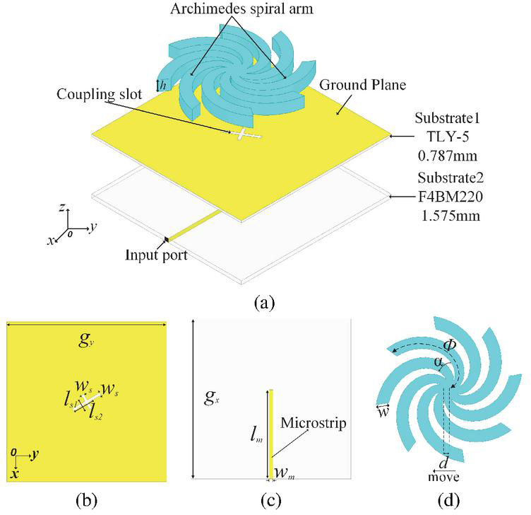
Figure 1 Geometries and dimensions of (a) the proposed ASIDA, (b) top view of substrate1, (c) bottom view of substrate2 and (d) top view.
Table 1 Key parameters of ASIDA (unit: mm)
| 250 | 250 | 28 | 50 | 4.9 | 20 |
| 142 | 7 | 20.5 | 0.787 | 1.575 | 8 |
As shown in Fig. 1, represents the starting radius of the spiral, a denotes the growth rate of the spiral, and is the angle on the spiral arm. The equation for the inner edge of a single Archimedean dielectric arm is given by:
| (1) |
The outer edge curve equation of the single Archimedean dielectric arm is given by:
| (2) |
where the angle of Archimedes’ spiral is , the spiral growth rate a is 34.5 mm/rad, the arm width is w, and its height is h. The inner and outer radius of the single arm are defined by:
| (3) |
The other spiral arms are generated by rotating a single arm in sequence at the angular spacing , thus forming eight arms in total. Detailed dimensions of the ASIDA are listed in Table 1. Based on the geometrical parameters of the dielectric spiral arms and the unequal-length cross-slot feed, the proposed antenna is ultimately designed to operate over the frequency range of 1.5–2.4 GHz.
2.2 Design flow of the proposed ASIDA
The design process of the proposed antenna is shown in Fig. 2. Figure 3 gives the surface current distributions on the ground plane without the radiator at 1.8 GHz for four characteristic phase angles (0∘, 90∘, 180∘, 270∘), where the current vectors exhibit periodic rotational behavior with orthogonal directional switching at T/4 intervals, confirming the CP generation mechanism. The corresponding simulated and AR results are shown in Fig. 4. The three antenna types all exhibit wide impedance bandwidths, consistent with the wideband characteristics of spiral antennas; however, their 3 dB AR bandwidths differ significantly. As the number of arms increases, both the impedance and AR bandwidths widen. Specifically, the AR bandwidths range from 7% to 39.1%.
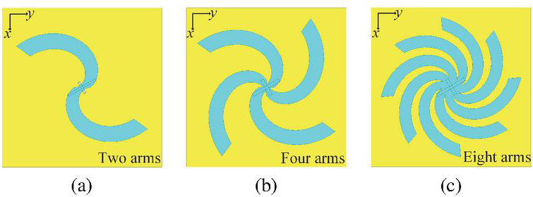
Figure 2 Design process of the proposed antenna: (a) Type I, (b) Type II, and (c) Type III.
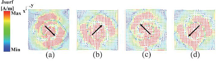
Figure 3 Surface current distribution in the ground plane at 1.8 GHz (a) 0∘, (b) 90∘, (c) 180∘, (d) 270∘.
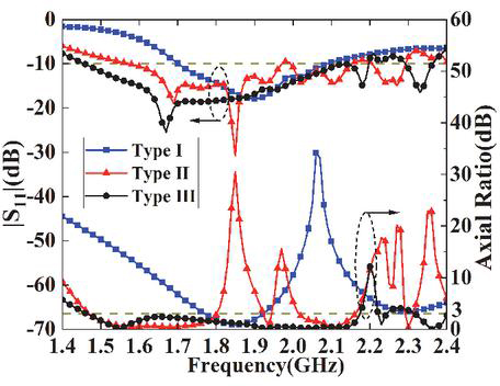
Figure 4 Simulated and AR results of the three types.
Figure 5 (a) presents a comparison of the realized gains for the three antenna types. Compared to Type I and Type II, the Type III antenna demonstrates more stable gain and higher values across the entire operating frequency band. The simulated realized right-hand circular polarization (RHCP) and left-hand circular polarization (LHCP) gains of Type III is shown in Fig. 5 (b). It is observed that Type III achieves the peak RHCP gain of 12.3 dBic at 2.04 GHz.
To further explain the AR change trend, the electric field distributions of the three antenna types at 1.8 and 2.1 GHz are shown in Fig. 6. All three types exhibit gradual outward leakage of electromagnetic waves along the spiral arms. In other words, the electric fields radiate the CP waves as they propagate. However, compared with Types I and II, the surface electric field of Type III exhibits a good right-hand rotation performance along the spiral arm, resulting in efficient RHCP wave radiation. Since these eight arms are involved in radiation, Type III achieves a higher gain. The radiation patterns of Type III at the sideband frequency points of 1.5 and 2.05 GHz are given in Fig. 7. Type III has good radiation performance and low back lobe within the frequency band.
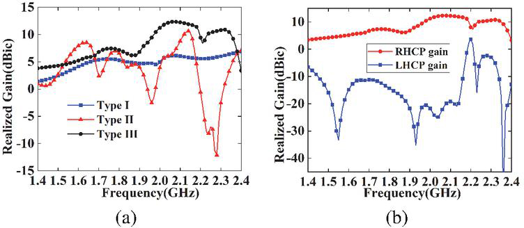
Figure 5 (a) Simulated realized gains of Type I (2-arms), Type II (4-arms), and Type III (8-arms) antennas. (b) Simulated RHCP and LHCP realized gains of Type III antenna.
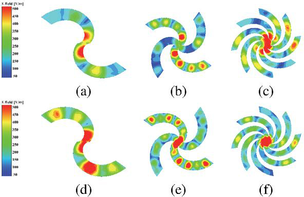
Figure 6 Simulated electric field distributions at 1.8 GHz for (a) Type I, (b) Type II, (c) Type III, and at 2.1 GHz for (d) Type I, (e) Type II, (f) Type III.
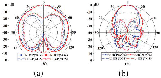
Figure 7 Normalized radiation patterns of the Type III at (a) 1.5 and (b) 2.05 GHz.
2.3 Parameter optimization of the proposed ASIDA
For Type III, the parameter optimization of the proposed ASIDA is performed in this part. Figure 8 illustrates the effects of the spiral growth rate a and the height h on the AR and . When the spiral growth rate a increases, both AR and impedance bandwidth decrease. As the height h increases, the impedance bandwidth decreases, while the AR initially shifts toward lower frequencies. At mm, the low-frequency AR performance remains unchanged, but significant degradation occurs in the high-frequency AR characteristics. To achieve optimal impedance matching and AR performance simultaneously, the values of mm/rad and mm are selected as the compromise.
Figure 9 presents the parametric analysis of the dielectric arm width w and cross-slot rotation angle . As illustrated in Fig. 9 (a), w significantly influences the frequency-dependent characteristics of the AR bandwidth, where excessive width values degrade the high-frequency radiation performance. Figure 9 (b) experimentally validates that governs the orthogonal phase difference, consistent with the theoretical analysis in section IIA. The optimized design configuration with mm and demonstrates an optimal balance between impedance matching and AR bandwidth performance.
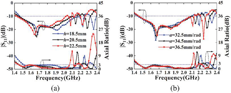
Figure 8 Parametric effects of (a) spiral growth rate a and (b) dielectric height h on simulated and AR.
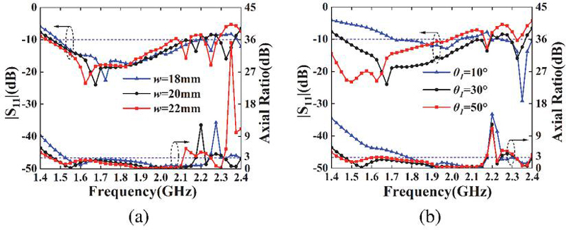
Figure 9 Simulated results of and AR with the different (a) spiral arm width w and (b) unequal-length cross-slot angle .
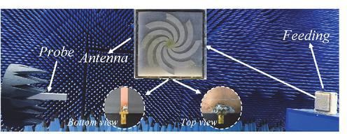
Figure 10 Photographs of the proposed antenna and testing anechoic chamber.
3 EXPERIMENTAL RESULTS AND DISCUSSION
In this section, the proposed ASIDA is fabricated, measured, and its simulated and measured results are compared and analyzed. To ensure fabrication accuracy, a modular strategy is adopted by dividing the overall spiral structure into eight individual spiral arms and a central octagonal support, which are fabricated separately and assembled using a foam jig for precise alignment and fixation.
Photographs of the proposed ASIDA and testing anechoic chamber are shown in Fig. 10. The simulated and measured and efficiency results are presented in Fig. 11. Due to no conductor loss and low-loss materials Al2O3 (), the ASIDA maintains a radiation efficiency exceeding 87% at the operation band. The simulated impedance bandwidth is 40.4% (1.46–2.20 GHz), while the measured bandwidth is 40.8% (1.54–2.33 GHz).
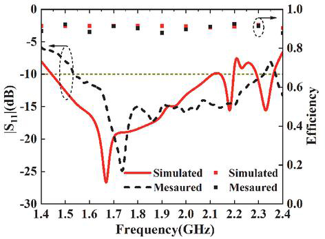
Figure 11 Comparisons for and efficiency of the proposed ASIDA.
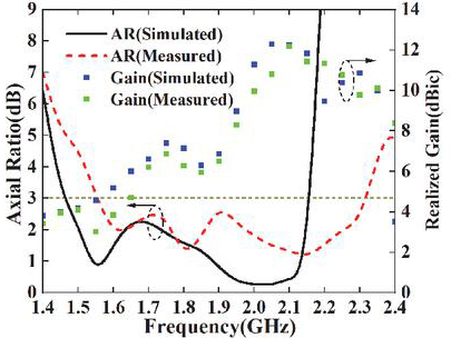
Figure 12 Comparisons for AR and realized gain of the proposed ASIDA.
Table 2 Comparison of the proposed antenna and the previous wideband DRAs
| Ref. | 10 dB | 3-dB | Overlapping | Peak Gain | Size () | Dielectric | Radiating |
| Imp-BW | AR.BW | BW | (dBic or dBi) | Type | |||
| [10] | 34.3%/36.6% | 30.4%/32.9% | 30.4%/32.9% | 6.18/6.58 | NA | 9.9 | DRA |
| [12] | 41.2% | 26.7% | 26.7% | 4.75 | 10.2 | DRA | |
| [17] | 36% | 26% | 26% | 8.7 | 36 | DRA | |
| [18] | 29% | 24.9% | 24.9% | 9 | 32 | DW | |
| [19] | 22.2% | 9.7% | 9.7% | 25 | 10 | DW | |
| This Work | 40.8% | 39.8% | 39.8% | 12.2 | 9.8 | IDW | |
| Imp-BW is the frequency range over which the reflection coefficient remains below 10 dB. Overlapping BW is the frequency range where impedance bandwidth and AR bandwidth overlap. AR BW is the frequency range over which the axial ratio (AR) remains below 3 dB. is the wavelength of an electromagnetic wave propagating inside a dielectric material with relative permittivity . NA: Not Available; DW: dielectric waveguide; IDW: Image-dielectric waveguide. |
|||||||
Figure 12 compares the simulated and measured results of AR and realized gain. The simulated and measured AR bandwidths are 39.1% (1.46–2.17 GHz) and 39.8% (1.55–2.32 GHz), respectively. ASIDA achieves a maximum measured realized gain of 12.2 dBic. Figure 13 shows the simulated and measured normalized radiation patterns of the ASIDA. The differences between simulated and measured results may arise from discrepancies in ASIDA fabrication, assembly, and dielectric constant tolerances.
Finally, comparison results of the proposed ASIDA and other wideband CP dielectric antennas are summarized in Table 2. The proposed ASIDA exhibits a wider impedance and AR bandwidth than those reported in [18, 19] and a higher gain than that in [18]. The image-dielectric waveguide line is implemented to achieve a lower profile compared to [18, 19]. With its advantages in wide impedance and AR bandwidth, low profile, and high gain, the proposed ASIDA shows strong potential as a candidate for future wireless communication and navigation applications.
In addition, several other designs listed in Table 2 are also considered for comparison. The antennas in [10, 12, 17] employ dual-feed structures, reconfigurable circuits, or multilayered geometries to achieve wideband CP operations. These designs have the structure complexity or larger size. In contrast, the proposed single-fed ASIDA achieves wideband CP with a structurally simple and compact design, highlighting its practical advantages in integration and implementation.
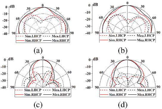
Figure 13 Simulated and measured radiation patterns of the ASIDA: (a) xoz plane at 1.6 GHz, (b) yoz plane at 1.6 GHz, (c) xoz plane at 2.15 GHz, and (d) yoz plane at 2.15 GHz.
4 CONCLUSION
In this paper, a wideband CP ASIDA with the eight arms is proposed. The image-dielectric waveguide line is adopted to achieve a low profile, and the eight Archimedean-spiral image-dielectric arms with the unequal-length cross-slot feed achieves wider AR bandwidth of 39.8% in a compact size. The measured results show that the proposed ASIDA has a wide impedance bandwidth of 40.8% (1.54–2.33 GHz) and a wide AR bandwidth of 39.8% (1.55–2.32 GHz), with a maximum realized gain of 12.2 dBic. The proposed ASIDA design demonstrates good performance in terms of impedance bandwidth, AR bandwidth, and gain, offering valuable insights for the design of wideband CP antennas. The ASIDA exhibits potential applications in wireless communication systems and satellite navigation systems.
REFERENCES
[1] C. Zhu, G. Xu, A. Ren, W. Wang, Z. Huang, and X. Wu, “A compact dual-band dual-circularly polarized SIW cavity-backed antenna array for millimeter-wave applications,” IEEE Antennas and Wireless Propag. Lett., vol. 21, no. 8, pp. 1572–1576, Aug. 2022.
[2] Q. Wu, J. Hirokawa, J. Yin, C. Yu, H. Wang, and W. Hong, “Millimeter wave planar broadband circularly polarized antenna array using stacked curl elements,” IEEE Trans. Antennas Propag., vol. 65, no. 12, pp. 7052–7062, Dec. 2017.
[3] H. Xue, L. Wu, Z.-L. Xiao, and T.-Y. Hu, “A low-profile broadband circularly polarized patch antenna with wide axial-ratio beamwidth,” IEEE Antennas Wireless Propag. Lett., vol. 22, no. 9, pp. 2115–2119, Sep. 2023.
[4] Y. Cheng and Y. Dong, “Wideband circularly polarized split patch antenna loaded with suspended rods,” IEEE Antennas Wireless Propag. Lett., vol. 20, no. 2, pp. 229–233, Feb. 2021.
[5] W. Tan, X. Shan, and Z. Shen, “Ultrawideband circularly polarized antenna with shared semicircular patches,” IEEE Trans. Antennas Propag., vol. 69, no. 6, pp. 3555–3559, June 2021.
[6] P. Mallick, M. Ameen, R. Chowdhury, A. K. Ray, and R. K. Chaudhary, “Wideband circularly polarized cavity-backed dielectric resonator antenna with low RCS for aerial vehicle communications,” IEEE Antennas Wireless Propag. Lett., vol. 21, no. 7, pp. 1418-1422, July 2022.
[7] X. Ruan and C. H. Chan, “A circularly polarized differentially fed transmission-line-excited magnetoelectric dipole antenna array for 5G applications,” IEEE Trans. Antennas Propag., vol. 67, no. 3, pp. 2002-2007, Mar. 2019.
[8] Y.-W. Zhong, G.-M. Yang, J.-Y. Mo, and L.-R. Zheng, “Compact circularly polarized Archimedean spiral antenna for ultrawideband communication applications,” IEEE Antennas Wireless Propag. Lett., vol. 16, pp. 129-132, 2017.
[9] S. Ranjit, S. Chakrabarti, and S. K. Parui, “A dual circularly polarized substrate integrated waveguide antenna for X-band application,” in Proc. IEEE Microw., Antennas, Propagat. Conf. (MAPCON), pp 1308-1312, 2022.
[10] B.-J. Liu, J.-H. Qiu, C.-H. Wang, W. Li, and G.-Q. Li, “Polarization-reconfigurable cylindrical dielectric resonator antenna excited by dual probe with tunable feed network,” IEEE Access, vol. 7, pp. 60111-60119, 2019.
[11] J.-E. Zhang, Q. Zhang, W. Kong, W.-W. Yang, and J.-X. Chen, “Compact and low-profile linear-/circular-polarization dielectric resonator antennas with extended bandwidths,” IEEE Open J. Antennas Propag., vol. 3, pp. 391–397, 2022.
[12] C. Tong, H. I. Kremer, N. Yang, and K. W. Leung, “Compact wideband circularly polarized dielectric resonator antenna with dielectric vias,” IEEE Antennas Wireless Propag. Lett., vol. 21, no. 6, pp. 1100–1104, June 2022.
[13] A. A. Abdulmajid, Y. Khalil, and S. Khamas, “Higher-order-mode circularly polarized two-layer rectangular dielectric resonator antenna,” IEEE Antennas Wireless Propag. Lett., vol. 17, no. 6, pp. 1114–1117, June 2018.
[14] X. C. Wang, L. Sun, X. L. Lu, S. Liang, and W.-Z. Lu, “Single-feed dual-band circularly polarized dielectric resonator antenna for CNSS applications,” IEEE Trans. Antennas Propag., vol. 65, no. 8, pp. 4283–4287, Aug. 2017.
[15] M.-D. Yang, Y.-M. Pan, Y.-X. Sun, and K.-W. Leung, “Wideband circularly polarized substrate-integrated embedded dielectric resonator antenna for millimeter-wave applications,” IEEE Trans. Antennas Propag., vol. 68, no. 2, pp. 1145–1150, Feb. 2020.
[16] T.-W. Chen, W.-W. Yang, Y.-H. Ke, and J.-X. Chen, “A circularly polarized hybrid dielectric resonator antenna with wide bandwidth and compact size,” IEEE Antennas Wireless Propag. Lett., vol. 22, no. 3, pp. 591–595, Mar. 2023.
[17] W.-J. Sun, W.-W. Yang, L. Guo, W. Qin, and J.-X. Chen, “A circularly polarized dielectric resonator antenna and its reconfigurable design,” IEEE Antennas Wireless Propag. Lett., vol. 19, pp. 1088–1092, July 2020.
[18] S. Wang, F. Fan, Y. Xu, Z.-C. Guo, W. Zheng, Y.-T. Liu, and Y. Li, “3-D printed zirconia ceramic Archimedean spiral antenna: Theory and performance in comparison with its metal counterpart,” IEEE Antennas Wireless Propag. Lett., vol. 21, no. 6, pp. 1173–1177, June 2022.
[19] T. Lira-Valdés, E. Rajo-Iglesias, and F. Pizarro, “3-D-printed spiral leaky wave antenna with circular polarization,” IEEE Open J. Antennas Propag., vol. 4, pp. 427–433, 2023.
[20] C.-Y. Huang, J.-Y. Wu, and K.-L. Wong, “Cross-slot-coupled microstrip antenna and dielectric resonator antenna for circular polarization,” IEEE Trans. Antennas Propag., vol. 47, no. 4, pp. 605–609, Apr. 1999.
BIOGRAPHIES

Dong Chen was born in 2001. He received his B.S. degree from Chongqing Jiaotong University, Chongqing, China, in 2023. He is currently pursuing his M.S. degree, in Anhui University. His current research interests include dielectric resonator antenna and millimeter-wave antenna.

Guanghui Xu was born in 1986. He received the B.E. degree from Anhui Jianzhu University, Hefei, China, in 2009, the M.E. degree from Shenzhen University, Shenzhen, China, in 2012, and the Ph.D. degree from the Department of Electronic Engineering, Shanghai Jiao Tong University, Shanghai, China, in 2019. His research interests include millimeter-wave (mm-wave) antenna and reconfigurable antennas.

Yanbin Luo received the B.S. degree from the China University of Mining and Technology, Xuzhou, China, in 2015. He is currently pursuing the Ph.D. degree with Beijing University of Posts and Telecommunications, Beijing. His research interests include graphene/GaAs nanowire photodetectors, graphene reconfigurable antennas, wideband antennas, and miniaturized antennas.

Wei Wang received the Ph.D. degree in navigation, guidance, and control from Harbin Engineering University (HEU), Harbin, China, in 2005. He was a Post-Doctoral Research Associate at Harbin Institute of Technology, Harbin, from July 2006 to April 2009. His current research interests include location, mapping, and image processing.

Dawei Ding received the B.E. degree from Jiangsu University, Zhenjiang, China, in 2009, and the Ph.D. degree from the University of Science and Technology of China, Hefei, in 2015. He is currently an Associate Professor with the School of Electronic Engineering, Anhui University, Hefei. His research interests include antenna theory and design, multiobjective optimization methods, and microwave circuit design.

Luyu Zhao was born in Xi’an, China, in 1984. He received the B.Eng. degree from Xidian University, Xi’an, in 2007, and the Ph.D. degree from The Chinese University of Hong Kong, Hong Kong, in 2014. His current research interests include design and application of multiple antenna systems for next generation mobile communication systems, innovative passive RF and microwave components and systems, millimeter wave and terahertz antenna array, and meta-material-based or inspired antenna arrays.

Yingsong Li received the B.S. degree in electrical and information engineering and the M.S. degree in electromagnetic field and microwave technology from Harbin Engineering University (HEU), Harbin, China, in 2006 and 2011, respectively, and the Ph.D. degree from the Kochi University of Technology (KUT), Kochi, Japan, and Harbin Engineering University (HEU) in 2014. His research interests include remote sensing, underwater communications, signal processing, adaptive filters, metasurface designs, and microwave antennas.

Zhixiang Huang was born in 1979. He received the B.S. and Ph.D. degrees from Anhui University, Hefei, China, in 2002 and 2007. His research interests include theoretical and computational research in electromagnetics and imaging, focusing on multiphysics and interdisciplinary research, and fundamental and applied aspects in metamaterials and active metamaterials.

Xianliang Wu was born in Bozhou, Anhui, China, in 1955. He is a Second-Level Professor, a Ph.D. Supervisor, and the Academic and Technological Leader of Anhui. He has been engaged in teaching and scientific research in electromagnetic field theory, mobile communications, electromagnetic scattering theory of complex targets, and electromagnetic field numerical calculation. His research interests include theoretical and computational research in electromagnetics and imaging, focusing on multiphysics and interdisciplinary research, and fundamental and applied aspects in metamaterials and active metamaterials.
ACES JOURNAL, Vol. 40, No. 10, 1030–1036
DOI: 10.13052/2025.ACES.J.401008
© 2025 River Publishers