Effect of Corrosion on Electromagnetic Shielding Effectiveness of Enclosures with Gasketed Seams
Xin He, Gang Zhang, Yin Shi, Lixin Wang, Zhongliang Du, and Zhitian Wang
1Department of Robotics and Advanced Manufacture
Harbin Institute of Technology, Shenzhen 518000, China
21B953013@stu.hit.edu.cn, wlx@hit.edu.cn
2Department of Electrical Engineering and Automation
Harbin Institute of Technology, Harbin 150000, China
Zhang_hit@hit.edu.cn, 1425978482@qq.com, 23S106100@stu.hit.edu.cn, wzt20120811@gmail.com
Submitted On: May 18, 2025; Accepted On: July 29, 2025
ABSTRACT
Gasketed seams are a primary pathway for electromagnetic leakage in enclosures, and corrosion at these seams can significantly worsen the leakage. Therefore, this work investigates the degradation of shielding effectiveness (SE) in enclosures with gasketed seams when exposed to corrosive environments. Since corrosion products typically exhibit low electrical conductivity, a simulation analysis is first conducted to examine how variations in seam conductivity affect the SE of the enclosure. Subsequently, experiments are conducted on the enclosure with gasketed seams to evaluate changes in its SE after being exposed to a corrosive environment. Experimental results show that enclosures with gasketed seams exhibit a significant decline in SE when exposed to corrosive environments. For improving the SE of enclosures and mitigating the adverse effects of corrosion, installing electrically conductive rubber gaskets is a more effective solution than using finger stock gaskets.
Index Terms: Corrosion, electromagnetic interference gasket, enclosure, shielding effectiveness.
I. INTRODUCTION
Installing shielded enclosures is a common and effective solution for preventing electromagnetic leakage and interference in electronic devices. Ideally, an enclosure should consist of a continuous metal casing. However, seams are inevitable during manufacturing, which can lead to electromagnetic leakage and a reduction in shielding effectiveness (SE) [1]. Installing electromagnetic interference (EMI) gaskets or applying techniques such as riveting and welding can improve the electrical continuity of the enclosure, thereby enhancing its SE [2]. The enclosure is vulnerable to electrochemical corrosion at the seams when exposed to corrosive environments [3]. This degradation can compromise the electrical continuity at the seams, thus diminishing the enclosure’s immunity to conducted and radiated disturbances. Therefore, it is essential to investigate the impact of corrosion on the SE of enclosures with gasketed seams.
The EMI gaskets typically offer good conductivity and sealing capability, and they are installed in the seams to minimize electromagnetic leakage. Various EMI gaskets are available to meet different practical requirements, among which conductive rubber and finger stock gaskets are the most commonly used. Conductive rubber and finger stock gaskets are widely used in the electromagnetic compatibility (EMC) design of enclosures. In [4], it is demonstrated that conductive silicone rubber gaskets filled with silver-plated glass particles exhibit high stability under severe vibration and intense simulated electromagnetic pulse (EMP) conditions, recommending their application in critical military applications. In [5] and [6], a combination of modified Bethe’s small aperture theory and filtering theory is employed to investigate the impact of corrosion on the performance of finger stock gaskets. Although these studies examined the characteristics of two different types of EMI gaskets and their effectiveness in enhancing the SE of enclosures, they did not compare the performance of the two gasket types under identical operating conditions, such as a corrosive environment.
Enclosures are highly susceptible to electrochemical corrosion when exposed to atmospheric, marine, and similar environments for extended periods. Galvanized steel is commonly used as a material for shielding enclosures. In marine atmospheric environments, factors such as sodium chloride (NaCl) solution concentration and exposure duration significantly influence the corrosion behavior of galvanized steel [7]. When exposed to electrolyte solutions, enclosures undergo galvanic and electrolytic corrosion. These corrosion processes occur at the joint interfaces of the enclosure, thereby compromising electrical continuity and reducing SE [8]. Open circuit potential and electrochemical impedance measurements can be used to predict the corrosion characteristics of EMI gaskets [9].
To evaluate the electromagnetic shielding performance of the enclosure, the most straightforward method is to measure the SE. The SE testing methods are outlined in [10], which are commonly used for enclosures and shielding materials [11–14]. However, measuring SE is often complex and costly. Study [15] demonstrates a one-to-one correspondence between the SE of the enclosure and the transfer impedance of the gasket. Based on this conclusion, related studies investigate the SE of enclosures by measuring the transfer impedance of gaskets [16–19]. Although measuring the gasket’s transfer impedance simplifies the testing process, it does not enable accurate determination of the enclosure’s SE and fails to directly reflect its electromagnetic shielding capability.
In summary, understanding the degradation mechanism of enclosures in corrosive environments and enhancing the reliability of enclosure design are key topics in EMC and environmental reliability. However, research relevant to this aspect is insufficient. This work primarily focuses on a comparative analysis of three types of seam structures: filling with conductive rubber gaskets, finger stock gaskets, and metal-metal contact (without EMI gaskets). This work examines the effects of corrosion on seam structures and their impact on SE through both simulation and experimental studies. Continuous corrosion tests are conducted on various seam configurations, and the SE of enclosures is measured and compared across different exposure durations. This work also examines the impact of various gasket materials on SE under corrosive conditions, offering valuable guidance for engineers in selecting gaskets suitable for such environments.
The rest of this work is organized as follows. Section II analyzes the mechanisms by which corrosion affects the SE of enclosures. Section III presents simulation studies that examine the impact of seam conductivity on the SE of enclosures. In section IV, experimental measurements are carried out to determine the SE variations in enclosures with three types of gasketed seams after exposure to corrosive environments. Finally, section V concludes this work.
II. THEORETICAL BACKGROUND
A. Corrosion mechanisms of seam structures
As categorized in [1], corrosion can be classified into eight types based on their characteristics and underlying mechanisms: uniform corrosion, galvanic corrosion, crevice corrosion, pitting corrosion, intergranular corrosion, selective corrosion, erosion corrosion, and stress corrosion. For the gasketed seam investigated in this work, the presence of joint seams promotes the accumulation of corrosive solutions, making it highly vulnerable to crevice corrosion. Additionally, if the gasket and enclosure are made of different materials, galvanic corrosion is likely to occur once a conductive solution enters the seam. Among various corrosion types, crevice corrosion and galvanic corrosion are the most prominent mechanisms affecting gasketed seams. Therefore, this study mainly focuses on these two types of corrosion.
1. Crevice corrosion
Enclosures assembled using riveting, welding, or bolted connections typically contain seams at their joints. Corrosive media can accumulate in these seams and react with the metal surfaces, resulting in crevice corrosion. This type of localized corrosion can occur in all metals and alloys, particularly on surfaces of metals that tend to form passive films. Metals susceptible to crevice corrosion develop irregular pits of varying depths within crevices covered by corrosion products, leading to the formation of enclosed galvanic cells. The self-catalyzing nature of these cells is the primary factor accelerating the progression of crevice corrosion.
To mitigate the risks of crevice corrosion, enclosure materials should preferably be selected from metals and alloys with a reduced tendency for self-passivation, such as stainless steels with higher molybdenum (Mo), chromium (Cr), or nickel (Ni) content. Additionally, the design should minimize the presence of crevices and dead-end areas. When seamless construction is impractical, filling crevices with solid materials can help maintain electrical continuity across the enclosure surface.
2. Galvanic corrosion
Seam structures filled with EMI gaskets are often prone to galvanic corrosion. This type of corrosion occurs when dissimilar metals with different electrochemical potentials come into contact in the presence of an electrolyte. The metal with the lower corrosion potential serves as the anode, losing electrons through oxidation reactions and undergoing accelerated local corrosion. In contrast, the metal with the higher corrosion potential functions as the cathode, gaining electrons through reduction reactions and thus being protected from corrosion. Although galvanic corrosion improves the corrosion resistance of the cathodic material, it also speeds up the corrosion of the anodic material. As a result, the overall corrosion rate of the joint structure rises, reducing its corrosion resistance.
Installing finger stock gaskets in enclosures raises the risk of galvanic corrosion at contact joints between dissimilar metals in the seams, potentially accelerating metal degradation. In conductive rubber gaskets, most metal particles are encapsulated within the rubber matrix, thereby limiting their direct contact with the enclosure. Consequently, when exposed to a corrosive environment, galvanic corrosion is confined to the few metal particles present on the gasket surface that are in contact with the enclosure. Therefore, compared to finger stock gaskets, conductive rubber gaskets pose a lower risk of galvanic corrosion at the gasketed seams.
EMI gaskets are typically made from conductive materials with relatively high electrochemical potentials, while enclosures are often constructed from highly malleable metals with lower potentials. This potential difference drives galvanic corrosion at the interface of contact. To mitigate galvanic corrosion in enclosures with gasketed seams, it is important to minimize the electrochemical potential difference between contacting materials.
B. Shielding effectiveness
SE is primarily used to describe the electromagnetic shielding effect of a shield. For electric fields, SE is expressed as:
| (1) |
where and are the electric field strengths at the same position before and after shielding. For magnetic fields, SE is expressed as:
| (2) |
where and are magnetic field strengths at the same position before and after shielding. In the far-field region, holds.
A shield with seams can be considered a combined wall comprising seams and metal panel regions. According to the research in [21], the overall SE of the shield can be expressed as:
| (3) |
in which represents the SE of the ith region, is the width of the ith region, W signifies the total width of the N regions, meaning the width of the shield. Equation (3) describes the relationship between the overall SE of the shield and the SE contributions from its sub-regions. According to (3), regions that provide sufficiently high SE contribute minimally to the overall SE because they show little electromagnetic leakage. In contrast, regions with low SE dominate the overall shielding performance, since they are the primary sources of electromagnetic leakage. For a shield that includes structures like gaskets and apertures, it can be divided into regular regions and weaker regions containing these features. Because of the lower SE in these weak regions, they mainly determine the overall SE of the shield. This shows that improving the SE of weak regions, such as gasketed seams and apertures, can significantly enhance the shield’s overall performance.
When incident EM waves encounter a shield, they undergo reflection, transmission, and absorption processes, as illustrated in Fig. 1. The SE of the shield is affected by these processes. The SE in decibels of the shield can be expressed as [22]:
| (4) |
where R, A, and M represent reflection loss, absorption loss, and multiple reflection factor.
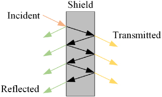
Figure 1: Propagation behavior of EM waves upon encountering a shield.
Assuming the incident EM waves originate sufficiently far from the shield, they can be approximated as uniform plane waves. For a shield with a thickness of , the following equations hold [23]:
| (5) |
is the wave impedance in vacuum, is the skin depth, and is the intrinsic impedance of shield. and can be obtained through:
| (6) |
in which f is the frequency of the EM waves, denotes the angular frequency, is the conductivity of the shielding material, H/m represents the permeability of free space, F/m is the permittivity of free space, and are the relative permittivity and relative permeability of the shielding material.
Since the value of is very small and the shield typically has high electrical conductivity, it follows that . Then, can be written as:
| (7) |
In (7), the value of is relatively small. Thus, for a shield with high electrical conductivity, holds. Finally, the SE of the shield can be approximately expressed as:
| (8) |
and it can be deduced from (3) to (8) that the SE of the shield is positively correlated with .
III. SIMULATION AND RESULTS
As mentioned in section II, the seam structures of a shield are prone to severe corrosion when exposed to a corrosive environment. This corrosion degrades the electrical continuity at the seams. Specifically, the corrosion products (mainly oxides and metal salts with low conductivity) accumulate on the contact surfaces, reducing the conductivity of the seam area. For a seam structure, its SE is positively correlated with its conductivity, as can be derived from (8). Therefore, once corrosion occurs, the SE of the seam structure decreases. In contrast, the metal panel regions outside the seams are typically thick enough that corrosion affects only the surface layer. As a result, these panels maintain good electrical continuity and can still provide high SE. Consequently, the seams represent the weakest point of the shield and the overall SE of a shield with seams is heavily depends on the SE of the seam structures, as indicated by (3).
In summary, the conductivity of the seam structure has a significant impact on the overall SE of the shield. To demonstrate this supposition, this section investigates the effect of seam conductivity on the shield’s overall SE through simulation.
A. Simulation setup
A 3D simulation model of the shielding enclosure is constructed in Ansys HFSS, based on the physical structure shown in Fig. 2 (a) and clarified in Fig. 2 (b). The enclosure is made of iron and has a cubic shape with a side length of 310 mm and a wall thickness of 5.6 mm. The test plate is a square iron plate measuring 380 mm per side. A square test window (200 mm per side) is cut into the test plate and an iron cover plate with a side length of 260 mm is mounted over the window. The gasket is installed at the joint of the cover plate and the test plate, with a total length of 480 mm.
As described in [21], the actual gasketed seam can be modeled as a uniform and isotropic structure. By adjusting the conductivity of the model, the gasketed seam can be made equivalent to the actual one. Therefore, in this section, the complex actual gasketed seam is simplified into a uniform and isotropic model. As mentioned earlier, corrosion degrades the electrical continuity of the actual gasketed seam. In the simulation, this effect is represented by reducing the conductivity of the gasket model. However, it should be noted that, since the impact of corrosion on gasket conductivity cannot be accurately quantified, the simulations in this work can only provide a qualitative analysis of its effect on SE.
In the simulation model, the seam width between the two contacting cover plates is set to 2 mm. The initial conductivity of the seam material is set to 1000 S/m and is gradually reduced to 100 S/m, 10 S/m, and 1 S/m to simulate the progressive material degradation caused by corrosion. A tetrahedral mesh with adaptive refinement is used to accurately capture critical geometric and electromagnetic features. A plane wave with an amplitude of 1 V/m is incident normally on the test panel. An electric field probe is positioned at the geometric center of the enclosure to measure the internal electric field strength. Based on these measurements, the SE of the enclosure is calculated. In the HFSS simulation, the boundary condition is set to ‘Radiation,’ and adaptive meshing is employed. The solver’s maximum delta energy is specified as 0.01 to ensure convergence. A discrete frequency sweep is conducted over the range of 0.5-1.5 GHz with a step size of 0.01 GHz. The simulation results are shown in Fig. 3.
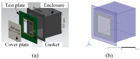
Figure 2: Enclosure model: (a) physical structure of the enclosure and (b) corresponding simulation model.
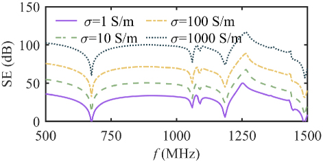
Figure 3: SE simulation results for different seam conductivities.
B. Analysis of simulation results
As shown in Fig. 3, the conductivity of the seam material significantly impacts the SE of the enclosure. In actual corrosive environments, both the conductivity and the geometric characteristics of the contact surfaces undergo considerable changes due to corrosion. These changes substantially degrade the electrical continuity at the seams, resulting in increased electromagnetic leakage and a corresponding reduction in SE.
Conductivity of the gasket model is set to 1 S/m, and distributions of the electric field, magnetic field, and surface current of the enclosure at 1 GHz are illustrated in Figs. 4, 5, and 6.
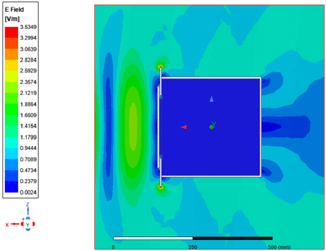
Figure 4: Electric field distribution in the XZ-plane within the solution region.
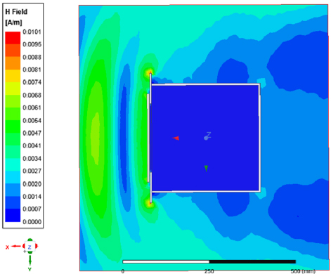
Figure 5: Magnetic field distribution in the XY-plane within the solution region.
As shown in Figs. 4 and 5, the enclosure provides effective shielding against both electric and magnetic fields. Aside from the edges of the cover, the electric field and magnetic field intensity peaks mainly at the seam regions, indicating that these seams serve as the primary pathways for electromagnetic leakage into the interior of the enclosure. The surface current distribution on the enclosure is illustrated in Fig. 6. It can be seen that the surface directly exposed to the incident wave shows higher surface current density. As these surface currents cross the seam with decreased electrical continuity, a voltage drop is created at the seam. This voltage drop acts as a secondary electromagnetic source, re-emitting EM waves into the interior of the enclosure. Consequently, the SE of the enclosure decreases.
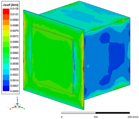
Figure 6: Surface current density of the enclosure.
Simulation and analysis confirm that the seams of the enclosure are a primary factor contributing to degradation of SE. Corrosion-induced degradation at the seams reduces their electrical continuity which, in turn, increases their susceptibility to electromagnetic leakage. Consequently, the seams become more effective pathways for electromagnetic waves to penetrate the enclosure, resulting in a substantial decline in overall shielding performance.
IV. EXPERIMENTAL AND RESULTS
A. Corrosion degradation experiment
To conduct the experiments, a steel shielding enclosure, with the structure and dimensions shown in Fig. 2 (a), is manufactured according to SAE ARP1173 standard [20]. The test seam refers to the interface formed by the connection of the two square cover plates. In the experiments, the test seam configurations are classified into three types: (1) installation of a conductive rubber gasket (Fig. 7 (a)), (2) installation of a finger stock gasket (Fig. 7 (b)) and (3) metal-to-metal overlap without any gasket.
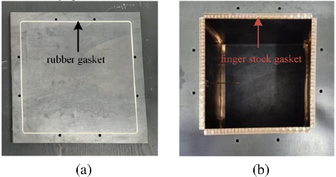
Figure 7: Plates with EMI gaskets installed: (a) conductive rubber gasket and (b) finger stock gasket.
The gasket and two cover plates are assembled into the experimental sample and fastened using bolts. A torque wrench is utilized to ensure a uniform tightening force across all bolts. Since the experimental sample will later be assembled with the enclosure for SE testing, the contact area between the larger cover and the enclosure is covered with Teflon tape to prevent corrosion. The experimental samples are then placed in an acid salt spray test chamber for corrosion degradation testing, as shown in Fig. 8. The experimental setup follows the acetic acid salt spray test specified in the ISO 9227 standard. The test is conducted at a temperature of 35∘C using a 5% (by mass) NaCl solution. The pH of the solution is adjusted to 3.0 by adding glacial acetic acid. Each test cycle lasted 16 hours. After each cycle, the samples are removed, rinsed, dried, and measured for SE before being returned to the test chamber for the next cycle. In this work, each sample underwent five experimental cycles, resulting in a total test duration of 80 hours.
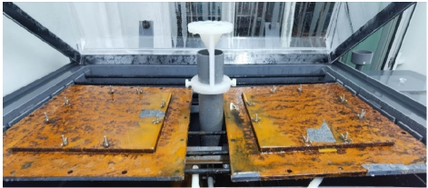
Figure 8: Samples undergoing corrosion testing in the acetic acid salt spray chamber.
After the corrosion test, the appearance of the experimental samples is shown in Fig. 9. Severe corrosion is observed at the seams, accompanied by the accumulation of corrosion products. Based on visual inspection among the three samples, the one with the finger stock gasket exhibited the most severe corrosion, while the one with the conductive rubber gasket showed the least corrosion. This result may be attributed to the conductive rubber gasket providing better sealing, which reduces the accumulation of corrosive solution in the gasketed seam and thereby delays corrosion in that area. In contrast, the installation of a finger stock gasket introduces numerous micro gaps within the seam, allowing corrosive liquid to accumulate and accelerate corrosion in the region.
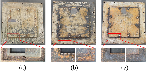
Figure 9: Experimental samples after corrosion degradation testing: (a) conductive rubber gasket, (b) finger stock gasket, and (c) no gasket (metal-to-metal contact).
The surfaces of each gasket material before and after corrosion are examined with a scanning electron microscope (SEM) to reveal the microstructural changes at contact surfaces. The SEM observation results are shown in Fig. 10, captured at a magnification of 500. As shown in Fig. 10, after 80 hours of corrosion, the surface of the conductive rubber remains mostly intact, whereas significant corrosion deposits are observed on the surfaces of the finger stock and iron. These deposits, primarily composed of metal oxides and metal salts, have low electrical conductivity and contribute to the loss of electrical continuity. The transfer impedance of the gasket material, both before and after corrosion, is measured according to the SAE ARP-1705C standard, and the results are presented in Fig. 11. Results show that the transfer impedance of the conductive rubber gasket did not increase significantly after corrosion, whereas the transfer impedance of the finger stock gasket and the iron increased substantially. Since SE is inversely related to transfer impedance, it can be concluded that the samples with finger stock gaskets and those without gaskets will experience noticeable decreases in SE.
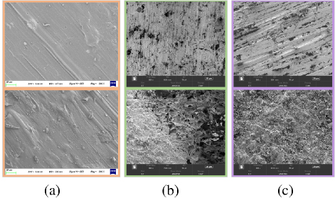
Figure 10: SEM images of gasket material surfaces before and after corrosion: (a) conductive rubber, (b) finger stock, and (c) iron.
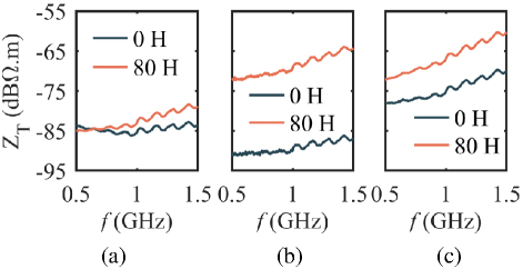
Figure 11: Transfer impedance of gasket material before and after corrosion: (a) conductive rubber, (b) finger stock, and (c) iron.
The results shown in Figs. 9–11 indicate that when corrosion occurs at gasketed seams, corrosion products tend to accumulate on the contact surface. These deposits, mainly consisting of metal oxides and metal salts, have low electrical conductivity. As a result, surface conductivity at the contact interface decreases, transfer impedance of the gasketed seam increases, and electrical continuity is weakened. When surface currents induced by incident electromagnetic waves flow across the gasketed seam, the increased transfer impedance causes a notable voltage drop. This voltage drop acts as a secondary radiation source, introducing electromagnetic energy into the enclosure’s interior. As a consequence, electromagnetic leakage rises, which can lead to a reduction in SE.
B. SE test of the enclosure
The samples shown in Fig. 9 are assembled with the box body to form a complete shielding enclosure. The SE test is then conducted in accordance with the standard specified in [10]. The SE test setup is shown in Fig. 12. The test system consists of an R&S® ZVL3 2-port vector network analyzer (VNA), a power amplifier (PA), a double-ridged horn antenna, a half-wave dipole antenna, and connecting cables. In this work, SE is tested in the frequency range of 500 MHz to 1.5 GHz.
In Fig. 12, the excitation signal generated by Port 1 of the VNA is amplified by the PA and transmitted to the double-ridged horn antenna, which radiates EM waves toward the cover plate of the enclosure. Inside the enclosure, a half-wave dipole antenna serves as the receiving antenna. It captures the EM waves that penetrate the enclosure and delivers the received signal to Port 2 of the VNA. The SE of the enclosure is then calculated based on the measured scattering parameter S21. Specifically, the measurement result obtained without the enclosure is recorded as S21,B, and the result obtained after the enclosure is installed is recorded as S21,T. SE of the enclosure, expressed in decibels (dB), is then calculated using:
| (9) |
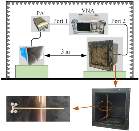
Figure 12: SE test setup.
C. Experimental results and analysis
Following the SE testing procedure, the samples with the three different seam configurations undergo SE measurements. The SE test results of the enclosure with conductive rubber gasketed seams are shown in Fig. 13. It can be observed that SE fluctuates only slightly throughout the entire test period. This result indicates that the conductive rubber gasket is not significantly affected by corrosion, demonstrating that the gasketed seam, where the conductive rubber gasket is installed, exhibits strong resistance to corrosive degradation.
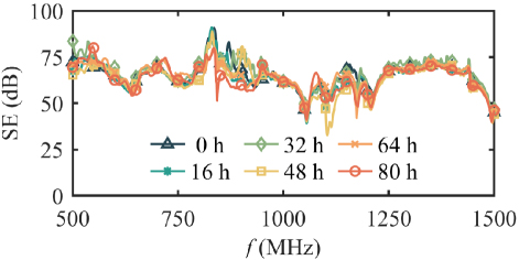
Figure 13: SE enclosure with conductive rubber gasketed seams.
SE test results of the enclosure with finger stock gasketed seams are shown in Fig. 14. It is evident that SE progressively declines with longer corrosion durations. After 80 hours, SE decrease exceeds 20 dB, highlighting that the finger stock gasket fails to offer adequate corrosion protection, resulting in significant deterioration at the seams. A major factor is the presence of multiple gaps in the finger stock gasket, which lacks the sealing and water resistance characteristics that conductive rubber gaskets have. Consequently, corrosive solution accumulates within the gasketed seam, accelerating the corrosion process. The resulting corrosion byproducts, which are poor conductors, hinder the electrical continuity of the gasketed seam and exacerbate EM leakage, ultimately diminishing the overall SE.
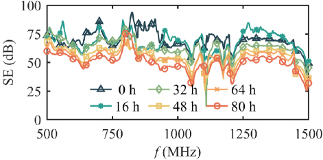
Figure 14: SE of the enclosure with finger stock gasketed seams.
SE test results of the enclosure with metal-metal contact structure at different degradation durations are shown in Fig. 15. These results are similar to those observed with finger stock gasketed seams, showing a decrease in SE with increasing corrosion time. However, the reduction in SE is less pronounced. This result can be attributed to the fact that the two contacting plates are made of the same metal, which eliminates the potential difference required for galvanic corrosion. Only crevice corrosion occurs in the metal-metal contact structure. Consequently, the degradation of the metal-to-metal contact structure is less severe than that observed with finger stock gaskets.
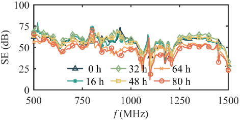
Figure 15: SE of the enclosure with metal-metal contact structure.
Since the conductivity of the gasketed seam in the simulation model differs from that in the actual enclosure, the magnitude of the simulated and measured SE values is not consistent. Compared to the smooth simulation curve shown in Fig. 3, the measured SE curve exhibits fluctuations. This is mainly because the leakage signal level detected by the antenna inside the enclosure is very low, making the measurements vulnerable to instrument background noise. Additionally, the simulation model simplifies the structure by omitting the fastening bolts present in the real enclosure, leading to differences in resonant frequencies between simulation and measurement. Nonetheless, the overall trend of change in both simulation and measurement remains consistent.
SE of the three gasketed seam configurations in their initial uncorroded state is compared and shown in Fig. 16. It can be seen that the sample without any gasket has noticeably lower SE, while the samples with conductive rubber and finger stock gaskets show significantly higher SE with similar performance. This supports the idea that installing EMI gaskets improves electrical continuity at the seams, thereby enhancing the overall electromagnetic shielding performance of the enclosure.
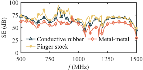
Figure 16: Comparison of the initial SE for the three seam types.
Table 1: Average SE (dB) of three gasketed seams
| Sample | 0 h | 16 h | 32 h | 48 h | 64 h | 80 h |
| Conductive Rubber | 65.1 | 64.1 | 66.5 | 62.8 | 64.0 | 63.4 |
| Finger Stock | 69.5 | 68.1 | 62.8 | 56.1 | 54.1 | 49.7 |
| Metal-Metal | 55.7 | 56.8 | 57.1 | 55.9 | 49.1 | 47.5 |
This work calculated the average SE of samples with a gasketed seam at various stages of corrosion, as summarized in Table 1. The results in Table 1 indicate that among the three tested seam configurations, the seam with the conductive rubber gasket exhibited the least susceptibility to corrosion, while the seam with the finger stock gasket was the most affected. The superior performance of conductive rubber is attributed to its excellent deformability, which allows it to create a tight seal with the enclosure at the seam. This close contact offers some water-blocking ability, reducing the accumulation of corrosive solution on the contact surface. As a result, corrosion progresses more slowly, and the deterioration of SE remains minimal. In contrast, gasketed seams using a finger stock gasket (or those without any gasket) tend to have many small gaps where corrosive solution can accumulate, leading to crevice corrosion and a significant decrease in SE. Additionally, material mismatch between the finger stock gasket and the enclosure can cause galvanic corrosion at the contact surface, further speeding up degradation. Consequently, the sample with the finger stock gasket shows the most notable SE degradation.
To improve the durability of enclosures exposed to corrosive environments, it is essential to design seam structures with water-resistant features that prevent the accumulation of corrosive solutions at contact interfaces. When choosing gasket materials, conductive rubber is preferred due to its superior sealing and corrosion resistance. If finger stock gaskets need to be used, they should be made from the same material as the enclosure or from materials with similar corrosion potentials to reduce galvanic corrosion. These design strategies can greatly enhance the corrosion resistance of the gasketed seam and slow the loss of SE over time.
V. CONCLUSION
This work investigated the degradation of electromagnetic shielding effectiveness (SE) of EMC gaskets caused by corrosion, using an integrated approach that combines experimental corrosion testing, SE measurements, and full-wave electromagnetic simulations in HFSS. Experimental results show that when exposed to a corrosive environment, the contact surface between the enclosure and the electromagnetic interference (EMI) gasket experiences corrosion. Low-conductivity corrosion products accumulate at the interface, increasing transfer impedance across the gasketed seam and decreasing electrical continuity. These changes lead to greater electromagnetic leakage and a corresponding reduction in SE.
The main contributions of this work are as follows: (a) Unlike most studies that evaluate the shielding performance of degraded EMI gaskets in isolation, this work installs the EMI gaskets on an enclosure before subjecting them to corrosion and measuring the SE. This approach better reflects real-world applications and the degradation behavior of EMI-gasketed seams. (b) While existing studies primarily rely on experimental measurements, this work combines both experimental testing and full-wave electromagnetic simulations conducted in HFSS. Shielding degradation is modeled by adjusting the conductivity of the gasket in the simulation model. Once a relationship between measurable physical quantities (such as transfer impedance) and simulated gasket conductivity is established, SE degradation can be accurately predicted. (c) By comparing the corrosion-induced degradation characteristics of different EMI gasket types, this study offers practical recommendations for material selection and seam design in enclosures exposed to corrosive environments. These insights can help mitigate corrosion effects and enhance shielding reliability in real-world applications.
Future work will focus on developing efficient and accurate electromagnetic simulation methods to model EMI gasket degradation caused by corrosion.
REFERENCES
[1] G. J. Gooch and J. K. Daher, Electromagnetic Shielding and Corrosion Protection for Aerospace Vehicles. Berlin: Springer, 2007.
[2] B. Wilmot, “EMI gaskets and their correct application,” in 1992 Regional Symposium on Electromagnetic Compatibility, Tel-Aviv, Israel, pp. 4.2.3/1-4.2.3/2, 1992.
[3] S. K. Das, J. Nuebel, and B. Zand, “An investigation on the sources of shielding degradation for gaskets with zinc coated steel enclosures,” in IEEE 1997, EMC, Austin Style. IEEE 1997 International Symposium on Electromagnetic Compatibility. Symposium Record, Austin, TX, USA, pp. 66-71, 1997.
[4] J. F. Walther, “Electrical stability during vibration and electromagnetic pulse survivability of silver-plated glass bead filled EMI shielding gaskets,” in National Symposium on Electromagnetic Compatibility, Denver, CO, USA, pp. 40-45, 1989.
[5] D. Pouhè and G. Mönich, “Assessment of shielding effectiveness of gaskets by means of the modified Bethe’s coupling theory,” IEEE Transactions on Electromagnetic Compatibility, vol. 50, no. 2, pp. 305-315, May 2008.
[6] D. Pouhè and P. Tcheg, “Study on corrosion-induced shielding-degradation of EMI gaskets,” IEEE Transactions on Electromagnetic Compatibility, vol. 58, no. 4, pp. 1052-1059, Aug. 2016.
[7] X. Yan, Y. Cong, G. Wang, and Z. Zhang, “Effects of various accelerated corrosion conditions on corrosion behavior of galvanized steel in marine atmospheric environment,” in 2022 IEEE Sustainable Power and Energy Conference (iSPEC), Perth, Australia, pp. 1-5, 2022.
[8] J. Xie, M. G. Pecht, S. K. Das, J. Nuebel, and B. Zand, “Corrosion of a zinc-coated steel enclosure at the contact interfaces of gasket joints,” IEEE Transactions on Components and Packaging Technologies, vol. 23, no. 1, pp. 136-142, Mar. 2000.
[9] A. R. Pawlowych, R. J. Thibeau, and M. R. Lambert, “Galvanically compatible elastomeric gasketing material for EMI shielding applications,” in 2004 International Symposium on Electromagnetic Compatibility (IEEE Cat. No.04CH37559), Silicon Valley, CA, USA, vol. 3, pp. 841-845, 2004.
[10] IEEE Standard Method for Measuring the Effectiveness of Electromagnetic Shielding Enclosures, IEEE Std 299-2006, Feb. 2007.
[11] Z. Yan, F. Qin, J. Cai, S. Zhong, and J. Lin, “Shielding performance of materials under the excitation of high-intensity transient electromagnetic pulse,” IEEE Access, vol. 9, pp. 49697-49704, 2021.
[12] Z. Yan, F. Qin, J. Cai, S. Zhong, and J. Lin, “Study on the characterization of shielding effectiveness of materials under wide band electromagnetic pulse,” in 2020 IEEE MTT-S International Conference on Numerical Electromagnetic and Multiphysics Modeling and Optimization (NEMO), Hangzhou, China, pp. 1-3, 2020.
[13] M. Pavlík, A. Gladyr, and J. Zbojovský, “Comparison of measured and simulated data of shielding effectiveness, reflection and absorption of electromagnetic field,” in 2020 IEEE Problems of Automated Electrodrive. Theory and Practice (PAEP), Kremenchuk, Ukraine, pp. 1-4, 2020.
[14] P. Lessner and D. Inman, “Quantitative measurement of the degradation of EMI shielding and mating flange materials after environmental exposure,” in 1993 International Symposium on Electromagnetic Compatibility, Dallas, TX, USA, pp. 207-213, 1993.
[15] J. P. Quine and A. J. Pesta, “Shielding effectiveness of an enclosure employing gasketed seams-relation between SE and gasket transfer impedance,” in Proceedings of International Symposium on Electromagnetic Compatibility, Atlanta, GA, USA, pp. 392-395, 1995.
[16] H. W. Denny and K. R. Shouse, “EMI shielding of conductive gaskets in corrosive environments,” in IEEE International Symposium on Electromagnetic Compatibility, Washington, DC, USA, pp. 20-24, 1990.
[17] D. Pissoort, J. Catrysse, T. Claeys, F. Vanhee, B. Boesman, and C. Brull, “Towards a stripline setup to characterise the effects of corrosion and ageing on the shielding effectiveness of EMI gaskets,” in 2015 IEEE International Symposium on Electromagnetic Compatibility (EMC), Dresden, Germany, pp. 7-12, 2015.
[18] A. N. Faught, “An introduction to shield joint evaluation using EMI gasket transfer impedance data,” in 1982 IEEE International Symposium on Electromagnetic Compatibility, Santa Clara, CA, USA, pp. 1-7, 1982.
[19] R. J. Mohr, “Evaluation technique for EMI seams,” in 1987 IEEE International Symposium on Electromagnetic Compatibility, Atlanta, GA, USA, pp. 1-4, 1987.
[20] Test procedure to measure the RF shielding characteristics of EMI gaskets, SAE-ARP 1173-2004, 2004.
[21] G. Zhang, X. He, L. Wang, D. Yang, Y. Shi, H. Zhang, and A. Duffy, “Equivalent simulation approach for the shielding effectiveness of enclosures with gasketed seams,” IEEE Transactions on Electromagnetic Compatibility, pp. 1-10, 2025.
[22] S. Celozzi, R. Araneo, P. Burghignoli, and G. Lovat, Electromagnetic Shielding: Theory and Applications. Hoboken, NJ: John Wiley & Sons, 2023.
[23] S. Kovar, J. Valouch, and H. Urbancokova, “Calculation of shielding effectiveness of materials for security devices,” MATEC Web of Conferences, vol. 125, p. 02036, 2017.
BIOGRAPHIES

Xin He was born in Wenshan, China, in 1996. He received the B.S. and M.Sc. degrees in electrical engineering from the Harbin Institute of Technology (HIT), Harbin, China, in 2019 and 2021, respectively. He is currently working toward the Ph.D. degree in electrical engineering with HIT, Shenzhen. His research interests include cable fault detection and location, and electromagnetic compatibility analysis.

Gang Zhang was born in Tai’an, China, in 1984. He received the B.S. degree in electrical engineering from the China University of Petroleum, Dongying, China, in 2007, and the M.S. and Ph.D. degrees in electrical engineering from the Harbin Institute of Technology (HIT), Harbin, in 2009 and 2014, respectively. He is currently a professor in electrical engineering with HIT, and a visiting professor with the University of L’Aquila, L’Aquila, Italy. His research interests include electrical contact theory, uncertainty analysis of electromagnetic compatibility, and the validation of CEM.

Yin Shi was born in Harbin, China, in 1999. He received the B.S. and M.Sc. degrees in electrical engineering from the Harbin Institute of Technology (HIT), Harbin, China, in 2022 and 2025, respectively. His research interests include electrical contact theory, shielding effectiveness, and finite element simulation.

Lixin Wang received the B.S. degree in electrical engineering from Nankai University, Tianjin, China, in 1988, and the M.S. and Ph.D. degrees in electrical engineering from the Harbin Institute of Technology (HIT), Harbin, in 1991 and 1999, respectively. He is currently a professor of power electronics and electric drives with HIT, Shenzhen. He conducts research with Faults Online Monitoring and Diagnosis Laboratory, HIT, on a wide variety of topics including electromagnetic compatibility at the electronic system level, aircraft electromechanical fault diagnosis expert system, and prediction and health management (PHM) of Li-ion battery.

Zhongliang Du was born in Mudanjiang, China, in 2000. He received the B.S. degree in electrical engineering from Shandong University, Jinan, China, in 2023. He is currently pursuing the M.Sc. degree in electrical engineering with Harbin Institute of Technology (HIT). His research interests include electromagnetic compatibility technology of power electronic devices.

Zhitian Wang was born in Changchun, China, in 2002. He received the B.S. degree in electrical engineering from Harbin Institute of Technology (HIT), Harbin, China, in 2023, where he is currently pursuing the M.Sc. degree. His research interests include modeling of conducted interference, design of active EMI filter, and finite element simulation.
ACES JOURNAL, Vol. 40, No. 8, 767–777
doi: 10.13052/2024.ACES.J.400809
© 2025 River Publishers