Analysis of an Oil-Spray Cooling System for an Induction Switched Reluctance Machine Using Computational Fluid Dynamics
Narges Ghandi, Hadi Saghafi∗, and Mohammadali Abbasian
Department of Electrical Engineering
Institute of Artificial Intelligence and Social and
Advanced Technologies, Isf.C., Islamic Azad University, Isfahan, Iran
narges.ghandi@iau.ac.ir, h.saghafi@iau.ac.ir, m.a.abbasian@iau.ac.ir
*Corresponding Author
Submitted On: May 18, 2025; Accepted On: July 7, 2025
ABSTRACT
The growing interest in electric vehicles has spurred the development of high-performance electric machines. The effective cooling of windings in electric machines is essential as they are the primary site of energy loss. Oil-spray cooling systems have gained popularity due to their ability to reduce temperatures and protect winding insulation. This paper proposes a Computational Fluid Dynamics (CFD) model for the Spray-Cooling Induction Switched Reluctance Machine (ISRM) to enhance the thermal management of electric machines using Ansys Fluent software. The proposed machine demonstrates efficient heat dissipation during transient simulation tests. Oil is applied to both the stator and the rotor during a transient two-phase simulation, enabling effective thermal exchange despite uneven temperature distributions across the components. We first modeled the machine using the finite element method and extracted the losses from ANSYS. This analysis focuses on the energy losses related to the selective oil spray at the end of the rotor. By performing a detailed thermal analysis, we found that increasing the flow rate enhances the Nusselt number, improves heat transfer, and increases the machine losses.
Index Terms: Electric vehicle, Induction Switched Reluctance Machine (ISRM), oil-spray cooling, two-phase thermal management systems.
I. INTRODUCTION
Permanent Magnet Synchronous Motors (PMSMs) and Switched Reluctance Motors (SRMs) are high torque density motors. PMSMs are recognized for their high torque density. In contrast, SRMs are valued for their simple structure, high efficiency, reliability, cost-effectiveness, high fault tolerance, excellent thermal abilities, and suitable torque-speed characteristics [1].
This study builds upon recent advancements in SRM technology, addressing limitations in existing designs. While significant progress has been made in noise reduction techniques using Torque Sharing Function (TSF)-based control [2] and sophisticated modeling approaches [3], there remains a need for robust design optimization methods considering realistic driving cycles. Early work focused on enhancing SRM performance by introducing designs like the Double Stator SRM (DSSRM) in 2010 [4], aimed at mitigating torque ripple and acoustic noise often associated with conventional SRMs. However, the DSSRM design might still face challenges in high-power applications.
Recently, the Induction Switched Reluctance Machine (ISRM) has emerged as a promising alternative, particularly well-suited for demanding industrial and transportation applications [5]. The ISRM utilizes a non-segmented design, with coils placed on both the stator and rotor cores. This configuration, although it introduces rotor copper losses, offers superior efficiency compared to conventional SRMs [6]. The unique design of the ISRM allows for various stator/rotor pole combinations and provides flexibility in optimizing machine performance for specific applications.
The 12/10 ISRM configuration for electric powertrains represents an approach in the Electric Vehicles (EVs) powertrains field [7]. This machine combines the SRM with rotor inductive conductors to improve EV powertrain performance. The rotor conductors act as a magnetic shield, enhancing efficiency by creating short magnetic flux paths. Mohammadi et al. [8] examined an oil-cooled, three-phase ISRM with six stator poles and four rotor poles. A two-dimensional finite element model was used to analyze the machine’s magnetic properties, flux path, torque, and efficiency, followed by an analysis of thermal performance with ANSYS Motor-CAD [8].
However, these rotor conductors also lead to significant copper loss and heat generation. While direct liquid cooling systems, like oil-spray cooling used in the Toyota Prius, can cool the internal parts of the machine, designing an ISRM with reduced rotor copper loss can eliminate the need for cooling systems and enhance the machine’s efficiency. Consequently, it is essential to perform a detailed thermal analysis and optimize the design of the spray cooling system. This subject has not been considered in the literature until now, and it is the main innovation of this paper.
Oil cooling is increasingly recognized as an effective method for thermal management in electric machines, but several aspects require further investigation. Compared to oil-jet cooling, spray cooling offers superior cooling efficiency and more uniform temperature distribution [9, 10]. Research in two-phase thermal management systems has focused on leveraging both liquid and vapor phases to enhance heat transfer. The average velocity of droplets in a spray is used to characterize their speed. Wang et al. [11] used an artificial neural network to analyze the Nusselt number in an EW (End Winding) spray cooling system, addressing uneven spray cooling and its impact on cooling efficiency.
Several studies have investigated specific aspects of oil cooling systems. Zhang et al. [12] details the development of a 3D Lumped Parameter Thermal Network (LPTN) for oil-spray-cooled EWs, while others have explored the effectiveness of spray evaporative cooling in electric motors [21, 22]. These studies often utilize electric traction motor stators with hairpin winding technology and specialized spray nozzles [13]. Depending on the specific application, some cooling systems are better suited for effective thermal management, and Computational Fluid Dynamics (CFD) modeling becomes an essential research tool for guiding and enhancing the design process. For example, Chiu et al. [14] carried out a CFD simulation of a 30 kW SRM to make a comparison between liquid and air-cooling systems.
In the scope of this study, a thermal model dedicated to spray-cooling ISRM has been formulated, evaluated, and adapted for a different ISRM configuration based on the CFD approach. The work begins by illustrating the structure of the ISRM, with a particular focus on the internal arrangement of components and the areas most prone to overheating, such as the stator and rotor. The proposed cooling system relies on the direct application of oil jets, designed to target the most thermally critical surfaces specifically. The three-dimensional model used for simulation is described in detail, including the geometry of the motor, the distribution and orientation of the nozzles, the oil flow rate, pressure, and the fluid’s physical properties.
A spray-cooling three-phase ISRM with 12 stator poles and 10 rotor poles was analyzed, and a 2D finite element model was developed to determine its magnetic properties. In this paper, 24 two-phase spray nozzles were specifically designed, and thermal simulations were performed and utilized for cooling purposes. Six nozzles were allocated for the stator and six for the rotor, arranged radially at the front and rear of the ISRM. Radial rotor spray cooling seems to be the better solution, using Ansys Fluent software. Through simulations conducted under various operating scenarios, the study shows that oil-spray cooling can significantly reduce the internal temperatures of the motor. In particular, a substantial temperature drop is observed in areas with higher loss densities, contributing to more continuous operation and a reduced risk of material degradation. Initially, the 12/10 ISRM setup involving oil-spray cooling was employed to establish and confirm a correlation for the Nusselt number. This article, validated with the Nusselt number equation in [15], fully aligns with the findings of this research and reports similar results.
II. INDUCTION SWITCHED RELUCTANCE MACHINE
ISRM refers to an electric machine with a single stator and rotor, featuring several short-circuited coils mounted on the rotor. These coils are energized by additional coils located within the slots of the stator. The rotor’s coils, which are not powered by any external source, have currents induced within them due to the machine’s operation. The rotor’s windings are arranged to create a short magnetic flux path encircling the coil in the stator that is being excited [7, 16]. This type of electric machine, which combines the advantages of reluctance and induction machines, has specific operating characteristics that make the study of its cooling system an original contribution, especially when compared to the existing literature, which is more focused on permanent magnet or conventional induction machines.
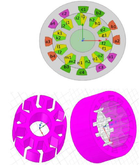
Figure 1: Cross-section of a 12/10 ISRM 2D, 3D.
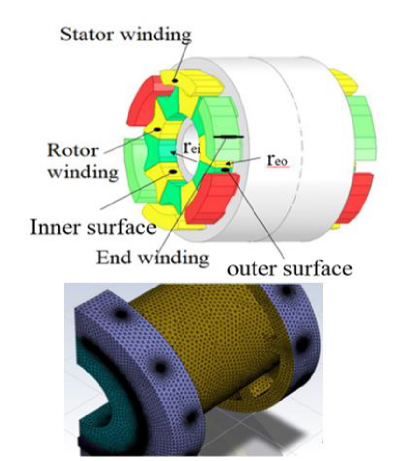
Figure 2: Proposed prototype three-dimensional schematic of 12/10 ISRM simulated with ANSYS and meshed with finite elements.
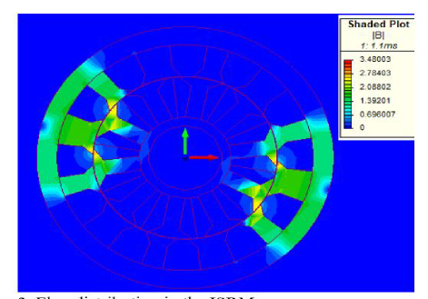
Figure 3: Flux distribution in the ISRM.
The electric machine uses spray cooling for the stator and rotor in this research. Twenty-four spray nozzles are utilized, with six nozzles dedicated to cooling the stator and another six for the rotor. These nozzles are strategically placed at radial positions on the front and rear sections of the ISRM. The research presented involves developing and simulating a thermal model specifically for the spray-cooled 12/10 ISRM. Empirical formulas, derived and simulated within the ISRM framework [15] are central to this effort.
The study validates the thermal model by comparing it with measurement results from electric motors featuring various cooling system designs, also discussed in [15]. Additionally, the formulated Nusselt number equation aligns with the ISRM parameters. The three-dimensional model used for simulation is described in detail, including the geometry of the motor, the distribution and orientation of the nozzles, the oil flow rate, pressure, and the fluid’s physical properties. Two- and three-dimensional representation of the 12/10 ISRM is illustrated in Fig. 1, depicting the key structural features necessary for electromagnetic analysis. Visual representations, including a three-dimensional schematic of its stator and rotor and meshed with finite elements, are depicted in Fig. 2. Further details about the 12/10 ISRM’s specifications can be found in Table 1. Figure 3 shows the magnetic flux distribution in the ISRM, while Fig. 4 illustrates the current density in the ISRM.
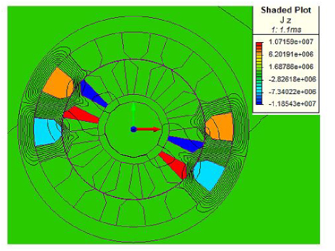
Figure 4: Current density in the ISRM.
Table 1: Specifications of the ISRM
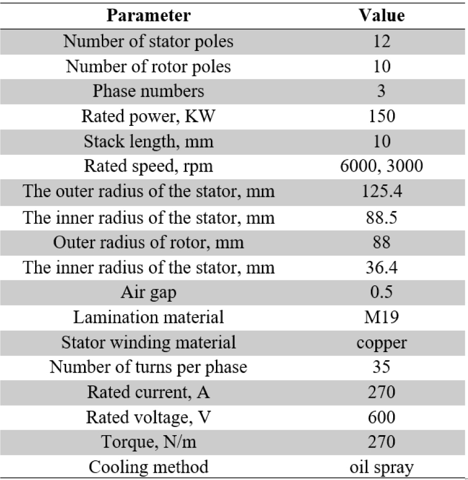
Table 2: Automatic transmission fluid coolant properties
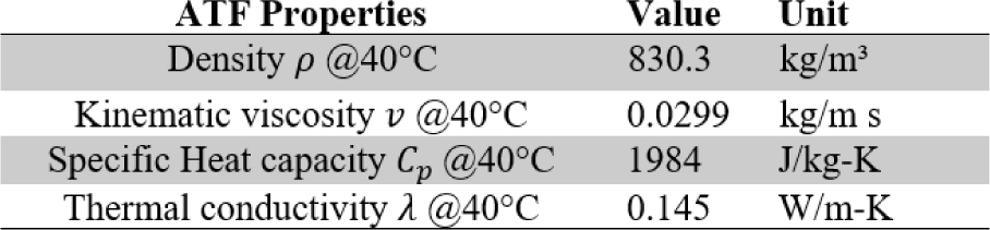
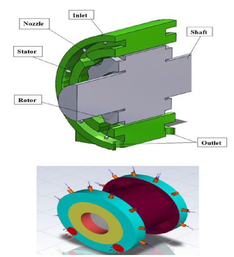
Figure 5: Schematic of the proposed 12/10 ISRM machine with the spray cooling system.
III. SPRAY COOLING SYSTEM
The nozzles are placed in a specific radial position from the stator and the rotors. The housing design of the ISRM device minimizes the contact area between the ISRM suspension and the stator cover, reducing heat transfer through the housing of the simulated device.
A. Simulated spray cooling induction switched reluctance machine
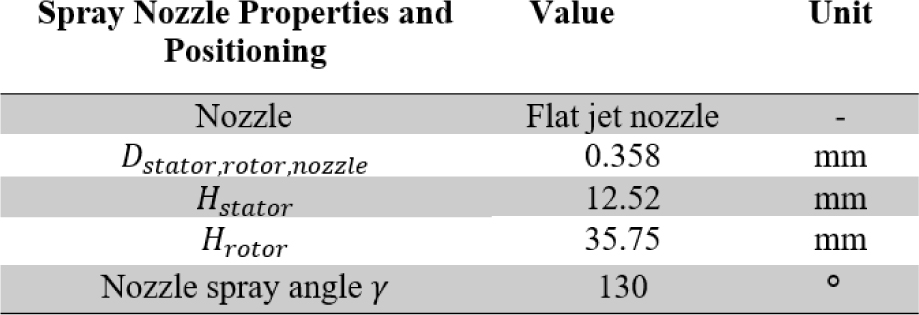
The coolant used in the ISRM is Automatic Transmission Fluid (ATF). Table 2 outlines the liquid’s properties, which are essential for comprehending its behavior in fluid dynamics and thermal processes. The key parameters in Table 2 include fluid density (), kinematic viscosity (v), specific heat capacity (Cp), and thermal conductivity (). These properties are crucial for analyzing fluid movement and heat transfer in systems, such as those using spray nozzles for cooling. The literature documents various nozzle designs explored for numerous spray applications [17]. Flat jet nozzles are used in the ANSYS simulation shown in Fig. 5. The geometry and arrangement of the nozzles are given in Table 3. Table 3 typically includes critical parameters such as the nozzle diameter, angle of spray, and spacing between nozzles, which are essential for ensuring optimal performance in their respective applications. The critical parameters in Table 3 for effective nozzle performance include the spray nozzle type, dimensions (Dstator, Drotor, Dnozzle), and distances from the nozzle to the stator (Hstator) and rotor (Hrotor) surfaces. These factors are essential for precise spray coverage and cooling efficiency.
Table 3: Spray nozzle properties and positioning
B. Fluid circuits
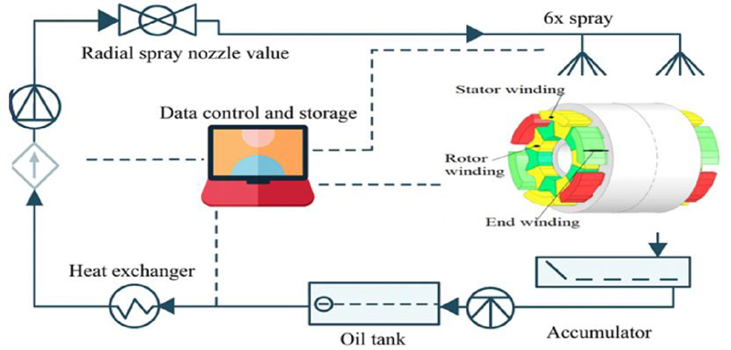
Figure 6: Setting up the proposed cooling fluid system.
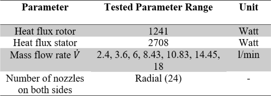
Table 4: Range of parameters altered in the series of measurements
The machine cooling settings of ISRM are in the form of two circuits. The first fluid circuit regulates the cooling water that lowers the temperature of the ATF. The ATF used for cooling the end windings is circulated through a second fluid circuit, which also serves the liquid cooling system for the ISRM.is carried in the liquid circuit for ISRM cooling. A pump transfers the ATF fluid to the injection nozzles to create the fluid pressure required for injection. Two manual valves are proposed to adjust the radial spray of the nozzles. After the ATF fluid is sprayed on the coils, it is collected in the stator coil tank and then transferred to the storage tank from the designed outlet position. Finally, the fluid is directed to the radiator for cooling and enters the injection cycle again. This process is instrumental in lowering the temperature of the windings, thereby enhancing the overall performance of the device, as depicted in Fig. 6.
C. Parameter range of the study area
In this study, multiple parameters listed in Table 4 are systematically modified and simulated to assess their impact on the system’s performance.
IV. HYDRODYNAMIC PARAMETERS OF SPRAYS
In the ISRM, a cooling fluid spray system is utilized. This section investigates two approaches to the simulated heat transfer model. In this study, the average temperatures from each side of the ISRM are employed to calculate the heat transfer coefficients for both model approaches. Local heat transfer behavior and temperature heterogeneities are not investigated further. In this research, a heat transfer model approach should be developed that can be transferred to different dimensions of the machine, and therefore, the complexity of the model needs to be reduced. The heat transfer coefficient is calculated as follows:
| (1) | ||
| (2) |
Stator iron losses can be neglected. At this low frequency, the air gap of the rotor was chosen to be relatively large, and its maximum speed was set to n6000 rpm, so the losses due to air friction can be neglected. Table 2 contains all additional properties of the fluid.
A. Approach 1: Based on Liu et al.
The first model approach simulated test is based on an idea for a model with reduced parameters from Liu et al. [10, 13]:
| (3) | ||
| (4) |
where is the effective volumetric flow rate (see Tables 5 and 7) and is the characteristic length:
| (5) | ||
| (6) |
Due to the different axial distances between the spray nozzle and the EW in DE (Drive End) and NDE (Non-Drive End), two different characteristic lengths in the axial direction are studied, while one characteristic length in the radial direction is investigated.
B. Approach 2: Nusselt number
The alternate method utilizes a single-phase heat transfer paradigm for spray nozzles, defining the Nusselt number with Suter’s mean diameter, the d32. The specified diameter refers to that of a droplet whose ratio of volume to surface area matches the collective ratio for all droplets within the spray sample. Employing the spray’s Reynolds number (see Table 7 for details) [18]:
| (7) | ||
| (8) |
Nusselt number:
| (9) |
Reynolds number:
| (10) |
Prandtl number:
| (11) | ||
| (12) | ||
| (13) | ||
| (14) |
The surface tension of the ATF is denoted as , is sourced from the research conducted by Kemp and Linden [19].
C. Heat transfer surface model
In this study, three end-winding surface area (AEW) models will be used to calculate the effective volumetric flow rate. Both heat transfer models utilize the same three surface modeling methods. Mainly, models of EW are applicable in evaluating cooling system operations and in assessing the efficacy of heat transfer within electric engines and various devices. Utilizing empirical evidence and mathematical formulations, these models determine the effective volumetric flow rate, taking into account the ambient conditions and the specific properties of the substance. For example, EW models can aid in identifying the optimal strategy for dispersing heat and lowering temperatures in oil-cooled electric machines.
The length of EW iswhere Lrad is based on the ideas of trigonometric manipulations for the modeling approach by Liu and colleagues [13] (see Fig. 7):
| (15) | ||
| (16) | ||
| (17) |
where rEW,i is the inner surface radius of the end-winding and rEW,o is the outer surface radius of the end-winding.
Table 5: Experimental Nusselt correlation coefficients for different nozzle arrangements [15]
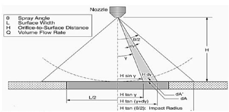
Figure 7: Radial spray arrangement [20].
Consistent with previous heat-transfer research in electrical machinery, the fundamental shape of an end-winding is often reduced to a model resembling half of a circular band [13]. An interesting part of the work concerns the comparison between two distinct approaches to modeling heat transfer. The first is based on empirical correlations derived from previous studies, while the second uses dimensionless parameters such as Nusselt, Reynolds, and Prandtl numbers to describe the forced convection produced by the spray. This comparison helps identify the conditions under which each method is more reliable and representative of the real behavior of the system. Another merit of this paper is the clear connection it establishes between improved cooling and machine performance.
D. Model development
For the analysis of heat transfer behavior, the average chain temperatures from all measured points on each side of the EW are utilized. All empirical and model-based heat transfer coefficients are determined using the same surface model, which varies according to the spray nozzle configuration. The thermal model incorporates all relevant governing equations, including conservation of mass, momentum, and energy, which are explicitly stated in the paper. Boundary conditions were applied using a finite element framework, with Dirichlet and Neumann conditions set according to physical constraints of each domain.
In this paper, the geometry of the model was meshed using the Fluent meshing method in the Fluent software. The type of mesh selected for this simulation is a polyhedral mesh, which is highly suitable for complex models and particularly for simulating fluid flows and physical fields. This type of mesh was chosen due to its specific features, such as high accuracy in simulation and better performance in complex geometries. The number of meshed elements in this model is 256,000, which effectively improves the simulation accuracy in sensitive areas.
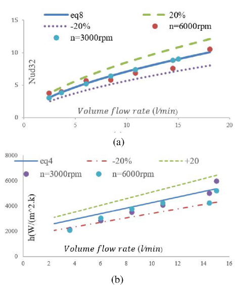
Figure 8: Comparison of (a) Nusselt number and (b) heat transfer rate as a function of coolant flow rate (l/min) of the ISRM stator. Simulated data are plotted against calculated values derived from equations (4) and (8).
The selected solution type is pressure-based and was used in transient mode for precise analysis of fluid dynamics. This simulation was conducted in a two-phase model using the Volume of Fluid (VOF) method, which is suitable for simulating two-phase flows such as liquid-gas. The k-epsilon model was used as the turbulence model to simulate turbulent flows and account for complex flow behaviors. For a more accurate simulation, Cell Zone Conditions were defined separately for the rotor and stator. Additionally, to correctly model the interactions between the rotor and stator, a Mesh Interface was defined between these two sections. This Mesh Interface enables proper communication and data transfer between the moving part (rotor) and the stationary part (stator). Due to the geometric symmetry in the model, the Symmetry feature was used, which helps reduce computational time and increase simulation efficiency.
At the system inlet, the mass flow inlet was used to specify the mass flow rate, accurately defining the inlet flow conditions. The specific simulation settings include a pressure-based solution type, transient simulation mode, a two-phase model using VOF with surface tension, and a k-epsilon turbulence model. Cell zone conditions were defined separately for the rotor and stator, with a mesh interface established between them, and the use of a symmetry feature for geometric symmetry. The mass-flow inlet was employed for the mass flow rate. This combination of models and simulation conditions enables accurate simulation of flows, interactions between the rotor and stator, and analysis of two-phase systems in a dynamic and complex environment.
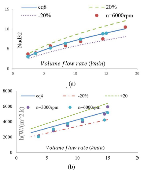
Figure 9: Comparison of (a) Nusselt number and (b) heat transfer rate as a function of coolant flow rate (l/min) of the ISRM rotor. Simulated data are plotted, derived from equation (4), and against calculated values derived from equations (4) and (8).
Regression models were utilized to calibrate the heat transfer coefficients, pinpointing the coefficients and exponents for both methodologies in equations (3) and (7). Identical coefficients (c1-c6) are employed on each side, with the model’s design aimed at pioneering the development of additional ATF spray-cooled traction electric machines. The empirical model treats winding configurations in DE and NDE uniformly, without differentiation. The variance between EW’s two facets is attributed to the disparate lengths of the hairpin wires and their consequent surface dimensions. The data are validated across varying flow rates at 3000 and 6000 rpm, alongside a stator heat transfer measurement of 2708 W, focusing solely on radial spray analysis. The comparison between the heat transfer observed in the experiments in [15] and the simulation using the displacement Nusselt correlation coefficients is depicted in Fig. 8.
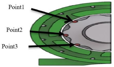
Figure 10: Three-point placement in transient heat transfer.
The measurements taken at different flow rates, specifically at 3000 and 6000 rpm, have verified that the rotor’s heat transfer is 1241 watts. It’s important to note that this study focuses solely on radial spray patterns. Figure 9 clearly shows a noticeable difference in heat transfer between the empirical data and the simulation results, which are calculated using the Nusselt displacement correlation coefficients. This comparison highlights the potential discrepancies and provides a framework for understanding the effectiveness of the radial spray cooling method under different operational conditions. The flow rate is 2-18 liters per minute. The temperature of the ATF fluid ranges from 40 to 150 degrees Celsius. In radial nozzles, the higher the flow rate, the better the cooling performance. The smaller the mean droplet diameter (d32), the more significant the increase in the heat transfer coefficient, and the more extensive the surfacearea (AEW).
V. MODELING AND SIMULATION RESULTS OF TRANSIENT HEAT TRANSFER
In this section, we will analyze the temperature at three distinct points during the transient state for different flow rates, given that the empirical Nusselt formula closely aligns with the simulation results. This analysis will be conducted using ANSYS software, as shown in Fig. 10. This study investigates the temperature changes at several specific points within a thermal system over time. These points are strategically located inside the rotor, where they are continuously influenced by a heat source with a heat flux of 2708 W/m2, which is applied over both the stator and rotor surfaces. In addition to various cooling conditions, the temperature spikes suddenly in localized areas, then, within a fraction of a second, it decreases and stabilizes. Temperature decrease time for different flow rates is shown in Figs. 11 and 12. Temperature reaches its maximum value in 0.2 seconds and then reaches a steady state 0.2 seconds later with the injection of ATF fluid. At different flow rates, the stable temperature is different. Upon motor start-up, a brief initial temperature increase occurs before the cooling system becomes fully effective, which contributes to the sharp thermal response observed in the early stage. This behavior has been validated by comparing our results with experimental data reported in the referenced literature, confirming the accuracy of the thermal model under extreme loading conditions.
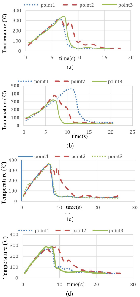
Figure 11: Temperature changes (Celsius) in terms of time (seconds) for different flow rates. (a) Temperature variations at three selected points for a flow rate of 15 liters per minute, (b) temperature variations at three selected points for a flow rate of 12 liters per minute, (c) temperature variations at three selected points for a flow rate of 5 liters per minute, and (d) temperature variations at three selected points for a flow rate of 3 liters perminute.
VI. ENERGY LOSSES FOR ROTORS
The thermal model was developed based on power losses computed using finite element electromagnetic (FEM) simulations in ANSYS Maxwell. These include core losses (hysteresis and eddy currents) and copper losses, which were calculated with spatial resolution and mapped onto the thermal domain in ANSYS. Relevant electromagnetic field maps, such as magnetic flux density and current density distributions, were extracted to visualize regions of high loss concentration.
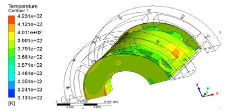
Figure 12: Temperature contour for a flow rate of 3 liters per minute at 3000 rpm.
In addition, mechanical losses arising from fluid resistance and friction along the cooling path have been taken into account. The circulation of the fluid near the stator coils and within the cooling channels results in a pressure drop and increased energy consumption, especially in the rotor region. As the rotor speed increases, these mechanical losses rise accordingly, as shown in Fig. 13. The machine was initially modeled using the finite element method, and all associated losses were extracted through ANSYS simulations.
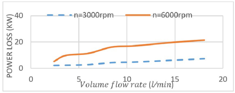
Figure 13: Power loss (KW) relative to flow rate (l/min).
VII. DISCUSSION
Given the operational requirements and engineering considerations, evaluating the feasibility of implementing the proposed system in industrial applications is of particular interest. In the field of electric machine cooling, and particularly in EVs, the oil-spray system presents a promising alternative to conventional liquid- or air-based approaches. It offers not only high thermal efficiency but also a compact structure and reduced maintenance demands. Intelligent pump control strategies can further enhance energy efficiency, while preliminary estimates suggest that the installation and maintenance costs of this system could fall within a competitive range compared to traditional solutions, especially in designs where simplicity and spatial constraints are critical. To estimate the cost of implementing the proposed oil-spray cooling system for electric machines, a simplified analysis was conducted based on a 150-kW motor equipped with 24 nozzles. Key components include a high-capacity pump with intelligent control, a distribution manifold, a reservoir, extended piping, and installation services. Preliminary estimates suggest a total system cost ranging from USD2300-3420, depending on equipment specifications and integration complexity (Table 6).
Cost estimation can be approached using various methods depending on the design phase and required accuracy. Empirical methods leverage data from similar installations; parametric models apply mathematical correlations between system parameters and cost; activity-based costing (ABC) allocates expenses based on actual operational tasks; and bottom-up estimation aggregates costs from individual components. Each method offers distinct advantages across feasibility, detail, and scalability.
Table 6: Summarizing the updated cost estimation for the oil-spray cooling system based on a 150-kW electric machine with 24 nozzles (prices are based on the date the article was submitted)
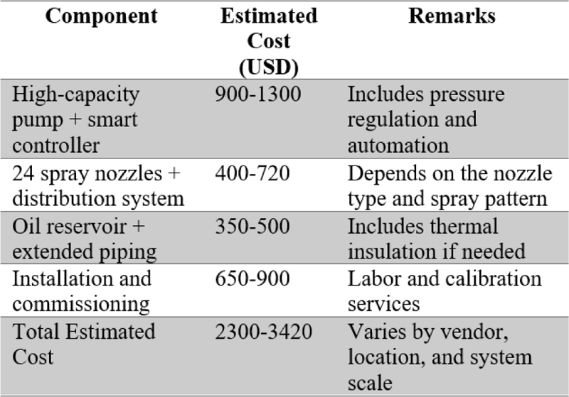
Table 7: Symbols and nomenclature
| Symbol | Nomenclature |
| Area defined along heated surface ( ) | |
| Specific heat capacity (J/kgK) | |
| Coefficients and exponents | |
| Distance (m) | |
| D | Diameter (m) |
| Sauter mean diameter (m) | |
| I | Current (A) |
| Housing losses factor (W/K) | |
| Length (m) | |
| Machine speed ( ) | |
| Nu | Nusselt number |
| Pr | Prandtl number |
| Power losses (W) | |
| Volume flow rate | |
| Heat flow rate (W) | |
| Re | Reynolds number |
| Inlet temperature ( ) | |
| Outlet temperature ( ) | |
| Surface temperature ( ) | |
| Volume flow rate (1/min) | |
| Volumetric flux rate ( ) | |
| Width (m) | |
| Nozzle-to-stator surface distance | |
| Nozzle-to-rotor surface distance | |
| Height of the end-winding | |
| Greek | |
| Heat transfer coefficient ( ) | |
| Spray angle | |
| Temperature difference (K) | |
| Density ( ) | |
| Kinematic viscosity ( ) | |
| Nozzle spray angle ( ∘ ) | |
| Angle (rad) | |
| Subscripts | |
| 0,1… | Counters |
| ax | axial |
| comb | Combined |
| i | inner |
| hydra | Hydraulic |
| 0 | outer |
| Radial |
VIII. FUTURE WORK
Due to the complexity and uncertainties in spray cooling behavior, fuzzy logic, particularly fuzzy similarity analysis, offers a promising direction for future optimization, enabling effective comparison of thermal configurations under nonlinear or uncertain conditions [23].
In this paper, mechanical vibrations and their interaction with thermal performance are of growing importance, particularly in spray-based cooling systems where moving components and nozzles are exposed to dynamic excitation from the motor or installation environment. Modal analysis serves as a fundamental tool for identifying the natural frequencies, mode shapes, and damping ratios of the system, enabling engineers to predict vibrational behavior and avoid destructive phenomena such as resonance.
Modal analysis can be conducted numerically (e.g., via finite element methods) or experimentally (e.g., using impact hammer or shaker tests), and its results form the basis for further dynamic studies such as harmonic response or random vibration analysis. Aligning the system’s natural frequencies away from operational excitation ranges helps prevent fatigue and extends component lifespan.
Moreover, multiphysics modeling, which simultaneously considers thermal, fluidic, and mechanical behavior, offers a more comprehensive understanding of system performance under real-world conditions. For instance, vibrations may influence spray distribution, temperature uniformity, or sensor accuracy. Integrating modal analysis with thermal-fluid simulations thus supports the design of robust, efficient, and vibration-resilient cooling systems.
IX. CONCLUSION
This study introduced an innovative oil-spray cooling system for a 12/10 induction switched reluctance machine (ISRM), showcasing significant advancements in thermal management for Electric Vehicles (EVs). The paper begins by illustrating the structure of the motor, with a particular focus on the internal arrangement of components and the area’s most prone to overheating, such as the stator and rotor. The simulation results indicated that increasing flow rates elevate the Nusselt number, thereby enhancing heat transfer and increasing machine losses. An optimal flow rate of 6 l/min was identified, effectively reducing losses at higher speeds while maintaining coil temperatures below 90∘C. The study also examines the transient thermal response of the motor, simulating the evolution of heat over time and assessing energy losses in the rotor. These data are used to calibrate and validate the proposed models and to identify potential optimization areas. The rotor winding generates heat, which necessitated the design of the spray cooling system.
Our findings indicate that with the current number of nozzles for this machine, there is a heat problem that needs addressing. In comparison to multiphase spray cooling, oil-spray cooling demonstrates a more consistent temperature distribution and superior thermal management capabilities. To facilitate the successful implementation of oil-spray cooling, several practical guidelines are proposed. The configuration of nozzles, including their quantity (24), spray angles (130∘), and placement, significantly influences the uniformity of temperature distribution. While higher flow rates enhance cooling performance, they necessitate greater total flow rates. Additionally, full-cone nozzles have outperformed hollow-cone nozzles regarding heat transfer coefficient (HTC) and overall cooling efficiency. Configurations featuring a larger number of low-flow-rate nozzles yield better cooling efficiency compared to setups with fewer high-flow-rate nozzles.
REFERENCES
[1] O. E. Özçiflikçi, M. Koç, S. Bahçeci, and S. Emiroğlu, “Overview of PMSM control strategies in electric vehicles: A review,” International Journal of Dynamics and Control, vol. 12, pp. 2093-2107, 2024.
[2] A. Chithrabhanu and K. Vasudevan, “Quantification of noise benefits in torque control strategies of SRM drives,” IEEE Transactions on Energy Conversion, vol. 38, no. 1, pp. 585-598, Mar. 2023.
[3] K. Diao, X. Sun, G. Lei, G. Bramerdorfer, Y. Guo, and J. Zhu, “System-level robust design optimization of a switched reluctance motor drive system considering multiple driving cycles,” IEEE Transactions on Energy Conversion, vol. 36, no. 1, pp. 348-357, Mar. 2021.
[4] M. Abbasian, M. Moallem, and B. Fahimi, “Double stator switched reluctance motors: Fundamentals and magnetic force analysis,” IEEE Trans. Energy Convers, vol. 25, no. 3, pp. 589- 597, Dec. 2010.
[5] M. Abbasian, “Induction switched reluctance motor,” U.S. Patent, US20170370296A1, June 30, 2020.
[6] M. Azamian Jazi and M. A. Abbasian, “Preliminary evaluation of induction switched reluctance machine (ISRM) for electric vehicle application,” IEEE Trans. Transport. Electrific., vol. 10, pp. 26693-26701, Dec. 2021.
[7] M. Joodi, M. Abbasian, and M. Delshad, “Introducing a 12/10 Induction Switched Reluctance Machine (ISRM) for electric powertrains,” Applied Computational Electromagnetics Society (ACES) Journal, vol. 39, no. 05, pp. 452-460, May2024.
[8] A. M. Mohammadi, M. Abbasian, M. Delshad, and H. Saghafi, “Electromagnetic and thermal analysis of a 6/4 induction switched reluctance machine for electric vehicle application,” Applied Computational Electromagnetics Society (ACES) Journal, vol. 38, no. 5, pp. 361-370, Sep. 2023.
[9] P. Shams Ghahfarokhi, A. Podgornovs, A. Kallaste, A. J. Marques Cardoso, A. Belahcen, and T. Vaimann, “The oil spray cooling system of automotive traction motors: The state of the art,” IEEE Transactions on Transportation Electrification, vol. 9, no. 1, pp. 428-451, Mar. 2023.
[10] C. Liu, Z. Xu, D. Gerada, F. Zhang, Y. C. Chong, M. Michon, J. Goss, C. Gerada, and H. Zhang, “Experimental investigation of oil jet cooling in electrical machines with hairpin windings,” IEEE Trans. Transport. Electrific., vol. 9, no. 1, pp. 598-608, Mar. 2023.
[11] X. Wang, B. Li, K. Huang, Y. Yan, I. Stone, and S. Worrall, “Experimental investigation on end winding thermal management with oil spray in electric vehicles,” Case Stud. Thermal Eng., vol. 35, p. 102082, July 2022.
[12] F. Zhang, D. Gerada, Z. Xu, C. Liu, H. Zhang, T. Zou, Y. C. Chong, and C. Gerada, “A thermal modeling approach and experimental validation for an oil spray-cooled hairpin winding machine,” IEEE Transactions on Transportation Electrification, vol. 7, no. 4, pp. 2914-2926, Dec. 2021.
[13] C. Liu, Z. Xu, D. Gerada, J. Li, C. Gerada, Y. C. Chong, M. Popescu, J. Goss, D. Staton, and H. Zhang, “Experimental investigation on oil spray cooling with hairpin windings,” IEEE Transactions on Industrial Electronics, vol. 67, no. 9, pp. 7343–7353, Sep. 2020.
[14] C. Chiu, Y. Wang, H. Zhang, and J. Lee, “CFD simulation of a 30-kW switched reluctance motor: Comparison of liquid and air cooling systems,” Case Stud. Therm. Eng., vol. 49, p. 103349, 2023.
[15] P.-O. Gronwald, N. Wiese, M. Henke, and T. A. Kern, “Electric traction motor spray cooling—Empirical model development and experimental validation,” IEEE Transactions on Transportation Electrification, vol. 9, no. 2, pp. 2185-2194, June 2023.
[16] M. Daneshi, M. Abbasian, and M. Delshad, “Comparison of an induction switched reluctance machine with an interior permanent magnet machine using finite element method,” Applied Computational Electromagnetics Society (ACES) Journal, vol. 40, no. 1, pp. 1-7, Jan. 2025.
[17] N. Ashgriz, Handbook of Atomization and Sprays: Theory and Applications. New York, NY: Springer, 2011.
[18] G. Liang and I. Mudawar, “Review of spray cooling—Part 1: Single-phase and nucleate boiling regimes, and critical heat flux,” Int. J. Heat Mass Transf., vol. 115, pp. 1174-1205, Dec. 2017.
[19] S. P. Kemp and J. L. Linden, “Physical and chemical properties of a typical automatic transmission fluid,” Proc. SAE Tech. Paper Ser., pp. 1-14, Oct. 1990.
[20] I. Mudawar and K. A. Estes, “Optimizing and predicting CHF in spray cooling of a square surface,” Journal of Heat Transfer-Transactions of the ASME, vol. 118, pp. 672-679, 1996.
[21] P. H. Mellor, D. Roberts, and D. R. Turner, “Lumped parameter thermal model for electrical machines of TEFC design,” IEE Proceedings B - Electric Power Applications, vol. 138, no. 5, pp. 205-218, 1991.
[22] A. Boglietti and A. Cavagnino, “Analysis of the endwinding cooling effects in TEFC induction motors,” IEEE Transactions on Industry Applications, vol. 43, no. 5, pp. 1214-1222, 2007.
[23] M. Versaci, F. Laganà, L. Manin, and G. Angiulli, “Soft computing and eddy currents to estimate and classify delaminations in biomedical device CFRP plates,” J. Electr. Eng., vol. 76, no. 1, pp. 72-79, Feb. 2025.
BIOGRAPHIES

Narges Ghandi was born in Isfahan, in 1986. She received her B.Sc. degree in Electrical Engineering from Islamic Azad University, Najaf Abad Branch, in 2007, and her M.Sc. degree in the same field from Islamic Azad University, Khomeini Shahr Branch, in 2015. Since 2018, she has been pursuing her Ph.D. in Electrical Engineering at Islamic Azad University, Khorasgan Branch, Isfahan, Iran.

Hadi Saghafi was born in Isfahan, in 1982. He earned his B.Sc. in 2004, M.Sc. in 2007, and Ph.D. in 2014 in power engineering from Isfahan University of Technology. Since 2015, he has been an assistant professor in the Department of Technical Engineering at the Isfahan (Khorasgan) Branch of Islamic Azad University. His research focuses on microgrids, distributed generation, power electronics control, and their applications in power systems.

Mohammadali Abbasian received a bachelor’s degree, M.Sc. degree, and a Ph.D. degree in Electrical Engineering from the Isfahan University of Technology. From 2017 to 2018, he was with the Bundeswehr University, Munich, Germany, as a research scientist. He was an assistant professor at the IAU University, Khorasgan, Isfahan, Iran. His research area is Electrical Machines and Drives.
ACES JOURNAL, Vol. 40, No. 7, 627–638
doi: 10.13052/2024.ACES.J.400707
© 2025 River Publishers