Electromagnetic Exposure to Child Passengers of Positioning Antennas for Autonomous Driving Electric Vehicles
Xuwei Dong, Yufei Ren, and Mai Lu
Key Laboratory of Opto-Electronic Technology and Intelligent Control Ministry of Education
Lanzhou Jiaotong University, Lanzhou 730070, China
dxw007@lzjtu.edu.com, 12232052@stu.lzjtu.edu.com, mai.lu@hotmail.com
Submitted On: March 22, 2025; Accepted On: March 03, 2026
Abstract
With the rapid development of electric vehicles (EVs) and autonomous driving (AD) technologies, the issue of electromagnetic exposure of passengers, especially children, to the electromagnetic radiation generated by the positioning antennas of AD has received increasing attention. In this study, COMSOL Multiphysics is used to construct the models of an EV, a positioning antenna and a child human body, and the levels of electromagnetic exposure of a child passenger to the positioning antenna in AD are calculated. Results indicate that the maximum value of induced electric field in a child’s body is 23 V/m, and the maximum value of the SAR1g of the child’s body is 0.19 W/kg. Additionally, the maximum temperature rise in the child body is 0.55∘C. The electromagnetic exposure levels of the child passenger calculated in this study are all lower than the safety limits defined by international authoritative institutions. Therefore, the electromagnetic radiation levels from the positioning antenna comply with international safety standards. Based on the analysis of this study, no significant health effects on child passengers have been observed. The results of this study can supplement studies on the electromagnetic environment of AD in EVs and can provide guidance for ensuring the travel safety of child passengers.
Index Terms: Autonomous driving, child passenger, electric vehicles, electromagnetic radiation, positioning antenna.
I. INTRODUCTION
In recent years, the global new energy vehicle market has experienced remarkable growth [1]. In contrast to traditional internal combustion engine vehicles, electric vehicles (EVs) produce no exhaust emissions during driving, eliminating the source of harmful gases and contributing to the improvement of the global ecological environment and the protection of public health [2]. As an interdisciplinary field between artificial intelligence and the automotive industry, autonomous driving (AD) EVs have achieved rapid development in recent years [3]. High-precision positioning antennas are critical components for ensuring the safe operation of AD vehicles [4]. The positioning antenna provides centimeter-level or even millimeter-level positioning accuracy for AD vehicles by sending out precise position signals, ensuring that the vehicles can drive safely and stably under complex road conditions.
High-voltage electrical equipment installed in EVs, such as inverters, power cables, and wireless charging systems, generates spatial electromagnetic fields (EMFs) of a certain intensity during operation, exposing passengers to this electromagnetic environment [5, 6, 7]. Meanwhile, with the rapid development of intelligent connected technologies, modern EVs are also integrated with various wireless communication devices, including 4/5G, C-V2X, GPS, Bluetooth, and Wi-Fi antennas. During their operation, these wireless devices also create a high-frequency electromagnetic environment inside the vehicle, rendering the in-vehicle electromagnetic environment more complex. Whilst people are enjoying the convenience of AD vehicles, passengers are inevitably exposed to the electromagnetic environment, and an induction field is formed in the human body [8]. As a special group, children have not yet fully developed physically and may be more sensitive to electromagnetic radiation [9]. Therefore, in the study of electromagnetic exposure to automobile antennas, special attention should be paid to the physical health needs of children to ensure that the electromagnetic exposure level of children meets the safety standards. In view of the physical characteristics and special electromagnetic sensitivity of children, studying the effect of electromagnetic radiation generated by the positioning antenna of AD vehicles on child passengers is crucial and meaningful.
With the vigorous development of a new round of global scientific and technological revolution and industrial transformation, the automotive industry has entered an era of transformation unseen in a century, and EVs have ushered in new development opportunities [10]. Relevant studies have shown that human exposure to the electromagnetic environment generated by the power system of EVs causes certain biological reactions and physiological effects [11, 12]. The safety of human metal medical implants exposed to the wireless power transfer system of EVs was studied, and the results showed that the specific absorption rate (SAR) of human tissues around the metal medical implants would be greater [13]. The induced electric field in different parts of the human body for infants and adults under different driving conditions was analyzed to compare the differences in the induced electric field in the body between children and adults due to physical differences [14]. The electromagnetic exposure of passengers in different positions in the carriage to the radiation of the wireless power transfer system was studied, and the results were all lower than the safety limits specified by International Commission on Non-ionizing Radiation Protection (ICNIRP) [15]. The SAR in adults and children at different locations in the EV under the combined radiation of rod antennas, wire harnesses and DC–DC converters was studied, and the results showed that the amount of electromagnetic radiation suffered by adults and children varied [16] The electromagnetic exposure of adults and children in different postures and positions of the wireless charging system in the EV was evaluated, and the results showed that the induced electric fields of the cardiopulmonary system in lying children and the heart in lying adults exceeded the safety limits specified by ICNIRP [17].
In addition, the explosive development of electronic information technology has filled the human living environment with radiofrequency (RF) EMFs. As early as the mid-20th century, with the emergence of RF applications such as radar technology, scientists began to explore initially the potential effects of radio frequency EMFs on organisms [18]. Although no studies have conclusively shown that RF EMFs would pose adverse effects on human health [19], public concern is increasing, and the study on the radiation characteristics of RF EMFs is also deepening. The effect of the distance and angle between the mobile phone antenna and the human head on the SAR in the human head was studied [20]. Also studied was the influence of vehicle glass antennas placed in different positions in the vehicle on the electromagnetic exposure of passengers [21]. SAR distribution in the human body at different ages and positions for V2V antennas at a frequency of 5.9 GHz was calculated [22, 23]. SAR distributions in a human body for mobile phone users inside a vehicle was evaluated under different scenarios, and the results showed that the SAR value of passengers using mobile phones in the vehicle was 5% higher than that of people using mobile phones in free space [24].
In this paper, the high-precision positioning antenna in AD-EVs is selected as the exposure source. COMSOL Multiphysics software is used to construct the vehicle body model, antenna model and child model. By analyzing the radiation characteristics of the antenna, the distributions of the induced electric field, SAR and temperature in the child passenger’s body are calculated, and the results are compared with the electromagnetic exposure limits stipulated by the international authoritative institutions to evaluate the electromagnetic exposure level in the child’s body. This study aims to provide reference for optimizing positioning antenna design and taking effective protective measures by evaluating the electromagnetic exposure level of child passengers to ensure the safety of children in AD-EVs and promote the rapid development of AD technology.
II. MATERIALS AND METHODS
A. Numerical calculation method
As an interdisciplinary field, bioelectromagnetics reveals the underlying mechanisms of interactions between EMFs and organisms. The Maxwell equations are the foundation of EMF theory and the key to solving EMF problems [25]. In this study, the RF module of COMSOL Multiphysics software based on the finite element method was employed to solve EMF problems by solving the Maxwell equations.
When the positioning antenna of an AD vehicle is operational, it radiates electromagnetic waves into the surrounding space and forms an induction field in the human body when interacting with the human body in the vehicle. SAR, a critical metric for quantifying the amount of electromagnetic radiation energy absorbed by the human body, is defined as [26]:
| (1) |
where is electrical conductivity of the tissue (S/m), is tissue density (kg/m3), and E is electric field strength in biological tissue (V/m).
Human tissues are lossy media. When exposed to an electromagnetic environment, electromagnetic energy is continuously absorbed by human tissues and gradually dissipated in the form of heat [27]. Consequently, the temperature of human tissues rises, resulting in a thermal effect. The Pennes bioheat transfer equation is derived from Maxwell’s equations [28]:
| (2) |
where C is tissue specific heat capacity (J/[kgC]), T is temperature of the tissue (∘C), K is thermal conductivity (W/[mC]), is density of blood (kg/m3), is specific heat capacity of blood (J/[kgC]), is blood perfusion rate (1/s), is temperature of the blood (∘C), is heat generated by metabolism, is external heat source (W/m3). In this paper, the initial temperature of the human body is 36.5∘C, and the external boundary condition of the human body is set to the thermal insulation boundary condition.
B. Dielectric parameters of human tissue
In 1996, on the basis of previous work, Gabriel proposed a four-order Cole–Cole model to calculate the dielectric properties of biological tissues [29]:
| (3) |
where is complex relative dielectric constant, is loss factor, is relative dielectric constant at optical frequency, is relative dielectric constant increment, is central relaxation time (s), is dielectric constant of a vacuum (F/m), is relaxation distribution time , is ionic conductivity (S/m).
During human growth and development, the water content in tissues gradually decreases with age. The water content of biological tissues considerably influences the dielectric properties of tissues [30]. As age increases, the downward trends of the dielectric constant and electrical conductivity of most biological tissues are consistent with the downward trend of the water content in the tissues [31]. Compared to adults, children are not fully developed, and their higher water content and smaller body size result in higher electromagnetic sensitivity. Given the lack of measured data on the dielectric properties of children’s tissues, mathematical relationships are often employed to estimate the dielectric properties of children based on adult tissue data [32]. The study has found that the dielectric parameters of 7-year-old children are 26–30% higher than those of adults [33]. Therefore, in this study, values that are 30% higher than the dielectric parameters of adult tissues are used as the dielectric parameters of children’s tissues. As shown in Table 1, the parameters for the trunk are derived from the average values of five tissue types: skin, muscle, fat, blood and bone [34]. Additionally, the density, specific heat capacity and thermal conductivity of different organ and tissue are obtained from the “Tissue Characteristics Database’ provided by the Virtual Population Project [35].
C. Antenna model
In the field of AD vehicles, the Global Navigation Satellite System (GNSS) antenna is a key component for vehicle positioning. A circularly polarized microstrip antenna takes the microstrip as the basic structure and is composed of a dielectric substrate, a metal patch and a ground plane [36]. The metal patch is printed on one side of the dielectric substrate, whilst the ground plane is located on the opposite side. This configuration endows microstrip antennas with advantages, such as compact size, light weight and easy integration [37], making them well-suited for GNSS antenna application.
The general microstrip antennas typically produce linear polarization, but the circular polarization radiation can be realized by cutting the patch radiator and adjusting the actual size of the microstrip antenna to excite two orthogonal modes with equal amplitude and 90∘ phase difference [38]. GNSS antennas usually rely on circular polarization to improve the reliability of signal reception, and this adjustment enables the antennas to meet the requirements of the GNSS system.
As shown in Figure 1, this study designs a coaxial single-feed square microstrip antenna based on the positioning antenna of an AD-EV (GPS320, Harxon, China). Circular polarization is achieved by truncating two diagonal corners of the patch. The antenna is excited by a voltage source with a center frequency of 1.575 GHz, impedance of 50 , and input power of 0.25 W. The structure of the antenna is shown in Fig. 2.
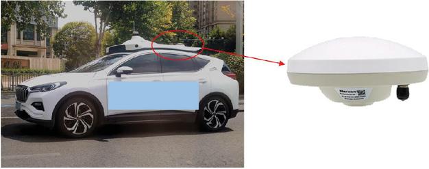
Figure 1 Schematic of AD-EV positioning system.
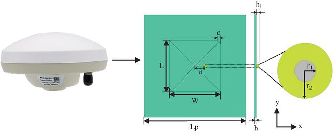
Figure 2 Structure of positioning antenna.
Table 1 Dielectric parameters of human tissue at 1.575 GHz
| Tissue | (S/m) | (kg/m) | C (J/kgC) | k (W/mC) | |
| Grey matter | 65.732 | 1.645 | 1044.5 | 3696 | 0.55 |
| White matter | 48.565 | 1.072 | 1041 | 3583 | 0.48 |
| Cerebellum | 60.692 | 2.060 | 1045 | 3653 | 0.51 |
| Skull | 25.544 | 0.676 | 1908 | 1313 | 0.32 |
| Heart | 77.952 | 2.109 | 1065.4 | 3651.5 | 0.54 |
| Liver | 58.104 | 1.519 | 1078.75 | 3540 | 0.52 |
| Lung | 64.714 | 1.507 | 394 | 3886 | 0.39 |
| Kidney | 71.712 | 2.340 | 1066.25 | 3763 | 0.53 |
| Stomach | 82.703 | 2.012 | 1088 | 3690 | 0.53 |
| Small intestine | 73.497 | 3.315 | 1030 | 3595 | 0.49 |
| Trunk | 46.264 | 1.251 | 1213 | 2818 | 0.38 |
Width and length of the antenna substrate are 100 mm, and relative permittivity is 3.38. The width of the square patch is determined by:
| (4) |
where is speed of light, is antenna wavelength, is operating frequency of the antenna.
In this study, the length (L) of the square patch is set equal to its width (W). Through calculation and according to the expected frequency, it is obtained that mm. Once the width of the substrate is established, the position of the feed point must be determined on the basis of the width, which affects the input impedance of the antenna. The feed point is located along the edge of the rectangular patch in the x-direction, the input impedance at is the highest, approximately ranging from 100 to 500 . On this basis, the position of the feeding point when the input impedance is 50 can be calculated. As shown in (5), is the position of the feed point in the x-direction when :
| (5) |
where is effective permittivity, which can be calculated by:
| (6) |
When the area S of the patch changes, the condition for the square microstrip antenna to obtain circularly polarized waves can be determined by:
| (7) | |
| (8) | |
| (9) |
where L is length of patch, W is width of patch, c is length of chamfer.
Based on the above, the antenna’s ground plane, radiating patch, inner conductor, and outer conductor of the coaxial cable are set as perfect electric conductors (PEC), and the relative permittivity of the isolator between the inner and exterior conductors is 2.1. Additionally, a perfectly matched layer (PML) is constructed outside the spatial computational domain as an absorbing boundary condition, simulating the propagation of electromagnetic waves radiated by the 1.575 GHz positioning antenna to infinity.
Table 2 presents the main geometric parameters of the antenna. By simulating the antenna model in COMSOL Multiphysics, the radiation characteristics of the antenna can be obtained. Figure 3 shows the curve of the parameter of the antenna. The optimal operating frequency of the antenna is 1.575 GHz, and the return loss is 17.95 dB, which meets the design requirements of the antenna.
Table 2 Parameters of positioning antenna
| Description | Parameter | Value (mm) |
| Substrate width | Lp | 100 |
| Substrate thickness | h | 1.524 |
| Patch length | L | 50.28 |
| Patch width | W | 50.28 |
| Chamfer | c | 3.5 |
| Inner conductor radius | r1 | 0.6 |
| Coaxial cable radius | r2 | 1.63 |
| Position | d | 10 |
| Coaxial cable height | h1 | 2 |
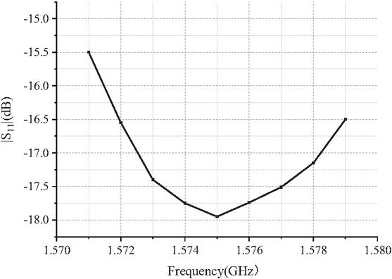
Figure 3 parameters of antenna.
Figure 4 shows the radiation pattern of the axial ratio of the designed antenna. Circularly polarized antennas emit circularly polarized waves during operation, and the axial ratio radiation pattern reflects the purity of these waves in different spatial directions. Figure 5 shows the three-dimensional far-field gain of the antenna, with a maximum gain of 6.8 dBi. All these meet the design requirements of a GNSS antenna. As shown in Table 3, a comparison between the antenna designed in this paper with those reported in other literatures demonstrates that the proposed antenna has excellent comprehensive performance and meets the design requirements for GNSS antennas. The positioning antenna shell of the roof of AD vehicles is generally a circular plastic shell structure, which has minimal impact on the radiation performance of the antenna, and can also protect the internal components from the external environment (such as rain, dust), waterproof, anti-ultraviolet and extend the service life of the antenna.
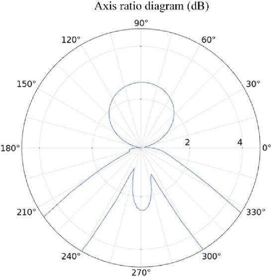
Figure 4 Axis ratio radiation pattern.
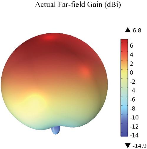
Figure 5 Antenna gain pattern.
Table 3 Comparison of antenna parameters in this work with other literatures
| Reference | Gain | Axial Ratio | |
| This Work | 6.8 dBi | 17.95 dB | 3 dB |
| [39] | 4.12 dBiC | — | 3 dB |
| [40] | 5.94 dBi | 30 dB | 2.5 dB |
| [41] | 4 dBi | 15 dB | 2 dB |
| [42] | 3.24 dBiC | 10 dB | 3 dB |
| [43] | 3.8 dBiC | 15 dB | 3 dB |
D. Finite element model
In this study, the child human body model is an 11-year-old girl from the Virtual Population models [44]. She has a height of 1.49 m and a weight of 34.0 kg. As shown in Fig. 6, three-dimensional modelling software is used to obtain the seated child human body model for calculation. This child human body model contains 10 major tissues, such as white matter, cerebellum, skull, lung and heart.
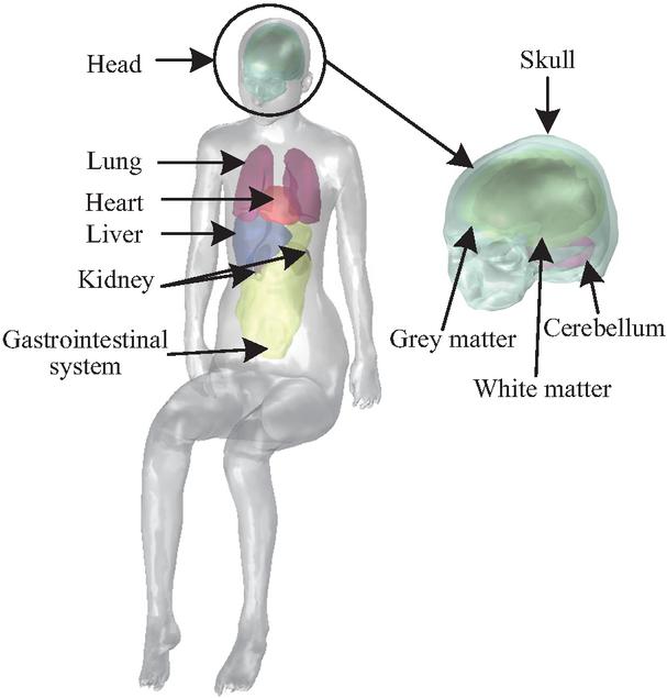
Figure 6 Child human body model.
Table 4 Main electrical parameters for the electric vehicle
| Material | (Relative ) | Relative Permeability () | Electrical Conductivity (, S/m) |
| Aluminum alloy | 1 | 1 | 2.326107 |
| Glass | 4 | 1 | 10-14 |
| Rubber | 2 | 1 | 10-9 |
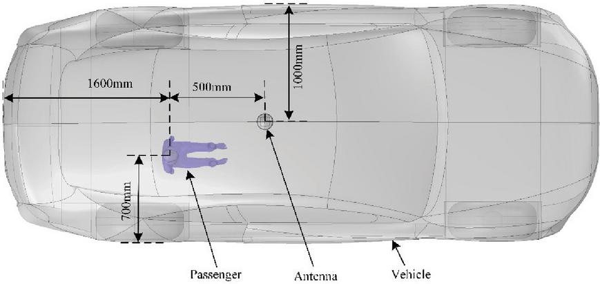
Figure 7 Relative position of human body and antenna.
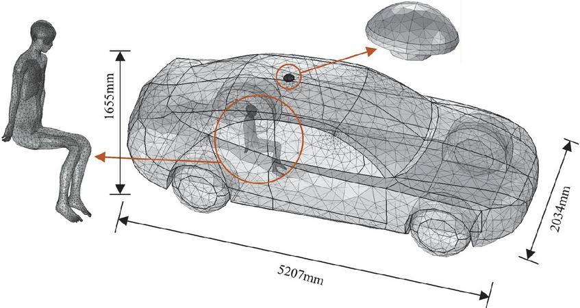
Figure 8 Finite element model.
In reference to a real AD vehicle, a proportional vehicle body model with the dimensions of 5207 mm 2034 mm 1655 mm is established in this study. When constructing the vehicle body model, some details that are irrelevant to electromagnetic calculations, such as license plates and internal components, are ignored to facilitate the division of finite element meshes and reduce the finite element calculation time [45]. The simplified model of the EV is composed of the body, windows and tires. Specifically, the body is made of aluminum alloy, the windows are made of glass, and the tires are made of rubber. The main electrical parameters of the different material are listed in Table 4 [46].
The vehicle body model, antenna model and child human body model are imported into COMSOL Multiphysics, and their spatial positions are shown in Fig. 8. As shown in Fig. 8, the finite element mesh division [47, 48] of the model is performed in COMSOL Multiphysics. A relatively fine mesh division is performed on the child human body model and the antenna model, resulting in a total of approximately 380,000 mesh grids. Moreover, the simulations conducted in this chapter involve large-scale computational. All calculations are performed on a computer equipped with an Intel Core Ultra 5 processor and 128 GB of RAM, with each simulation taking approximately 90 minutes to complete. Ultimately, all computational tasks are successfully finished.
E. Verification of the calculation methodology
COMSOL Multiphysics is based on the finite element method and can perform coupling analysis of multiple physical fields. In this study, the radio frequency module and temperature field module are used to couple the electromagnetic and thermal fields. The induced electric field, SAR and temperature rise in different tissues and organs of the child’s body are calculated for the electromagnetic exposure of positioning antenna.
To verify the accuracy of the research methods in this paper, a comparative validation was conducted with the results from [49]. This reference focuses on the electromagnetic exposure effects on the human body induced by a 400 MHz dipole antenna. Following the parameter configuration in this reference, a dipole antenna with a diameter of 1.0 millimeter and a length of 36.0 centimeters as the radiation source, with the output power set to 1 W, was placed at a distance of 8 centimeters from the human neck. Finally, the SAR of the human body was calculated. The comparative results are shown in Fig. 9 and Table 5.
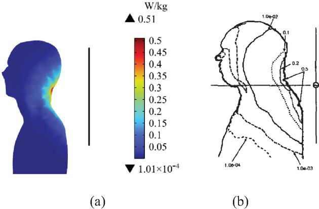
Figure 9 Comparison of SAR distribution in (a) this paper and (b) reference [49].
Table 5 SAR comparison and error analysis
| Results | Maximum SAR | Minimum SAR |
| This Work | 0.52 W/kg | 1.01 10-4 W/kg |
| Reference [49] | 0.51 W/kg | 1.00 10-4 W/kg |
| Error | 1.96% | 1.00% |
Numerical calculations show that the maximum SAR of the human body derived from COMSOL is 0.52 W/kg, with a relative error of approximately 1.96% compared with the result of 0.51 W/kg in [49]. Meanwhile, the calculated minimum SAR is 1.0110-4 W/kg, corresponding to a relative error of 1.00% compared to the result of 1.0010-4 W/kg in [49]. Since the calculated results are in good agreement with the reference, the application of COMSOL for calculating and analyzing human electromagnetic exposure levels in this study is reliable.
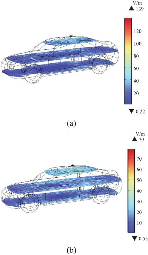
Figure 10 Electric field distribution on different cross-sections inside the vehicle: (a) vehicle body material set as air and (b) vehicle body material set as aluminum alloy.
III. RESULTS
A. Electric field distribution inside the EV body
Figure 10 (a) shows electric field distribution on different cross-sections inside the vehicle when the body area is equivalent to the air (i.e., free space). Figure 10 (b) shows electric field distribution at the same position when the body material is aluminum alloy. From Fig. 10 (a), it can be seen that electric field intensity shows a trend of gradual decrease from the antenna position to the surrounding area. Electric field distribution on different cross-sections inside the vehicle is relatively uniform, with a relatively high field intensity, and the maximum value is approximately 139 V/m. In contrast, when the vehicle body is aluminum alloy, the maximum field intensity at the corresponding positions decreases significantly to approximately 79 V/m. Therefore, it can be seen that the aluminum alloy vehicle body has a shielding effect on electromagnetic waves, enabling the rapid attenuation of the electric field inside the vehicle. This result fully demonstrates the significant value of metal materials in automotive electromagnetic protection.
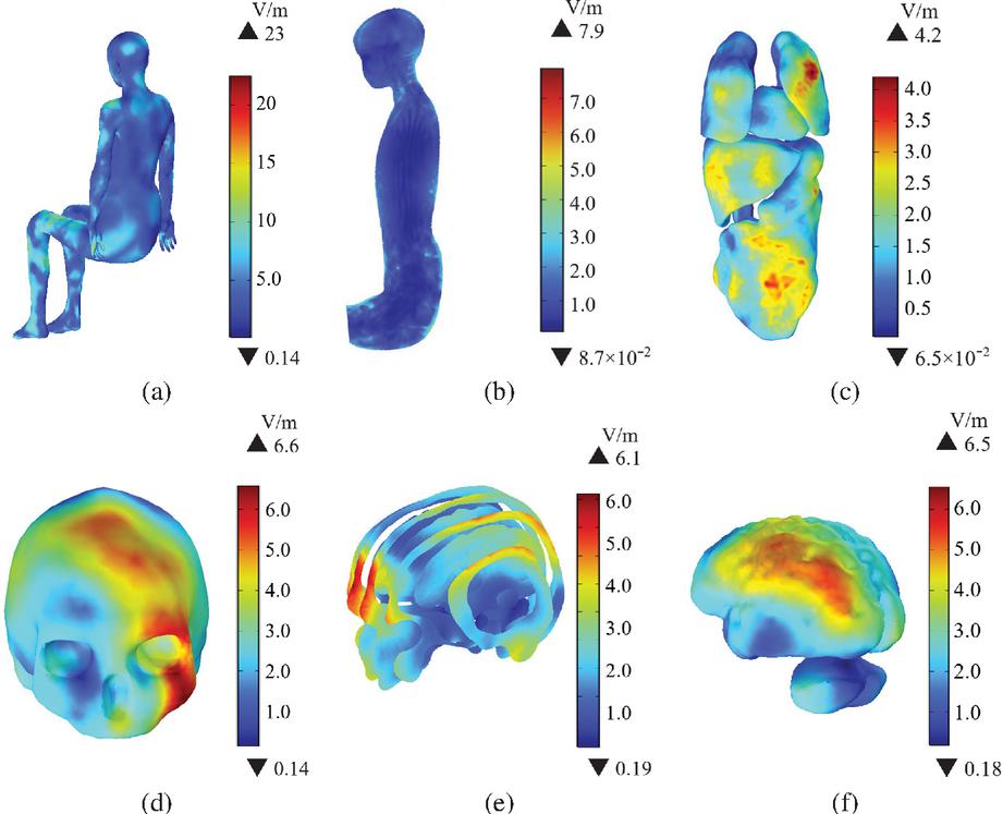
Figure 11 Induced electric field distributions in the child passenger’s body: (a) of the trunk, (b) of the longitudinal cross-section of the body, (c) of the different organs, (d) of the skull, (e) of the longitudinal cross-sections of the head, (f) of the brain tissue.
B. Distribution of induced electric field in a child’s body
Figure 11 shows distribution of the induced electric field in a child’s body. Figures 11 (a)–(b) are the distribution of in the child passenger’s trunk and central cross-section, respectively. The in the trunk is relatively uniform, with a maximum value of 23 V/m. The maximum value of induced electric field on the central cross-section of the child’s body is 7.9 V/m. Figure 11 (c) shows the in different major organs of the body. The is highest in the lungs, followed by the gastrointestinal system and the liver, while the in the kidneys is the smallest. The larger values of are distributed on the surfaces of the organs, with a maximum value of 4.2 V/m. Given the importance of the central nervous system, Figs. 11 (d)–(f) show the distribution of in the skull, and different longitudinal sections of the head and brain tissue, respectively. Brain tissue comprises grey matter, white matter, and the cerebellum, all of which are enclosed by the skull. The in the skull is slightly higher, with a maximum of 6.6 V/m. Given the protective effect of the skull, the in the brain tissue is relatively low, with a maximum of 6.5 V/m, and the higher values are mainly in the left-sided region of grey matter.
Figure 12 is the in different organs and tissues of the child passenger under the radiation of the positioning antenna. Given differences in dielectric properties and positions of various organs, the in different organs also varies. The in the head tissue is slightly higher than in other tissues, which can be attributed to the dielectric parameters of the tissue and the proximity to the exposure source. Among other organs, the of the lungs is slightly higher, slightly lower in the gastrointestinal system, followed by that of the liver and heart, while the kidneys have the smallest value.
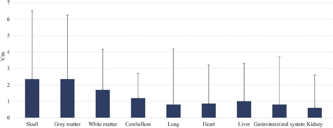
Figure 12 in different organs and tissues of the child passenger.
C. Distribution of SAR in the child’s body
When a RF EMF interacts with the human body, electromagnetic energy is absorbed by biological tissues. SAR is used to quantify the amount of electromagnetic energy absorbed by biological tissues. The power of the radiation source is a critical parameter for regulating SAR values. When the radiation frequency of the source and the electromagnetic property parameters of human tissue are fixed, the SAR values show a significant positive correlation with the input power: increased input power enhances the electromagnetic energy absorbed by human tissue, and SAR value rises accordingly. Conversely, reduced input power induces a decrease in SAR value. In this study, the SAR in different tissues of a child’s body is calculated to evaluate the exposure of child passengers to the RF electromagnetic environment generated by the positioning antenna.
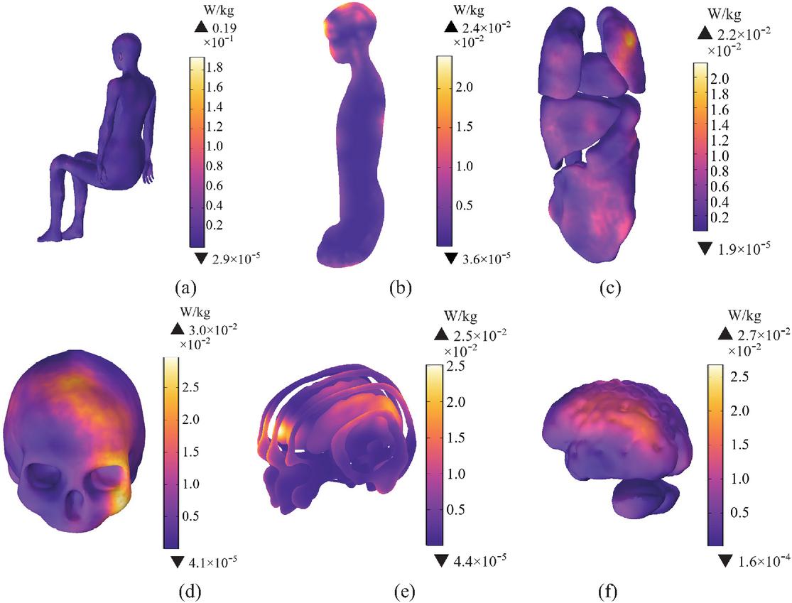
Figure 13 SAR1g distributions in the child passenger’s body: (a) SAR1g of the trunk, (b) SAR1g of the longitudinal cross-section of the body, (c) SAR1g of the different organs, (d) SAR1g of the skull, (e) SAR1g of the longitudinal cross-sections of the head, (f) SAR1g of the brain tissue.
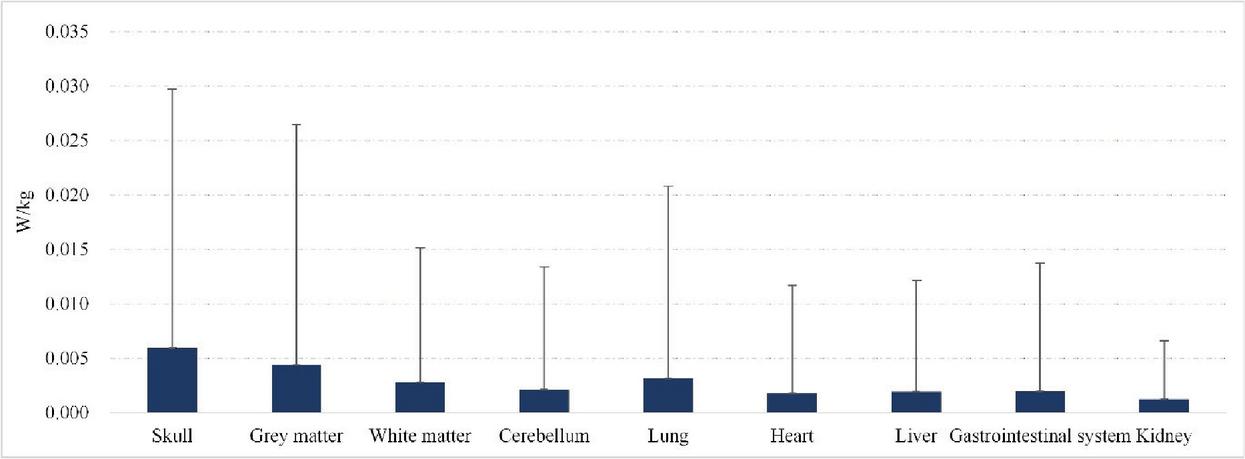
Figure 14 Maximum values of SAR1g in different organs and tissues of the child passenger.
Figures 13 (a)–(b) are SAR1g distribution in the child passenger’s trunk and central cross-section, respectively. SAR1g in the child passenger’s trunk is relatively uniform. The maximum values of SAR1g in the trunk and central cross-section are 0.19 W/kg and 2.410-2 W/kg, which remain below the safe limit for public exposure defined by the Federal Communications Commission’s (FCC) requirements [50]. Figure 13 (c) shows SAR1g in various organs of the child’s body, which demonstrates that the maximum values of SAR1g is primarily concentrated in the lungs with a maximum of 2.210-2 W/kg. Figures 13 (d)–(f) are SAR1g in the skull, and different longitudinal sections of the head and brain tissue, respectively. The left frontal area of the head is close to the antenna, and SAR is higher, with a maximum value of 3.010-2 W/kg. From the skull to the brain tissue, the SAR1g value decreases gradually, and the maximum values of SAR1g in the brain tissue is 2.710-2 W/kg. SAR1g is well below the safe limit of 1.6 W/kg for general exposure limit defined by the FCC’s requirements.
Figure 14 is the maximum values of SAR1g in the different organs and tissues of the child passenger. The maximum value of SAR1g in the brain tissue is approximately 2.710-2 W/kg, which is smaller than that in the skull. In other organs, SAR1g is the highest in the lungs, with a maximum of 2.210-2 W/kg, whereas SAR1g in the kidneys is lowest. The differences of SAR1g in different organs are due to electrical conductivity, tissue density and distance from the radiation source. Thus, the SAR1g for all organs and tissues in the child’s body remain below the general exposure limit of 1.6 W/kg defined by the FCC’s requirements [50]. By calculation, the average whole-body SAR for the child passenger is 0.0054 W/kg, below the general exposure limit of 0.08 W/kg defined by the FCC’s requirements.
D. Temperature rise in the child’s body
When exposed to RF EMFs, the electromagnetic energy absorbed by the human body causes the temperature to rise. To ensure that temperature increases remain within safe limits, the ICNIRP has defined the threshold of 1∘C as the limit for adverse health effects due to tissue temperature rise [51].
In this study, the initial temperature of the child’s body is set to 36.5∘C, and the temperature change is calculated within 30 minutes of exposure to the radiation from the positioning antenna. As shown in Figs. 16 (a)–(b), the maximum temperature rise in the child passenger’s trunk and central cross-section is 0.47∘C and 0.38∘C, respectively. Figure 16 (c) shows the temperature rise in different major organs. The temperature rise in the lungs is the biggest, with a maximum value of 0.55∘C, probably due to their lower density than other organs. Figures 16 (d)–(f) are the temperature rise in the skull, and different longitudinal sections of the head and brain tissue, respectively. The temperature rise of the skull is greater than that of the brain tissue, and the maximum temperature rise in the skull is 0.38∘C. The maximum temperature rise in the brain tissues is 0.27∘C.
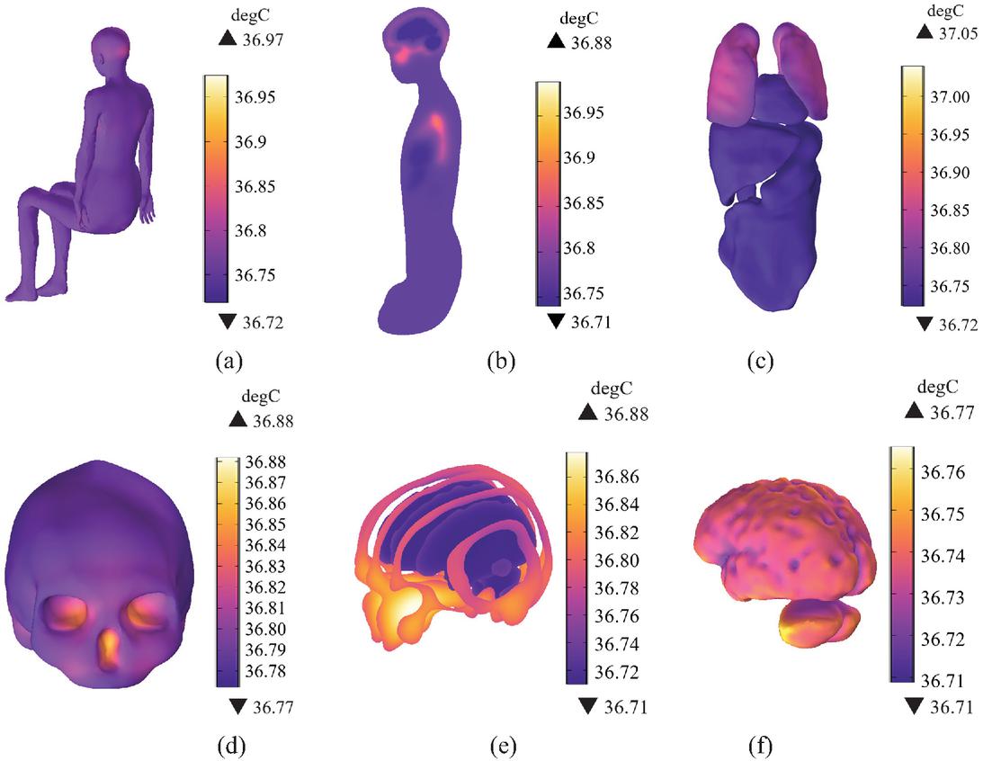
Figure 15 Temperature rise in the child passenger’s body: (a) temperature rise of the trunk, (b) temperature rise of the longitudinal cross-section of the body, (c) temperature rise of the different organs, (d) temperature rise of the skull, (e) temperature rise of the longitudinal cross-sections of the head, (f) temperature rise of the brain tissue.
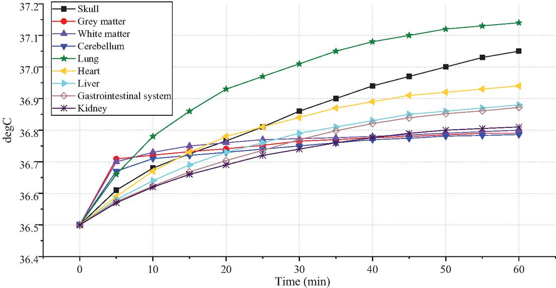
Figure 16 Temperature rise of different organs and tissues of the child passenger within 60 minutes.
Figure 16 is a comparison of temperature rise in different organs and tissues within 60 minutes under the radiation of the positioning antenna. The temperature of each organ increases rapidly in the early stage and then gradually stabilizes. In brain tissue, the temperature rise trends of grey matter, white matter, and the cerebellum are similar. The increase is fastest within the first 0-5 minutes, then gradually slows down. Over a 60-minute period, their temperature increase is also the smallest, all at approximately 0.3∘C. The temperature rise of the skull increases gradually within 60 minutes, reaching a maximum rise of 0.55∘C. Compared with other organs and tissues, the temperature rise in the lungs is the largest with a maximum of 0.64∘C. The rate of temperature rise of other organs within 60 minutes is relatively moderate, between 0.3∘C and 0.4∘C. In summary, the temperature rise in all tissues and organs of the child’s body remains below the ICNIRP limit of 1∘C [51].
IV. DISCUSSION
With the rapid development of EVs and AD technology, positioning antennas have been widely installed on AD vehicles. The body of a child passenger may be more sensitive to electromagnetic radiation because it is still growing and developing; thus, the electromagnetic radiation level of child passengers in EVs must be studied. Taking the positioning antenna of EV as the exposure source, this study constructed an electromagnetic environment model including the vehicle body, the positioning antenna and the child passenger model. COMSOL Multiphysics was used to calculate the electromagnetic environment of the positioning antenna with a frequency of 1.575 GHz and to quantify the exposure levels in different tissues and organs of the child passenger. The results show that in the child’s body is 23 V/m, and in the child’s brain is 6.6 V/m. Moreover, the maximum of SAR1g in the child’s body is 0.19 W/kg, the maximum of SAR1g in the child’s brain is 2.710-2 W/kg. The SAR1g levels calculated for the child models in this study are all below the safety limit of 1.6 W/kg defined by the FCC’s requirements. Within 30 minutes, the region of the child’s body with the maximum temperature rise is the lungs, with a maximum rise of 0.55∘C, while the maximum temperature rise in the head is 0.38∘C. The temperature rises calculated for the child models in this study are all below the safety limit of 1∘C defined by ICNIRP 2020. The distribution of induced field is slightly different due to different dielectric parameters of tissues and different positions with the exposure source. Therefore, the electromagnetic radiation generated by the positioning antenna does not pose a threat to the health of the child passenger. The calculation results of this study effectively supplement research on the electromagnetic environment of EVs and improve public cognition of the electromagnetic environment of EVs. In addition, it can provide reference for the revision of electromagnetic radiation standards and the optimization of positioning antenna design.
ACKNOWLEDGMENT
This work was supported by the National Natural Science Foundation of China (Grant No.52467026), the Natural Science Foundation of Gansu Province, China (Grant No. 23JRRA889), the Innovation Fund Project of Colleges and Universities in Gansu Province (Grant No. 2024B-057) and the Key Research Platform Construction Project of Gansu Province (Grant No. 2024CXPT-11).
REFERENCES
[1] R. Wu, “Research on the development trend of new energy electric vehicles in China based on mathematical model,” SJEMR, vol. 6, no. 10, pp. 26–33, Oct. 2024.
[2] J. N. Barkenbus, “Prospects for electric vehicles,” Sustainability, vol. 12, no. 14, pp. 5813, July 2020.
[3] K. Kaur and G. Rampersad, “Trust in driverless cars: Investigating key factors influencing the adoption of driverless cars,” J. Eng. Technol. Manage., vol. 48, pp. 87–96, Apr. 2018.
[4] J. L. Volakis, A. J. O’Brien, and C.-C. Chen, “Small and adaptive antennas and arrays for GNSS applications,” Proc. IEEE, vol. 104, no. 6, pp. 1221–1232, June 2016.
[5] X. Dong, Y. Ren, and M. Lu, “Electromagnetic exposure level of pure electric vehicle inverter to human body in different seating positions,” Radiat. Prot. Dosim., vol. 201, no. 4, pp. 270–283, Mar. 2025.
[6] Y. Hakuta, T. Watanabe, T. Takenaka, T. Ito, and A. Hirata, “Safety standard compliance of human exposure from vehicle cables using coupling factors in the frequency range of 0.3-400 kHz,” IEEE Trans. Electromagn. Compat., vol. 63, no. 1, pp. 313–318, Feb. 2021.
[7] T. Tan, T. Jiang, Y. Wu, Y. Zhu, and Y. Chi, “Safety assessment of gender-specific human electromagnetic exposure with aortic valve stents for EV-WPT,” Applied Computational Electromagnetics Society (ACES) Journal, pp. 742–753, Aug. 2024.
[8] T. Wang, B. Li, K. Zhao, and Q. Yu, “Evaluation of electromagnetic exposure of the human with a coronary stent implant from an electric vehicle wireless power transfer device,” Electronics, vol. 12, no. 20, p. 4231, Oct. 2023.
[9] V. Anderson, “Comparisons of peak SAR levels in concentric sphere head models of children and adults for irradiation by a dipole at 900 MHz,” Phys. Med. Biol., vol. 48, no. 20, pp. 3263–3275, Oct. 2003.
[10] T. Mo, Y. Li, K. Lau, C. K. Poon, Y. Wu, and Y. Luo, “Trends and emerging technologies for the development of electric vehicles,” Energies, vol. 15, no. 17, p. 6271, Aug. 2022.
[11] P. Moreno-Torres Concha, P. Velez, M. Lafoz, and J. R. Arribas, “Passenger exposure to magnetic fields due to the batteries of an electric vehicle,” IEEE Trans. Veh. Technol., vol. 65, no. 6, pp. 4564–4571, June 2016.
[12] N. Haussmann, R. Mease, M. Zang, S. Stroka, H. Hensel, and M. Clemens, “Efficient high-resolution electric and magnetic field simulations inside the human body in the vicinity of wireless power transfer systems with varying models,” COMPEL, vol. 42, no. 4, pp. 903–913, June 2023.
[13] I. A. Shah, Y. Cho, and H. Yoo, “Safety evaluation of medical implants in the human body for a wireless power transfer system in an electric vehicle,” IEEE Trans. Electromagn. Compat., vol. 63, no. 3, pp. 681–691, June 2021.
[14] J. Lin, M. Lu, T. Wu, L. Yang, and T. Wu, “Evaluating extremely low frequency magnetic fields in the rear seats of the electric vehicles,” Radiat. Prot. Dosim., vol. 182, no. 2, pp. 190–199, Dec. 2018.
[15] W. Yang, Y. L. Xu, C.Q. Wang, F.H. Lin, and L. Dong, “Research on the safety of human electromagnetic environment of wireless energy transfer locomotive,” Transactions of China Electrotechnical Society, vol. 37, no. 11, pp. 2665–2672, 2023.
[16] J. Wang, S. Mu, and Z. Hai, “Research on the influence of electromagnetic radiation in the automobile on the SAR value of human body,” J. Phys.: Conf. Ser., vol. 1684, no. 1, p. 012153, Nov. 2020.
[17] M. Y. Li and X. Zhang, “Modeling and electromagnetic safety assessment of wireless power transfer systems for electric vehicles,” J. Power Supply, vol. 21, no. 04, pp. 177–185, 2023.
[18] B. Pophof, B. Henschenmacher, D. R. Kattnig, J. Kuhne, A. Vian, and G. Ziegelberger, “Biological effects of radiofrequency electromagnetic fields above 100 MHz on fauna and flora: Workshop report,” Health Phys., vol. 124, no. 1, pp. 31–38, Jan. 2023.
[19] A. Bortkiewicz, “Health effects of radiofrequency electromagnetic fields (RF EMF),” Ind. Health, vol. 57, no. 4, pp. 403–405, 2019.
[20] M. I. Hossain, M. R. I. Faruque, and M. T. Islam, “Analysis on the effect of the distances and inclination angles between human head and mobile phone on SAR,” Prog. Biophys. Mol. Biol., vol. 119, no. 2, pp. 103–110, Nov. 2015.
[21] E. Baramili, R. Sarkis, and M. B. Saleh, “Investigation of driver EMF exposure from 4G/5G automotive glass mounted antennas,” in IEEE International Symposium on Antennas and Propagation and North American Radio Science Meeting, Montreal, QC, Canada, pp. 1451–1452, July 2020.
[22] G. Tognola, B. Masini, S. Gallucci, and M. Bonato, “Numerical assessment of RF human exposure in smart mobility communications,” IEEE J. Electromagn. RF Microw. Med. Biol., vol. 5, no. 2, pp. 100–107, June 2021.
[23] G. Tognola, M. Benini, M. Bonato, S. Gallucci, and M. Parazzini, “Assessment of the variability of human exposure to radiofrequency electromagnetic fields arising from 5.9 GHz vehicular communication in urban environments,” Sensors, vol. 23, no. 15, p. 6802, July 2023.
[24] S.-W. Leung, Y. Diao, K.-H. Chan, Y.-M. Siu, and Y. Wu, “Specific absorption rate evaluation for passengers using wireless communication devices inside vehicles with different handedness, passenger counts, and seating locations,” IEEE Trans. Biomed. Eng., vol. 59, no. 10, pp. 2905–2912, Oct. 2012.
[25] J. Malmivuo and R. Plonsey, Bioelectromagnetism Principles and Applications of Bioelectric and Biomagnetic Fields. Oxford: Oxford University Press, 1995.
[26] H. Sun, S. Hou, Y. Zhao, W. Yan, and Y. Wu, “Investigation of electromagnetic exposure of WPT coil to human body based on biological electromagnetic safety assessment,” Applied Computational Electromagnetics Society (ACES) Journal, vol. 36, no. 10, pp. 1355–1366, Nov. 2021.
[27] I. Liorni, C. Myles, W. Luuk, W. Joe, J. Wout, C. Elisabeth, G. Mònica, V. Roel, and T. Arno, “Evaluation of specific absorption rate in the far-field, near-to-far field and near-field regions for integrative radiofrequency exposure assessment,” Radiat. Prot. Dosim., vol. 190, no. 4, pp. 459–472, Oct. 2020.
[28] H. H. Pennes, “Analysis of tissue and arterial blood temperatures in the resting human forearm,” Journal of Applied Physiology, vol. 1, no. 2, pp. 93–122, Aug. 1948.
[29] S. Gabriel, R. W. Lau, and C. Gabriel, “The dielectric properties of biological tissues: III. Parametric models for the dielectric spectrum of tissues,” Phys. Med. Biol., vol. 41, no. 11, pp. 2271–2293, Nov. 1996.
[30] M. Thurai, V. D. Goodridge, R. J. Sheppard, and E. H. Grant, “Variation with age of the dielectric properties of mouse brain cerebrum,” Phys. Med. Biol., vol. 29, no. 9, pp. 1133–1136, Sep. 1984.
[31] A. Peyman and C. Gabriel, “Cole–Cole parameters for the dielectric properties of porcine tissues as a function of age at microwave frequencies,” Phys. Med. Biol., vol. 55, no. 15, pp. N413-N419, Aug. 2010.
[32] A. Peyman, A. A. Rezazadeh, and C. Gabriel, “Changes in the dielectric properties of rat tissue as a function of age at microwave frequencies,” Phys. Med. Biol., vol. 46, pp. 1617–1629, 2001.
[33] A. K. Lee, H. D. Choi, and J. I. Choi, “Study on SARs in head models with different shapes by age using SAM model for mobile phone exposure at 835 MHz,” IEEE Trans. Electromagn. Compat., vol. 49, no. 2, pp. 302–312, May 2007.
[34] X. Dong, Y. Qian, and M. Lu, “Electromagnetic exposure levels of electric vehicle drive motors to passenger wearing cardiac pacemakers,” Sensors, vol. 24, no. 13, p. 4395, July 2024.
[35] P. A. Hasgall, F. Di Gennaro, C. Baumgartner, and E. Neufeld, “IT’IS Database for thermal and electromagnetic parameters of biological tissues,” Version 3.0, Sep. 2015.
[36] Y. Fan, Z. Jin, Z. Fu, X. Cai, and Q. Lin, “Low-profile, broadband, and high-gain circularly polarized meta surface antenna using characteristic mode analysis,” Applied Computational Electromagnetics Society (ACES) Journal, vol. 40, no. 05, pp. 401–408, May 2025.
[37] S. S. Hao, Q. Q. Chen, J. Y. Li, and J. Xie, “A high-gain circularly polarized slotted patch antenna,” Antennas Wirel. Propag. Lett., vol. 19, no. 6, pp. 1022–1026, June 2020.
[38] C. L. Lin, Antenna Engineering Manual. Beijing: Publishing House of Electronics Industry, 2002.
[39] C. Sun, H. Zheng, and Y. Liu, “Analysis and design of a low-cost dual-band compact circularly polarized antenna for GPS application,” IEEE Trans. Antennas Propagat., vol. 64, no. 1, pp. 365–370, Jan. 2016.
[40] S. Mishra, S. Das, S. S. Pattnaik, S. Kumar, and B. K. Kanaujia, “Low-profile circularly polarized planar antenna for GPS L1, L2, and L5 bands,” Microw. Opt. Techn. Let., vol. 62, no. 2, pp. 806–815, Mar. 2020.
[41] L. Garcia-Gamez, L. Bernard, S. Collardey, H. Covic, R. Sauleau, K. Mahdjoubi, P. Potier, and P. Pouliguen, “Compact GNSS metasurface-inspired cavity antennas,” Antennas Wirel. Propag. Lett., vol. 18, no. 12, pp. 265–2656, Dec. 2019.
[42] H. Aliakbari, X. Li, C. Lötbäck, and B. K. Lau, “Roof-glass integrated antenna for vehicular GNSS applications,” in 18th European Conference on Antennas and Propagation, Glasgow, pp. 1–5, Mar. 2024.
[43] Q. H. Dang, N. Nguyen-Trong, T. Kaufmann, T. Saarnimo, C. Hide, and C. Fumeaux, “Dual-band circularly-polarized transparent GNSS antenna for vehicular applications,” IEEE Open J. Antennas Propag., vol. 6, no. 1, pp. 201–211, Feb. 2025.
[44] M. C. Gosselin, E. Neufeld, H. Moser, and E. Huber, “Development of a new generation of high-resolution anatomical models for medical device evaluation: The Virtual Population 3.0,” Phys. Med. Biol., vol. 59, no. 18, pp. 5287–5303, 2014.
[45] V. De Santis, L. Giaccone, and F. Freschi, “Influence of posture and coil position on the safety of a WPT system while recharging a compact EV,” Energies, vol. 14, no. 21, p. 7248, Nov. 2021.
[46] J. Grosinger, L. W. Mayer, C. F. Mecklenbrauker, and A. L. Scholtz, “Determining the dielectric properties of a car tire for an advanced tire monitoring system,” in IEEE 70th Vehicular Technology Conference Fall., Anchorage, AK, pp. 1–5, Sep. 2009.
[47] H.-Y. Kim and H.-G. Kim, “A hexahedral-dominant FE meshing technique using trimmed hexahedral elements preserving sharp edges and corners,” Eng. Comput., vol. 38, no. 5, pp. 4307–4322, Oct. 2022.
[48] A. Conchin Gubernati, F. Freschi, L. Giaccone, and R. Scorretti, “Analysis of numerical artifacts using tetrahedral meshes in low frequency numerical dosimetry,” Appl. Sci., vol. 12, no. 13, p. 6526, June 2022.
[49] A. Hirata, T. Fujino, and T. Shiozawa, “SAR in the human body due to EM waves emitted from a dipole antenna at 400 MHz band,” in IEEE International Symposium on Electromagnetic Compatibility, Istanbul, vol. 1, pp. 17–20, 2003.
[50] X. Hu, S. Yan, J. Zhang, V. Volski, and G. A. E. Vandenbosch, “Omni-directional circularly polarized button antenna for 5 GHz WBAN applications,” IEEE Trans. Antennas Propagat., vol. 69, no. 8, pp. 5054–5059, Aug. 2021.
[51] ICNIRP, “Guidelines for limiting exposure to electromagnetic fields (100 kHz to 300 GHz),” Health Phys., vol. 118, no. 5, pp. 483–524, May 2020.
BIOGRAPHIES

Xuwei Dong received the Ph.D. degree from Lanzhou Jiaotong University, Lanzhou, China, in 2019. He is an associate professor at Lanzhou Jiaotong University. He has successively undertaken or participated in the National Natural Science Foundation project of China. His main research fields are biomedical electromagnetism and electromagnetic exposure safety assessment.

Yufei Ren received the B.S. degree in communication engineering from Henan University, Zhengzhou, China, in 2023. She is currently pursuing the master’s degree at Lanzhou Jiaotong University. Her work centers on evaluating the safety of RF-EMF exposure and biomedical electromagnetism.

Mai Lu received the Ph.D. degree from Lanzhou University, Lanzhou, China in 1999. He is a professor at Lanzhou Jiaotong University, Lanzhou. He has successively undertaken or participated in the UK EPSRC project, the seventh EU framework agreement project, and the National Natural Science Foundation project. His main research fields are biomedical electromagnetism and electromagnetic exposure safety assessment.
ACES JOURNAL, Vol. 41, No. 3, 244–257
DOI: 10.13052/2026.ACES.J.410306
© 2026 River Publishers