A High-Precision Beamforming Reflectarray Using an Improved Hybrid PSO-GA Algorithm and Low-Coupling Element
Ren Jiawei and Li Zuowen
Artificial Intelligence and Human Language Lab
Beijing Foreign Studies University, Beijing 100089, China
22053@bfsu.edu.cn, lizuowen@bfsu.edu.cn
Submitted On: May 28, 2025; Accepted On: March 12, 2026
Abstract
This paper proposes a high-precision cosecant square beamforming reflectarray using an improved hybrid Particle Swarm Optimization and Genetic Algorithm (PSO-GA) and low-coupling square ring element. Firstly, a novel hybrid PSO-GA algorithm is carried out to optimize the phase distribution of the high-precision beamforming reflectarray. Then, an element is presented whose reflection phase is insensitive to different incident angles and reflection amplitude stable with variations of element size. By using the above-mentioned methods, a high-precision beamforming reflectarray is designed and analyzed. The experimental results show well-defined cosecant squared beams in the predefined direction are achieved in the frequency range from 13.1 to 14.3 GHz and have low loss.
Index Terms: Beamforming reflectarray, optimization, reflectarray antenna.
I. INTRODUCTION
Reflectarray antennas combine many of the favorable traits of both reflectors and phased arrays while minimizing many of the drawbacks of the two. Reflectarray antennas are a low-profile, lightweight, and planar high-gain alternative to the conventional large and bulky parabolic reflectors and phased array antennas [1, 2, 3, 4]. Reflectarrays can perform beamforming while remaining planar. Due to the lack of feed network, it also ensures a much greater efficiency for the reflectarrays compared with the phased array antennas.
A shaped-beam reflectarray with a cosecantsquared pattern was first presented in [5]. A narrowband reflectarray making use of a single layer of varying-sized patches is shown in [6], providing a European coverage. Reflectarray antennas have also been used to provide accurate shaped beams by using a flat sandwich with printed patches appropriately optimized [7, 8]. In [9], Particle Swarm Optimization (PSO) and Genetic Algorithm (GA) are compared and it is inferred that the convergence of PSO is faster than that of GA to the desired radiation pattern.
Evolutionary Algorithms (EAs) such as GA and PSO are effective and flexible techniques able to optimize multi-modal and non-convex cost functions like those modelling in general many engineering problems, and more specifically antennas ones [10, 11, 12, 13]. For less complex problems, it demonstrates some advantages over the Back Propagation (BP) Neural Network algorithm [14]. Although the heuristic mentioned algorithms have been widely utilized as optimization tools, there are also some demerits, such as trapping of the local optimum [15], low accuracy, and early-maturing problems.
In reflectarrays, the array elements are designed with varying sizes [16] or rotation angles [17] to provide the desired phase distribution. Therefore, each element exhibits different mutual coupling levels and works at different resonance states, which leads to difficulties in the designing of high-precision beamforming reflectarrays.
This paper presents a high-precision beamforming reflectarray based on an improved hybrid PSO-GA algorithm and a low-coupling square ring element. First, an improved PSO-GA algorithm and a robust element design are proposed, featuring incident-angleinsensitive phase stability and minimal reflection amplitude fluctuation across size variations, which collectively reduce phase errors and enhance reflectarray performance. Next, a high-precision reflectarray antenna using these methods is designed, measured, and analyzed. Finally, key conclusions are summarized.
II. PROPOSED APPROACH
A. An improved hybrid PSO-GA algorithm for calculation of phase distribution of the reflectarray
In order to obtain phase distribution of the shaped beam reflectarray, an improved hybrid PSO-GA algorithm is proposed. It combines the advantages of PSO and GA. It is a heuristic optimization technique that is robust and efficient in solving antenna problems.
The flow chart of the improved hybrid PSO-GA algorithm is shown in Fig. 1.
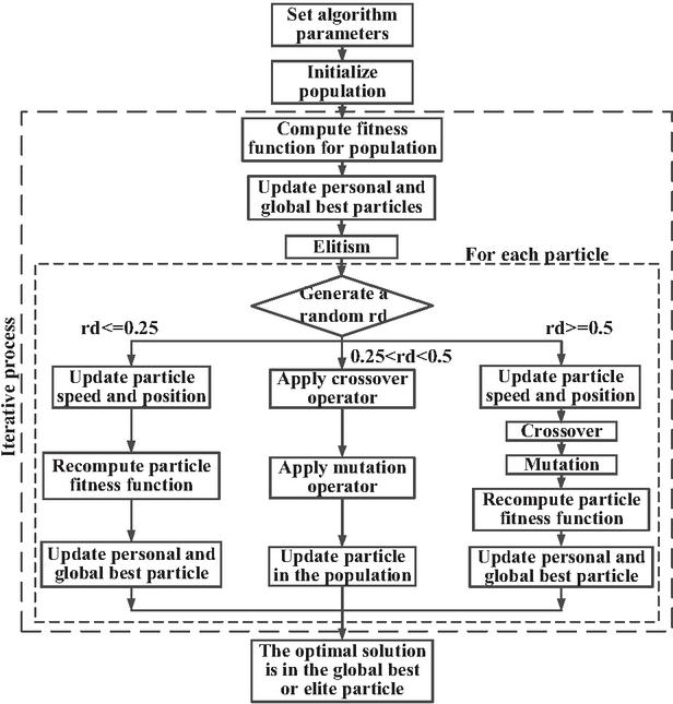
Figure 1 Flow chart of the improved hybrid PSO-GA algorithm.
The specific procedure of the hybrid PSO-GA algorithm is as follows:
Step 1: Set algorithm parameters and initialize particle swarm. Set the node number of particle swarm as . Let be the position vector of th particle, be the velocity vector, be the best position that particle has gone through, which can also be denoted as be the index numbers of best position that all particles has gone through, so , i.e. . Set the maximum velocity , learning factors and , inertia weight , maximum iteration times , solution precision value , crossing probability and mutation probability .
Step 2: Calculate the fitness function value of each particle. Select the particle with the optimal fitness value. Store and update the position of the particle in the optimal position of the particle . Compare all the values . Store and update the optimal adaptation value and the position of the particle in the optimal position of the group .
Step 3: In each iteration, when an individual is selected for update, a random number is generated, ranging from 0 to 1.
Step 4.1: If , the original PSO algorithm is used. Update the velocity and position of the particles by (1) and (2), then update the adaption value of particle:
| (1) | |
| (2) |
where represents evolution times, and are quasi-random numbers generated within . To prevent the velocity of the particle becoming too quick in the iteration, the velocity of the particle should be restricted in interval .
Step 4.2: If , then pure GA is used. Firstly, the crossing operation: choosing a set of particles with better adaption, which are matched by pairs in random. Crossing operation is carried out according to the certain probability . For those matched particles and , the crossing process is shown as follows:
| (3) | ||
| (4) |
where is random number in interval . Detecting the adaption value of every particle, the particles of weaker adaption value are made mutation operation by a certain probability :
| (5) |
where randn is a normal random integer and is a constant value . Then update the adaption value of the particle.
Step 4.3: If , the hybrid PSO-GA algorithm is used to obtain the phase distribution of beamforming reflectarray. The operations of selecting and crossing GA are introduced into PSO such that the information among the particles can be shared and convergence rate of particle swarm can be quickened. Using (1) and (2), update the position and velocity information of the particle. Using (3), (4) and (5), compare the adaption value of son-particle and that of father-particle. The particle with better adaption value should be left for the next iteration.
Step 5: Judge whether the maximum number of iterations has been reached or whether the best fitness value of the particle swarm has achieved the given accuracy. If so, the iteration process terminates and the result is output. Otherwise, return to Step 2 until the final result is obtained.
The proposed improved hybrid PSO-GA systems can find a better solution without trapping in local optimum solutions and achieve a faster convergence rate. When the PSO particles stagnate, GA diversifies the particle position even though the solution is worse. In PSO-GA, particle movement uses randomness in its search. Hence, it is a kind of stochastic optimization algorithm that can search a complicated and uncertain area.
B. Optimization of the phase distribution of the cosecant square beamforming reflectarray
To generate a cosecant beam with requirements on the pattern at levels 2 dB below the maximum, the phase distribution of a square cosecant beamforming reflectarray antenna at center frequency of is proposed in this section. The reflecting surface consists of unit cells, and the period of the element is chosen to be . Classically, lossless elementary antennas have a reflection magnitude of 0 dB and the phase distribution of planar reflectarray antennas by adjusting only the phase.
The radiation pattern obtained by the proposed algorithm is shown in Fig. 2 (a). Traditional PSO and GA are also used to obtain the phase distribution of the shaped beam reflectarray. Comparison of the cost function values of all three algorithms against the number of iterations is shown in Fig. 2 (b). As can be seen, both PSO and the improved hybrid PSO-GA algorithm exhibit faster convergence than GA. This is because PSO updates the evolutionary direction based on current optimal particles, which provides enhanced directional guidance. However, PSO tends to trap in local optima in the later stages. GA has a better global optimization capability and high-precision because it can effectively escape local optima through operations such as crossover and mutation, but it has a low convergence speed compared with PSO. Compared with PSO and GA, the results obtained using the improved hybrid PSO-GA algorithm is able to reach global optima of the phase distribution of the reflectarray, and this hybrid method improves the precision and efficiency of the model.
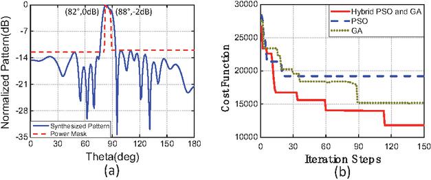
Figure 2 (a) Radiation pattern obtained by the proposed algorithm and (b) comparison of convergence speed of three algorithms.
Phase distribution obtained by the improved hybrid PSO-GA algorithm is shown in Table 1.
Table 1 Phase distribution obtained by the improved hybrid PSO-GA algorithm
| No. | Phase | No. | Phase |
| 1 | 184.8935 | 12 | 184.6788 |
| 2 | 259.3447 | 13 | 220.9182 |
| 3 | 59.6594 | 14 | 208.4418 |
| 4 | 266.4084 | 15 | 239.4929 |
| 5 | 27.57922 | 16 | 250.0374 |
| 6 | 251.1031 | 17 | 287.8221 |
| 7 | 65.75094 | 18 | 265.2022 |
| 8 | 193.9426 | 19 | 303.5217 |
| 9 | 117.6788 | 20 | 254.5281 |
| 10 | 163.933 | 21 | 356.9709 |
| 11 | 146.8121 | 22 | 299.101 |
C. Design and analysis of a low-coupling square ring element
To design a high-precision beamforming reflectarray, an element which has a low loss and the phase shift produced by the cell is nearly insensitive to the angle of incidence variations for angles up to is presented in this section. The geometry of the unit cell is shown in Fig. 3.
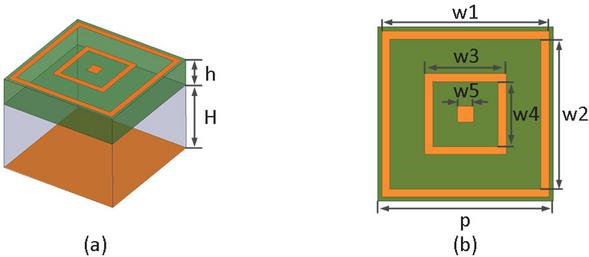
Figure 3 Geometry of the element.
The proposed element consists of two square rings and a square patch printed on the same side of a RT 5880 substrate with thickness of mm which is separated from a ground plane by an air layer with thickness of mm. The period of the element is chosen of mm. The length of outer side of the outer ring is , and the inner side is . The length of outer side and inner side of the middle ring are and , respectively, and the length of the inner square patch is . The phase of the reflected field is adjusted by changing the length of the variable mm). The lengths of and in the unit cell are adjusted to improve the bandwidth of the reflectarray.
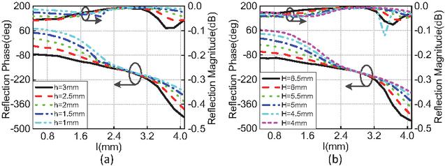
Figure 4 Simulated reflection phase and amplitude versus length for (a) different thickness of dielectric layer and (b) different air thickness .
Figures 4 (a) and (b) show the phase-shift and amplitude versus the variable length for different thickness of the dielectric layer and different air thickness at 13.88 GHz when one parameter is changed and another parameter is unchanged. It can be seen from Figs. 4 (a) and (b) that both and have some effects on the reflection phase and amplitude. Based on the linearity of the reflection phase curve and the smoothness of the reflection amplitude, the thicknesses of the medium and air layer have been chosen as mm and mm, respectively.
Next, the effect of the length of over the reflection phase and amplitude versus the length for different incident angle is studied as shown in Fig. 5 (a). It can be seen that, as increases, the phase response variation for different incident angles () also increases, primarily due to the coupling between adjacent elements and the resonance of the element. The lower the coupling between adjacent elements, the less influence on the phase shift for different incident angles. It can also be observed that has little effect on the reflection amplitude. Considering the phase shift and amplitude variations under different incident angles, the value of has been set to mm.
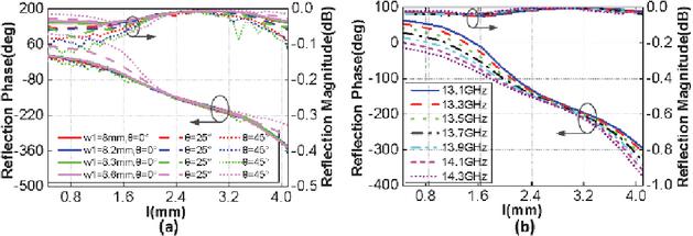
Figure 5 (a) Simulated phase shift and amplitude versus length for different lengths and incident angles and (b) simulated phase shift and amplitude versus length for normal incidence at different frequencies.
Figure 5 (b) plots the phase and magnitude of the reflection as functions of for normal incidence at different frequencies. As shown in Fig. 5 (b), the reflection phases versus plots are linear at different frequencies, and the amount of delayed phase increases as the frequency rises from 13.1 to 14.3 GHz. The losses of the reflection magnitude are lower than 0.05 dB within this frequency band. The final parameter values of the reflectarray antenna element are summarized in Table 2.
Table 2 Detailed parameters of the unit cell
| Parameter | Value | Parameter | Value |
| 8.6 mm | |||
| 8.2 mm | 0.8 mm | ||
| 7.4 mm | 2 mm | ||
| 5 mm | |||
III. DESIGN AND PERFORMANCE OF A SQUARE COSECANT BEAMFORMING REFLECTARRAY ANTENNA
A center-fed high-precision beamforming reflectarray consisted of elements based on the analysis above is designed as shown in Fig. 6. The antenna is designed for the operating frequency of 13.88 GHz and the square aperture of the reflectarray is 189.2 mm. The phase distribution in Table 1 is used for the design of the reflectarray to provide the required shaped beam: pencil in azimuth and squared cosecant in elevation. In order to reduce the variation of the phase shift of the element for different incident angles, a larger focal length is used, which indicates a ratio of 1.2.
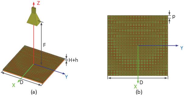
Figure 6 Prototype of beamforming reflectarray.
A prototype of the feed and the reflectarray is shown in Fig. 7 (a). The reflectarray was simulated in a full wave EM simulation and was measured by the NSI planar near-field system as shown in Fig. 7 (b).
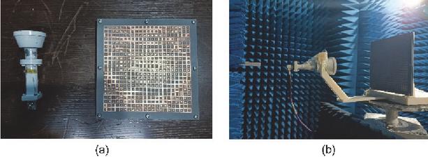
Figure 7 (a) Photograph of feed antenna and reflectarray and (b) near-field measurement.
The simulated and measured radiation patterns of the reflectarray at different frequencies are shown in Fig. 8. And the simulated polar radiation patterns of the reflectarray at 13.88 GHz is shown in Fig. 9. In all of the cosecant square regions, well-defined cosecant squared beams in the predefined direction are achieved and good agreement between the simulated and measured results is achieved in the frequency range from 13.1 to 14.3 GHz. However, discrepancies in sidelobe levels exist, primarily due to the scattered field on the reflectarray edges.
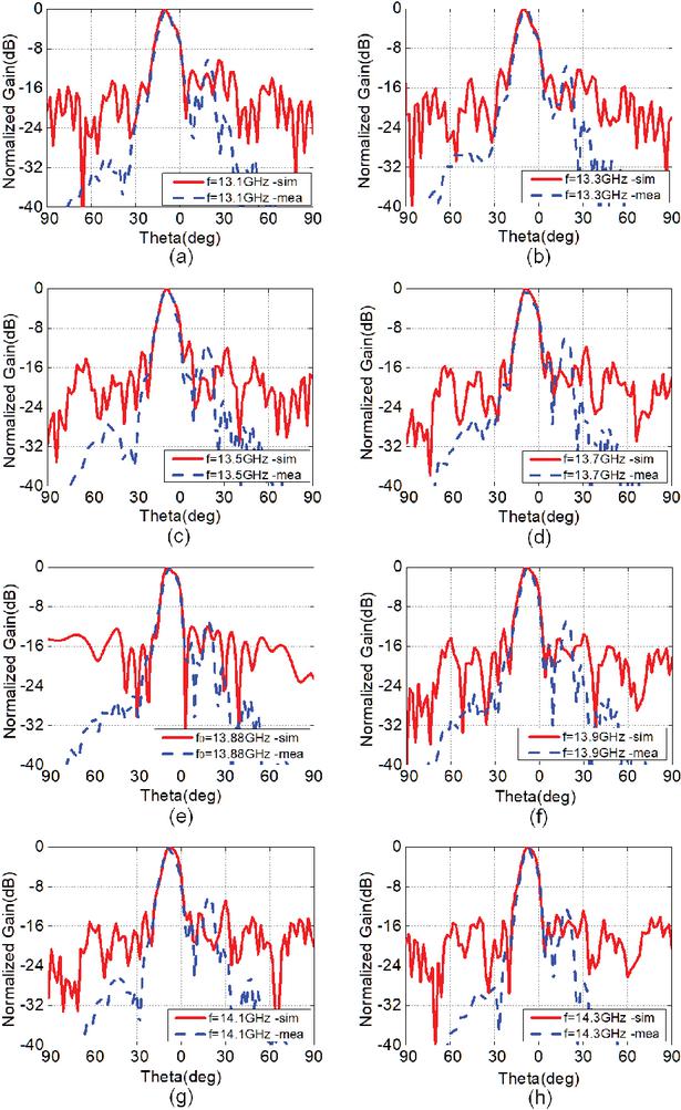
Figure 8 Simulated and measured radiation patterns of the reflectarray at (a) 13.1 GHz, (b) 13.3 GHz, (c) 13.5 GHz, (d) 13.7 GHz, (e) 13.88 GHz, (f) 13.9 GHz, (g) 14.1 GHz and (h) 14.3 GHz.
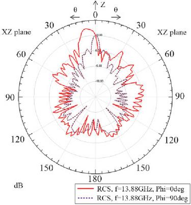
Figure 9 Simulated polar radiation patterns of the reflectarray at 13.88 GHz.
The simulated and measured gains and aperture efficiencies of the proposed reflectarray are shown in Fig. 10. It can be observed that the measured gain is consistently lower than the simulated gain. The simulated gain is increased from 21.2 to 23.7 dB as the working frequency increases from 12.5 to 14.5 GHz with a bandwidth of 8.6% (13.3–14.5 GHz) and the measured gain is from 18.3 to 22.6 dB with 1-dB bandwidth of 8.6% (13.3–14.5 GHz). The difference between the simulated and measured gains is attributed to the fabrication and measurement errors. The substrate of the element may distort during fabrication, causing errors in the phase compensation of the element. Other errors are introduced by blockage and misalignment of the feed. The aperture efficiencies of the reflectarray are also plotted in Fig. 10. The simulated and measured efficiencies vary from 36.6–39.2% and 31.7–37.4%, respectively. Although the 1 dB gain bandwidth of the reflectarray is 8.6%, some discrepancies exist between the simulated and measured radiation patterns and gains, which can be attributed to fabrication and measurement tolerances. Nevertheless, well-defined cosecant-squared beams in the predefined direction are maintained across the entire operating band, as shown in Fig. 8. This result demonstrates the strong robustness of the phase distribution optimized by our proposed algorithm against phase errors. Such bandwidth performance is highly competitive for a high-gain, shaped-beam reflectarray.
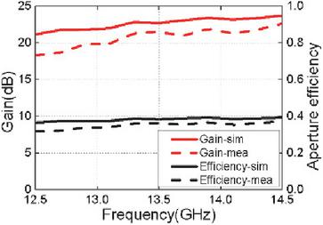
Figure 10 Simulated and measured gains and aperture efficiencies.
IV. CONCLUSION
This paper designs a high-precision shaped beam reflectarray using phase only control to achieve a cosecant squared beam. First, an improved hybrid PSOGA algorithm is proposed. Simulation results show that the hybrid algorithm outperforms PSO and GA in convergence speed and global optimization. The second part of this paper proposes an element whose reflection phase is insensitive to different incident angles and reflection amplitude keep stable with variation of element size. Finally, a high-precision beamforming reflectarray is designed using these methods. The simulation and measured results show that well-defined cosecant squared beams in the predefined direction are achieved in the frequency range from 13.1 to 14.3 GHz, which validates the effectiveness of the proposed approach.
ACKNOWLEDGMENT
This work was sponsored by the Central Universities Basic Research Operating Expenses Project of China under Grant 2023JJ008; in part by the Young Academic Innovation Team Project of Beijing Foreign Studies University under Grant 2023TD001.
REFERENCES
[1] J. Huang and J. A. Encinar, Reflectarray Antenna. Hoboken, NJ, USA: Wiley, 2007.
[2] Y. H. Cho, W. J. Byun, and M. S. Song, “High gain metal-only reflectarray antenna composed of multiple rectangular grooves,” IEEE Trans. Antennas Propag., vol. 59, no. 12, pp. 4559–4568, 2011.
[3] R. S. Malfajani and Z. Atlasbaf, “Design and implementation of a broadband single layer circularly polarized reflectarray antenna,” Antennas Wireless Propag. Lett., vol. 11, pp. 973–976, 2012.
[4] J. Ruze, “Aperture tolerance theory: A review,” in 1965 Antennas and Propagation Society International Symposium, pp. 210–210, 1965.
[5] D. C. Chang and M. C. Huang, “Feasibility study of erecting cosecant pattern by planar microstrip reflectarray antenna,” in Proc. AMPC’93, vol. 2, pp. 19.20–19.24, 1993.
[6] D. M. Pozar, S. D. Targonski, and R. Pokuls, “A shaped-beam microstrip patch reflectarray,” IEEE Trans. Antennas Propag., vol. 47, pp. 1167–1173, 1999.
[7] M. Arrebola, J. A. Encinar, and M. Barba, “Multifed printed reflectarray with three simultaneous shaped beams for LMDS central station antenna,” IEEE Trans. Antennas Propag., vol. 56, pp. 1518–1527, 2008.
[8] J. A. Encinar, M. Arrebola, L. F. de la Fuente, and G. Toso, “A transmit-receive reflectarray antenna for direct broadcast satellite applications,” IEEE Trans. Antennas Propag., vol. 59, no. 9, pp. 3255–3264, 2011.
[9] D. W. Boeringer and D. H. Werner, “Particle swarm optimization versus genetic algorithms for phased array synthesis,” IEEE Trans. Antennas Propag., vol. 25, no. 3, pp. 771–779, 2004.
[10] J. M. Johnson and Y. Rahmat-Samii, “Genetic algorithm optimization and its application to antenna design,” IEEE Xplore, vol. 1, pp. 326–329, 1994.
[11] D. Olcan, R. Golubovic, and B. Kolundzija, “On the efficiency of particle swarm optimizer when applied to antenna optimization,” IEEE Int. Antennas and Propag. Symposium, pp. 3297–3300, 2006.
[12] F. Grimaccia, M. Mussetta, P. Pirinoli, and R. E. Zich, “Optimization of a reflectarray antenna via hybrid evolutionary algorithms,” in 2006 17th International Zurich Symposium on Electromagnetic Compatibility, Singapore, pp. 254–257, 2006.
[13] A. Sheikholeslami and Z. Atlasbaf, “Novel phase distributions for large electronically beamscanning reflectarrays,” Scientific Reports, vol. 11, no. 1, p. 21877, 2021.
[14] S. Du, W. Li, and K. Cao, “A learning algorithm of artificial neural network based on GA-PSO,” in 2006 6th World Congress on Intelligent Control and Automation, vol. 1, 2006.
[15] S. Mesloub and A. Mansour, “Hybrid PSO and GA for global maximization,” Int. J. Open Problems Compt. Math., vol. 2, no. 4, pp. 597–608, 2009.
[16] L. Chang and S. V. Hum, “An electronically tunable single-layer reflectarray antenna element with improved bandwidth,” Antennas Wireless Propag. Lett., vol. 9, pp. 1241–1244, 2010.
[17] J. Huang and R. J. Pogorzelski, “A Ka-band microstrip reflectarray with elements having variable rotation angles,” IEEE Trans. Antennas Propag., vol. 46, pp. 650–656, 1998.
BIOGRAPHIES

Ren Jiawei was born in Hebei, China, in 1992. He received the B.S. degree from the Hebei University, Hebei, and the M.S. and Ph.D. degrees from the University of Chinese Academy of Sciences, Beijing, and Nation Space Science Center, Chinese Academy of Sciences, Beijing. His current research interests include reflectarray, microstrip antennas, lowloss antenna, and wideband antenna.

Li Zuowen is a professor and doctoral supervisor, currently serving as director of the Key Laboratory of Artificial Intelligence and Human Language at Beijing Foreign Studies University, China. He received his doctoral degree from Shanghai International Studies University and conducted post-doctoral research at Peking University. His current research interests include artificial intelligence and natural language processing.
ACES JOURNAL, Vol. 41, No. 3, 238–243
DOI: 10.13052/2026.ACES.J.410305
© 2026 River Publishers