Optimized Design of Shielding Structure for High Offset Tolerance WPT System Based on Fused Uncertainty Surrogate Model
T. H. Wang, K. F. Zhao, H. W. Duan, G. Lv, Q. Y. Yu, and S. S. Guan
College of Instrumentation & Electrical Engineering
Jilin University, Changchun 130026, China
wangtianhao@jlu.edu.cn, zhaokf23@mails.jlu.edu.cn, duanhw24@mails.jlu.edu.cn, lvgang23@mails.jlu.edu.cn, qyyu20@mails.jlu.edu.cn, guanshanshan@jlu.edu.cn
Submitted On: June 07, 2025; Accepted On: October 25, 2025
ABSTRACT
In the practical application of wireless power transfer (WPT), an offset between the coupling mechanisms can lead to an increase in harmful leakage of magnetic fields around the system and a decrease in the efficiency of energy transfer. In this paper, we propose to use the uncertainty quantitative surrogate model to guide optimal design of the shielding structure in order to reduce the leakage magnetic field and improve energy transfer efficiency, taking into account the positional offsets of the WPT system in use. In this paper, the uncertainty of the leakage magnetic field and the energy transfer efficiency of the WPT system is quantified based on the improved Transformer surrogate model of the Kolmogorov-Arnold Network, and computational time cost is reduced by 90.97%. The multi-objective exponential distribution optimizer is combined with a surrogate model to obtain the robust optimal structure under the influence of bias. Finally, it is experimentally verified that the robust optimal structure is able to maintain both low leakage magnetic field and high energy transfer efficiency under the influence of offset. Compared with the traditional deterministic optimal structure, the mean of the energy transfer efficiency of the robust optimal structure is increased by 4.95%, and the probability of overrun is reduced to 0. Experiments demonstrate that the robust structure can improve the offset tolerance of the system more effectively and ensure the electromagnetic safety of users at the same time.
Keywords: Exponential distribution optimizer, robust optimization, transformer, uncertainty quantification, wireless power transfer.
I. INTRODUCTION
Electromagnetic safety issues generated during the operation of wireless power transmission (WPT) are current research hotspots in the field of WPT. WPT technology realizes safe and convenient charging, which is widely used in the fields of medical devices [1], electric bicycles [2], unmanned aerial vehicles [3], and electric vehicles [4, 5, 6]. However, the energy transfer structure of the WPT system is a loosely coupled form, which inevitably generates leakage electromagnetic fields (LMF) during operation, thus the energy transfer efficiency becomes lower. In addition, due to the effect of offset uncertainty between the coupling mechanisms of the WPT system in the actual application process, the operating state of the system also has uncertainty [7, 8]. To ensure the safety of WPT products in use, the International Commission on Non-Ionizing Radiation Protection (ICNIRP) and the Institute of Electrical and Electronics Engineers (IEEE) have developed LMF standard limits for WPT systems to guide electromagnetic safety assessment [9, 10, 11]. Among them, ICNIRP uses the operating frequency of WPT systems as the basis for division and establishes limit values for different frequency bands for guidance. The WPT system used in this paper operates at a frequency of 85 kHz, with magnetic flux density in the environment serving as the evaluation target for the electromagnetic safety of the WPT system. Therefore, it is necessary to design a reasonable electromagnetic shielding structure so as to limit the LMF caused by the uncertainty of the operating state of the WPT system, in order to improve the electromagnetic safety and energy transfer efficiency of the WPT system [12, 13].
Various electromagnetic active and passive shielding measures have been proposed for LMF of WPT systems. Among them, passive shielding is highly flexible, secure, adaptable to the environment, and used in a wide range of scenarios [14, 15]. The use of transmitting or receiving coils in combination with aluminum plates and ferrite materials is the most common passive shielding measure. Fu et al. [16] proposed a new ferrite composite structure that can effectively control the magnetic flux and improve efficiency. Covering a large area with ferrite poses a challenge in designing a compact WPT system since ferrite is limited by its weight, fragility, and large variation of magnetic properties with temperature. Li et al. [17] considered nanocrystalline as an alternative to ferrite cores because of the superior magnetic properties and mechanical properties. Gaona et al. [18] utilized nanocrystalline cores to design magnetically conductive structures, achieving higher efficiency and power density with lower LMF compared to ferrite cores. The electromagnetic shielding structures in the above studies are usually designed based on deterministic state optimization. However, since the offset uncertainty between coupling mechanisms of WPT systems is unavoidable, the traditional optimization method is not applicable to cases where there is an offset between coupling mechanisms, resulting in an incomplete analysis of the above results. Therefore, the optimization design work of shielding structures considering the effect of offset uncertainty between coupling mechanisms of WPT systems is necessary.
The idea of optimizing the design while considering the uncertainty factors of the actual operating state of the system is called robust design optimization (RDO). The uncertainty quantification method based on agent model can solve the problems of the many variables involved in the RDO process and the high optimization costs. Lagouanelle et al. [19] considered the uncertainty of WPT systems and evaluated the uncertainty of the LMF of WPT systems using Kriging and the polynomial chaotic unfolding agent model, which helps in the design of shielding structures for EV-WPT systems. However, PCE will be limited by the probability-driven limitation, and the accuracy of the realized surrogate model is somewhat insufficient. In recent years, deep learning-based surrogate modeling methods have been widely used. Wang et al. [20] proposed a Bayesian neural network-based uncertainty quantification method to realize electromagnetic safety assessment of a human body containing medical implants around WPT systems. Transformer architecture is widely used in the solution of various nonlinear problems and is able to achieve accurate surrogate models using fewer training samples and training time [21, 22]. However, the above studies did not incorporate the uncertainty factor into the robust optimization design. Since the offset between the coupling mechanisms of WPT systems will lead to an increase of LMF and decrease of energy transfer efficiency at the same time, this paper considers the effects of the uncertainty of the offset between the coupling mechanisms of the WPT system in the optimization design of the shielding structure of the WPT system, which can strengthen the offset tolerance of the WPT system, and it is of great significance to enhance the stability of the energy transfer efficiency and electromagnetic safety. The main contributions of this paper are as follows.
Firstly, a WPT electromagnetic shielding structure with the combined effects of ferrite cells, aluminum plates and nanocrystals are proposed to realize the shielding of LMF with high efficiency energy transfer. Further, an uncertainty quantification method based on the Kolmogorov-Arnold Network (KAN) improved Transformer (K-Trans) surrogate model is proposed to realize the quantification of offset uncertainty among coupled bodies of WPT systems. Finally, combining the K-Trans surrogate model with the multi-objective exponential distribution optimizer (MOEDO) optimization algorithm for the robust optimization of the electromagnetic shielding structure of the WPT system. Experimental results show that the LMF of the WPT system is significantly reduced under the influence of offset uncertainty, while the energy transfer efficiency is significantly improved.
The main contents of this paper are as follows. Section II. describes the working principle of WPT systems and the mechanism of shielding structures. Section III. describes the mechanism of implementing the multi-objective robust optimization algorithm based on the K-Trans surrogate model combined with MOEDO. Section IV. introduces the combined shielding structure proposed in this paper and implements the robust optimization of the shielding structure based on K-Trans combined with MOEDO and compares the shielding effect of different optimized structures under the influence of offset uncertainty. Section V. describes the experimental part of this paper and verifies the superiority of the robust optimal structure of this paper by building the experimental platform of the WPT system. Section VI. summarizes the work in this paper.
II. WPT SYSTEM AND ELECTROMAGNETIC SHIELDING
A. WPT system
The overall structure of the WPT system is shown in Fig. 1. The WPT system established in this paper is realized based on the principle of magnetic coupling resonance, where a current flows in the coupling coil and, since the transmitting coil and the receiving coil have the same resonance frequency, a resonant electromagnetic field can be generated to realize efficient wireless transmission of electric energy through the electromagnetic field. In order to ensure maximum efficiency of the WPT system during normal operation, a bilateral S-S compensation circuit is used in this paper, as shown in Fig. 2, where is the excitation source, is the equivalent resistance of Tx, is the series compensation capacitor at the Tx end, and are the coil self-inductance at the Tx and Rx ends, M is the coil mutual inductance between Tx and Rx, is the series compensation capacitor at the Rx end, is the equivalent resistance of Rx, and is the load resistance. To ensure the transmission efficiency of the WPT system, the S-S compensation circuit should be in resonance. The circuit parameters at the transmitter and receiver ends are shown in equations (1) and (2).
| (1) | |
| (2) |
where is the resonant angular frequency, , and f is the resonant frequency. In this paper, f is chosen to be 85 kHz for the WPT system, which is the most likely candidate frequency for the WPT system [22].
B. Electromagnetic shielding
In the WPT system, the coupled electromagnetic field between the coupling coils is the core of realizing energy transfer. The shielding structure directs the electromagnetic field through the nature of the material, increasing the efficiency of energy transfer and simultaneously weakening the electromagnetic field in non-operating areas. Electrical shielding materials exploit their high electrical conductivity to induce eddy currents when exposed to a magnetic field. These eddy currents generate an opposing magnetic flux that suppresses field leakage and simultaneously dissipates energy as Joule heat, thereby attenuating the LMF.
The equation for the eddy current induced electromotive force E generated by the alternating electromagnetic field on the outside of the shielding material is:
| (3) |
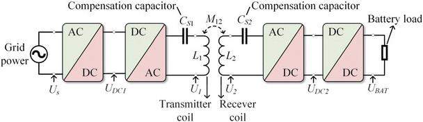
Figure 1: WPT system schematic.
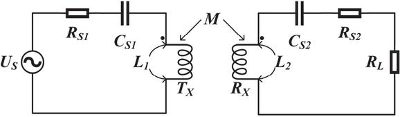
Figure 2: S-S compensation circuit.
The density of eddy currents generated by the induced electromotive force is:
| (4) |
where represents the electric potential, A is magnetic vector, is material conductivity, is relative permeability of the material, is dielectric constant, and j is an imaginary unit. The eddy currents generated in the shielding mechanism can be expressed by the volume fraction:
| (5) |
From equation (5) it can be seen that eddy currents are affected by the system operating angular frequency , the conductivity and dielectric constant of the shielding material. However, electrical materials also have drawbacks, such as affecting the magnetic field state around the receiving coil, and eddy currents generate heat, which not only increases transmission losses but also causes safety hazards. Therefore, the current WPT shielding structure is usually a combination of electrical and magnetic materials, which reduces energy loss and improves system efficiency to have better shielding performance.
The location, shape and size of the shielding material can be varied during design to suit the actual application. Because magnetic field lines naturally form closed loops and cannot be directly blocked, we can design specialized magnetic conduction pathways to keep the magnetic field primarily circulating within the equipment. This significantly reduces magnetic field leakage to the outside, achieving effective shielding. There is a relationship in the magnetic field:
| (6) |
where is magnetic flux, is the magnetomotive force, which is determined by the product of the number of turns of the coil and the current, and is the magnetoresistance, which represents the hindering effect of the magnetic circuit on the magnetic flux. Analysis of the relationship between the quantities in equation (6) shows that magnetic flux mainly passes through the shielding material with low reluctance and high relative permeability, which reduces magnetic leakage into the air. In constructing the magnetic field shielding mechanism, the low magnetoresistance path is shown in Fig. 3.
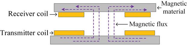
Figure 3: Magnetic flux path.
In the design of the magnetic shielding mechanism, in addition to considering the shielding effect, it is also necessary to synthesize the requirements of the use of the environment to make changes to the shape and weight of the shielding mechanism. The WPT system in this paper operates at 85 kHz, mainly utilizing a high relative permeability shield to shunt the magnetic flux and improve coupling between the transceiver coils. It can be seen that magnetic induction intensity inside the high relative permeability shield is much larger than that outside, while the magnetic lines of force in the low relative permeability material are almost perpendicular to the high relative permeability material. In this way most of the low-frequency magnetic field energy is constrained to pass inside the shield, thus providing shielding.
III. ROBUST OPTIMIZATION BASED ON K-TRANS SURROGATE MODEL
The core of solving robust optimization problems is to take offset uncertainty into account in the optimal design in order to attenuate the effect of offset uncertainty. Existing methods usually require a large number of samples and are usually handled in a probability-driven manner, which may lead to an increase in computational time cost with large errors in the results. Considering the complexity and high simulation cost of WPT systems, this paper adopts the K-Trans based method to realize the embedding of the effect of offset uncertainty among coupled mechanisms of WPT systems to achieve robust optimization.
A. K-Trans surrogate model
Transformer is able to react more sensitively to changes in the dataset due to the remote dependency of its multi-head self-attention mechanism, providing better adaptability for regression tasks [23, 24]. The traditional Transformer has a multi-layer perceptron (MLP) layer after the self-attention layer. In MLP, the neuron connections are usually a real value representing the weights, and the neuron itself is equipped with a nonlinear activation function, usually a sigmoid function. The computation process of MLP is to first weight the inputs of the weights weighting and then introducing nonlinearity through the activation function. KAN is realized based on the Kolmogorov-Arnold (K-A) representation theorem, which shows that any continuous function can be represented as a nested combination of finitely many univariate functions:
| (7) |
where and are univariate functions. KAN utilizes the K-A representation theorem to represent the weight parameters as a kind of B-spline. The B-spline function connects the two neurons directly and is essentially a segmented polynomial function that achieves a high degree of smoothing where the polynomial blocks intersect. The K-A theorem states a high-dimensional function through equation (7), which can be reduced to learning one-dimensional functions of polynomial order. These one-dimensional functions are not always smooth functions that are easy to learn, and thus high-dimensional decomposition is achieved by parameterizing each one-dimensional function as a B-spline function [24]. In Transformer, by replacing the MLP with KAN, we can take advantage of the better interpretability of KAN to achieve self-learning of the activation function while moving the activation function to the “edge”, so as to realize the smooth processing of the data, which not only learns the features, but also optimizes these learned features with high accuracy, thus obtaining a smooth function that approximates the data. This not only ensures the accurate approximation ability of high-dimensional functions but also decomposes the multi-dimensional function into a univariate function combination to simplify computational complexity. The improved model structure is shown in Fig. 4.
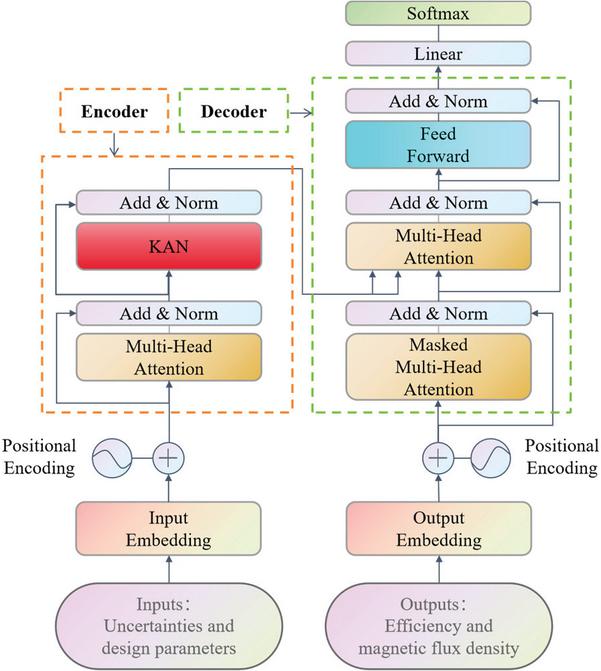
Figure 4: K-Trans model.
As can be seen from Fig. 4, the K-Trans model consists of four parts: model input, encoder, decoder and model output. The model input data integrates the offset uncertainty of the WPT system with the design parameters of the shielding structure, and the maximum value of the magnetic field strength and the system transmission efficiency at the four fixed observation points around the WPT system are used as the model outputs to realize the construction of the surrogate model under the uncertainty scenario.
Through the training of the above model, the LMF and energy transfer efficiency surrogate model of the WPT system containing the effect of the offset uncertainty between the coupling mechanisms of the WPT system is obtained. By calling the surrogate model through the MC method, the corresponding outputs are obtained, which are used to assist the optimization. Based on these samples, simulation can be replaced thus saving the time cost of the optimization process. The accuracy of the surrogate model in this paper is verified by comparing it with the MC method.
B. Optimization design method
Based on the above K-Trans uncertainty surrogate model, we quantify the effect of uncertainty surrogate into the optimization design process, and in the optimization stage we only consider the optimization of the design parameters, while the offset uncertainty is embedded into the optimization process, which is regarded as the optimization background factor, so as to achieve robust optimization. To address the above problems, this paper adopts an intelligent optimization algorithm for computation. MOEDO is a heuristic method [25] that utilizes the theory of exponential distribution combined with the idea of dynamic optimization. It integrates an information feedback mechanism (IFM) and transforms a multi-objective task into a single-objective sub-task, thereby overcoming the local optimum. The pseudo-code of the MOEDO algorithm is shown in Algorithm 1.
In the embedding operation of offset uncertainty, the design variables are always the same in both the robust optimization process and the traditional deterministic optimization process, the offset uncertainty variables are only used as stochastic inputs to the model, and the Pareto frontier searched by MOEDO is always for the optimization results with the design factors as variables. The optimization in the deterministic case and the robust optimization of the WPT system considering the effect of offset uncertainty can be achieved by the aforementioned MOEDO optimization method combined with the K-Trans surrogate model proposed in Appendix A.
IV. OPTIMIZED DESIGN OF SHIELDING STRUCTURE
A. Structural design
In the design of shielding structure, this paper adds ultra-thin single-layer nanocrystalline material with high relative permeability to realize the composite shielding structure based on the combination of aluminum plate and ferrite unit. The nanocrystalline material used in this study exhibits a relative permeability of 22,000 at room temperature and 85 kHz, whereas the ferrite component shows only 3300 under identical conditions. In the shielding design, inner peripheral nanocrystalline strips guide magnetic leakage from the coil center into coupling paths, while outer strips redirect leakage from non-operating regions back to active areas. Where the ferrite unit is used to compensate for the nanocrystalline material shielding loophole, and finally the aluminum plate is utilized for electrical shielding, and the three materials are placed in layers, as shownin Fig. 5.
Compared with the traditional shielding structure covered by a large area of ferrite, the use of nanocrystalline to replace part of the ferrite can achieve Compared with the traditional shielding structure covered by a large area of ferrite, the use of nanocrystalline to replace part of the ferrite can achieve the effect of reducing the overall weight of the WPT system, saving the space occupied by the shielding structure and improving the robustness of the overall structure. However, since the ferrite compensation unit in this paper is not symmetrically placed, the magnetic field distribution around the system is not symmetrical. In addition, the offset uncertainty between the coupling mechanisms also affects the overall shielding effect. Therefore, it is necessary to design the most suitable combination of shielding materials and placement form to ensure the best performance of the whole WPT system under the influence of offsetuncertainty.

The WPT system in this paper consists of a transmitting coil Tx, a receiving coil Rx, two end-to-end shields and a converter circuit. The dimensions of both Tx and Rx are 200 200 cm, and the cross-sectional area of the coils is 1.3 10-5 mm2. Both coils are composed of 15 turns coil, and the coil wires are made of metallic copper wrapped with an insulating layer on the outside. When Tx and Rx are aligned and the spacing between the coils is 5 cm, the system operates under ideal conditions, and the system input power of the WPT is 300 W with an operating frequency of 85 kHz. the distribution of the magnetic flux density B around the WPT before and after the addition of the shielding structure is shown in Fig. 6. Group 1 represents no shielding, Group 2 represents aluminum plate and ferrite combination shielding, and Group 3 represents aluminum plate, ferrite and nanocrystalline combination shielding before optimization. As shown in Fig. 6, during normal operation of the WPT system, the magnetic field distribution in the cross-sectional plane exhibits an outward dispersion pattern, with higher magnetic flux density concentrated at the coil center. After implementing the shielding structure, the magnetic field is effectively confined to the operating region, while the leakage fields on the upper and lower surfaces of the WPT system are significantly attenuated, thereby enhancing operational safety.
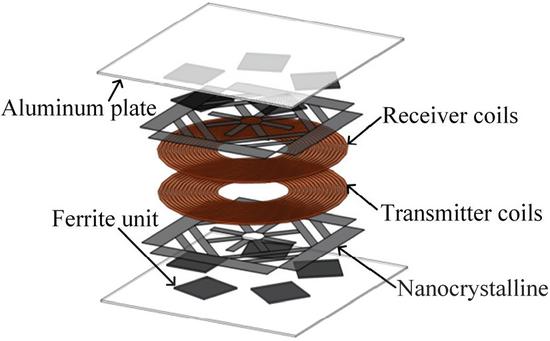
Figure 5: WPT system combined shield structure.
The shielding structure design parameters and offset uncertainty tolerance range of the model in this paper are shown in Tables 1 and 2. Among them, the aluminum plate and the ferrite unit play a role in compensating the nanocrystalline shielding layer, so the material parameters and placement of the two are crucial. Therefore, the thickness of the ferrite unit , the distance of the ferrite unit from the center of the WPT system , the relative angle of the upper and lower ferrite layers, and the thickness of the aluminum plate are taken as the optimization variables in this paper, so as to achieve the best matching effect with the nanocrystalline shielding layer. Since the offset between the coils of the WPT system is equiprobable in all directions, it is usually regarded as a uniform distribution in engineering applications, and U denotes a uniformdistribution.
Currently, the most widely used electromagnetic exposure standard for WPT systems is the ICNIRP 2010 guideline, which divides different limit values for different WPT frequency ranges. The ICNIRP 2010 clearly states that, in order to ensure that the human body is not subjected to neurostimulation, in the frequency range of 3 kHz–10 MHz, the limit of the public’s exposure to the time-varying magnetic field is 27 T. The WPT system developed in this study operates at 85 kHz, with electromagnetic exposure compliance based on the ICNIRP 2010 occupational reference level of 27 T for magnetic flux density. Since the magnetic flux density is higher at the vertical center located between the coils, this paper establishes four fixed observation points , and in four directions in the middle of the vertical direction between the coupling mechanism, 20 cm from the center of the coils, for evaluating the shielding effect, as shown in Fig. 7.
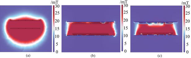
Figure 6: Magnetic flux density distribution. (a) Group 1, (b) Group 2, (c) Group 3.
Table 1: Design variables and distribution parameters
| Design Variables | Distribution Parameters | Unit |
| t1 | U [0,0.04] | m |
| d | U [0.002,0.004] | m |
| t2 | U [0.001,0.003] | m |
| U [0,72] | ∘ |
Table 2: Uncertainty factors and distribution parameters
| Uncertainty | Distribution | |
| Factors | Parameters | Unit |
| Horizontal offset | U [-0.05,0.05] | m |
| Vertical offset | U [-0.05,0.05] | m |
| Coil distance | U [0.04,0.06] | m |
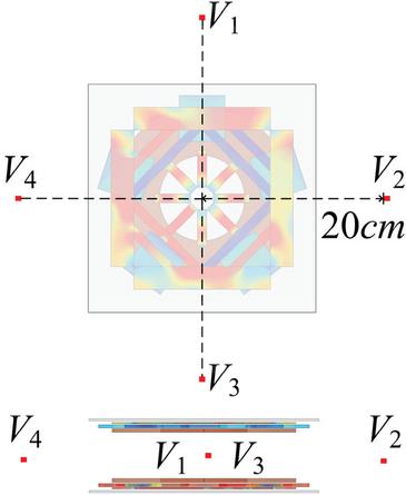
Figure 7: Observation point.
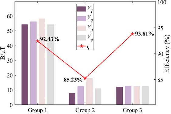
Figure 8: Observation point indicators.
B. Shielding performance
The magnetic field strength distribution and the energy transfer efficiency of the WPT system at the four observation points with and without the shielding mechanism are shown in Fig. 8 and Table 3. Before and after adding Group 2 shielding to the WPT system in this paper, the maximum reduction of the B value at the four observation points reaches 85.19% but, at the same time, the system efficiency decreases by 7.2%, which is due to the fact that after adding the shielding layer, although the ambient leakage magnetic field becomes less, a part of the electrical energy is converted into thermal energy due to the eddy current effect of the aluminum plate, thus leading to a reduction of efficiency. The maximum value of the magnetic field strength at the four observation points is noted as , which will be used as an indicator of the shielding effect of in this paper because the shielding structure is asymmetric.
After adding the nanocrystalline shielding layer, compared with the form of Group 2 combination, the energy transfer efficiency of the WPT system is improved by 8.58% while is reduced by 30.05%, which shows that the nanocrystalline material is able to improve the degree of system coupling due to its high relative permeability, resulting in the efficiency of the WPT system being elevated. In the optimization process of shielding structure design, what we need to find is the optimal thickness of the aluminum plate and ferrite unit as well as the optimal placement of the ferrite compensation unit, so as to achieve the optimal way of combining with nanocrystalline.
Considering the practical applications of the WPT system, according to the uncertainty factors and their distributions in Table 3, a random sampling method is used to sample and calculate the probability distribution function (PDF) of the energy efficiency of the original system and the maximum value of the magnetic field strength at a fixed observation point. In order to validate the Transformer surrogate model before and after the improvement, the results are compared with the pre-improvement Transformer and MC calculations. Considering the cost of simulation computation, the MC method with 10,000 simulations can provide enough accuracy to meet the needs of most engineering problems. Comparison results are shown in Fig. 9. As can be seen from Fig. 9, the computational results of the K-Trans are basically consistent with those of the MC, and the computational accuracy is slightly improved over the MC and the Transformer. Under the presence of uncertainty, the mean value of the WPT system efficiency predicted by the surrogate model is 78.83%, and the mean value of the magnetic field strength is 22.64 T. As shown in Fig. 9 (a), the original structure of the WPT is subject to the possibility of transgressing the limit under the influence of the offset uncertainty, with a probability of 27.34%, and therefore the shielding structure needs to be optimized so as to reduce the transgressing probability.
Table 3: Observation point value
| Group 1 | Group 2 | Group 3 | |
| /T | 54.42 | 8.06 | 12.17 |
| /T | 56.26 | 12.53 | 12.68 |
| /T | 58.27 | 18.07 | 12.64 |
| /T | 54.39 | 11.02 | 12.61 |
| MC | Transformer | K-Tran | |
| Time/min | 22833 | 2290 | 2062 |
in addition, in terms of computation time, the time required to calculate the WPT system operation for a single scenario using the multi-physics field simulation software is 2 minutes and 17 seconds, and the computation time for the three methods in this paper for a single structure is shown in Table 4. It shows that under the condition of calculating the same WPT system structure, the calculation cost of 10,000 times MC method is very high, while the calculation time cost of K-Trans saves 90.97% compared to the MC method. Thus, the K-Trans method can ensure the realization of improved computational efficiency while guaranteeing accurate calculation results.
In the optimization process, determining the optimum does not consider other factors and is calculated directly through optimization. While robust optimization needs to consider the offset uncertainty among the coupled mechanisms of the WPT system, in this paper, the uncertainty effect is embedded into the optimization as a data background to realize robust optimization. For the WPT system, the of the observation point is optimal while the system works efficiently. The design variables corresponding to the target points in the Parato solution set are shown in Table 5.
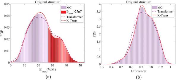
Figure 9: PDF (a) and (b) .
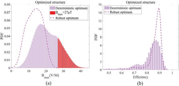
Figure 10: Comparison of PDF of deterministic optimum and robust optimum (a) and (b) .
Table 5: Optimal design variables
| t1/m | d/m | t2/m | /m | |
| Deterministic optimum | 0.003 | 0.032 | 0.0019 | 7 |
| Robust optimum | 0.004 | 0.025 | 0.0028 | 35 |
in order to verify the improvement effect of the energy transfer efficiency and shielding performance of the WPT system under the influence of offset uncertainty, according to the parameter settings in Table 2 and the optimized parameters in Table 5, the probability distribution curves of and are calculated using the agent model and compared with the pre-optimization PDF, as shown in Fig. 10 and Table 6.
Table 6: Statistical parameter
| Original | Deterministic | Robust | |
| Structure | Optimum | Optimum | |
| Mean of /% | 78.83 | 80.73 | 86.60 |
| Mean of Bmax/T | 22.64 | 20.63 | 13.42 |
| Transgression probability P/% | 27.34 | 19.09 | 0 |
Results demonstrate that the robustly optimized system achieves a mean efficiency of 86.60% with an associated magnetic field strength of 13.42 T. In contrast, the deterministically optimized structure shows significantly degraded performance, with mean efficiency dropping to 80.73% and magnetic field strength increasing to 20.63 T. In addition, analyzing from the perspective of the transgressing probability, the transgressing probability of the deterministically optimal structure reaches 19.09%, whereas the robustly optimized structure demonstrates an overshoot probability of 0. The transgression probability of magnetic leakage of the WPT system is reduced to 0, and there is no possibility of transgression, which ensures the safety of electromagnetic exposure of the users. Therefore, the robust-optimized WPT system’s offset resistance is improved, and the RDO method assisted by the K-Trans surrogate model can effectively cut down the negative impact caused by the offset uncertainty of the WPT system, and improve the stability of the system’s electromagnetic shielding, transmission efficiency and safety of the users.
V. EXPERIMENTAL RESULTS
In order to validate the RDO method proposed in this paper, a 300 W, 85 kHz system is constructed to verify the effectiveness of the proposed method, and the system is shown in Figs. 11 and 12. The system consists of a coil, converter circuit, shield and resistive load. In this paper, the coil spacing adjustment is realized using acrylic pads that do not have any effect on the electromagnetic field. In the experiment, the measurement device of magnetic field strength is based on the ELT-400 series probes used for safety assessment of human exposure to magnetic fields under the German company Narda, which meets the measurement standards of ICNIRP 2010.
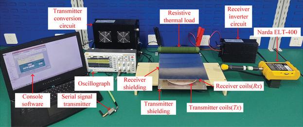
Figure 11: Set up.
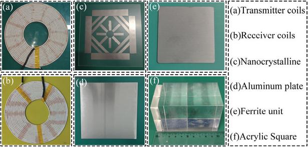
Figure 12: Enlarged view.
From the simulation results in section IV., it can be seen that the shielding effect of deterministic optimal structure in the deterministic case is superior to that of the robust optimal value, which is verified in the following based on the experimental build. In the process of verifying the effect of robust optimal shielding structure, in this experiment, the step of the three uncertainty factors , and are all set to 1 cm, the numerical planes of with different coil spacing are used as a differentiation, and the data of corresponding to the efficiency and the magnetic field strength under the case of with different coil spacing are obtained to chart the four-dimensional response surface plots to verify the two kinds of structures under the influence of the uncertainty factors’ shielding performance. From the distribution parameters of the uncertainty factors in Table 2, it can be seen that there are 363 possible combinations of the three uncertainty factors for each shielding structure in the experimental process at a step of 1 cm, and the response surface plots are realized at the resulting 363 points.
As shown in Figs. 13 and 14, the 3D response surface plots reveal significant differences between the robustly optimized structure and deterministic structure under asymmetric shielding conditions. The three coordinate axes represent positional offsets, with dual color scales indicating maximum magnetic flux density and transfer efficiency . Key findings include: at cm, the system achieves optimal performance balance, with the robust structure demonstrating 86.6% efficiency (4.95% improvement over deterministic design) and 13.4 T (5.17 T reduction). This enhancement stems from adaptive coupling spacing adjustment in the robust framework, which simultaneously improves magnetic coupling efficiency through reduced coil separation and confines magnetic fields within operational zones. Under misalignment conditions, the robust design reduces leakage by 34% while lowering exceedance probability from 12.3% to 0%, fully complying with ICNIRP 2010 27 T safety limit. Statistical data in Table 7 confirm that, under various uncertainty factors, the robust optimization framework not only improves average efficiency by 4.95% but also ensures zero magnetic exceedance, providing an effective solution for handling positional offsets in practical deployments.
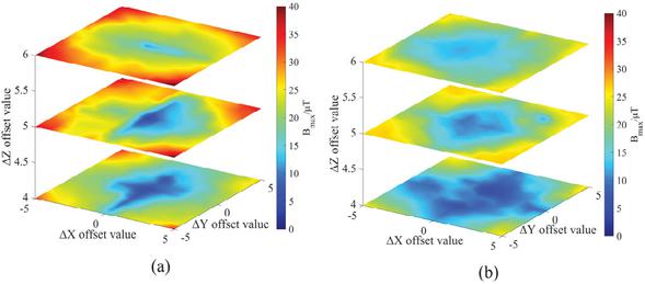
Figure 13: Response surface plot (a) deterministic optimum and (b) robust optimum.
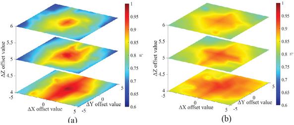
Figure 14: Response surface plot (a) deterministic optimum and (b) robust optimum.
Table 7: Statistical parameter
| Deterministic | Robust | |
| Optimum | Optimum | |
| Mean of /% | 79.84 | 84.79 |
| Mean of Bmax/T | 23.22 | 18.05 |
| Transgression probability P/% | 27.55 | 0 |
Experimental validation confirms that the robustly optimized structure significantly enhances both the offset resistance and shielding performance of the WPT system. Leveraging the K-Trans surrogate model, our methodology quantifies positional uncertainty impacts by constructing shielding performance surrogate models and deriving statistical parameters, while simultaneously enabling multi-objective robust optimization through MOEDO to improve shielding effectiveness and positional tolerance.
Comparative analysis reveals that, under positional uncertainty conditions, the K-Trans framework accurately captures shielding behavior patterns, and MOEDO achieves Pareto-optimal designs with 15.7% higher shielding efficiency and 42.3% greater positional tolerance compared to deterministic methods.
VI. CONCLUSION
The objective of this paper is to design highly offset-tolerant WPT shielding structures to counteract the negative effects of the offset uncertainty existing between the coupled mechanisms of the system and to improve the electromagnetic safety of the system. This paper proposes a robust optimization method based on the combination of K-Trans surrogate model and MOEDO. Its computational accuracy is basically the same as that of the MC method, and it noticeably saves the computational cost. From experimental results, K-Trans computational time cost is reduced by 90.97% compared with the MC method. The mean value of system efficiency with robust optimal structure is improved by 4.95% compared with the deterministic optimal structure, which effectively improves energy transfer efficiency. Mean of is reduced by 5.17 T, and the probability of system overrun is reduced to 0, which effectively protects the user’s electromagnetic exposure safety. Therefore, the scheme proposed in this paper can provide an efficient and feasible solution for an optimized design of the shielding structure of WPT systems. Considering that the variables involved in practical applications are more complex, in future research we will look for more suitable methods for high-dimensional calculations to improve the safety and stability of WPT systems.
ACKNOWLEDGMENT
This work was supported in part by the Jilin Province and Changchun City Major Science and Technology Special Project 2024 Annual FAW Independent Innovation (Key Core Technology Research and Development) Major Science and Technology Special Project under Grant 20240301017ZD.
REFERENCES
[1] R. Jegadeesan, S. Nag, K. Agarwal, N. V. Thakor, and Y.-X. Guo, “Enabling wireless powering and telemetry for peripheral nerve implants,” IEEE J. Biomed. Health. Inform., vol. 19, no. 3, pp. 958–970, May 2015.
[2] G. D. Ntouni, A. S. Lioumpas, and K. S. Nikita, “Reliable and energy-efficient communications for wireless biomedical implant systems,” IEEE J. Biomed. Health. Inform., vol. 18, no. 6, pp. 1848–1856, Nov. 2014.
[3] S. Hong, Y. Kim, S. Lee, S. Jeong, B. Sim, H. Kim, J. Song, S. Ahn, and J. Kim, “A frequency-selective EMI reduction method for tightly coupled wireless power transfer systems using resonant frequency control of a shielding coil in smartphone application,” IEEE Trans. Electromagn. Compat., vol. 61, no. 6, pp. 2031–2039, Dec. 2019.
[4] L. Chaoqun, W. Xiaokang, W. Bin, and G. Yan, “Research on influence of the electric vehicle on life safety during the wireless charging process,” in 2018 IEEE 2nd International Electrical and Energy Conference (CIEEC), Beijing, China, pp. 507–512, Nov. 2018.
[5] L. Fang, H. Zhou, W. Hu, X. Gao, H. Liu, and Q. Deng, “Design and analysis of flexible capacitive power transfer with stable output capability,” IEEE Transactions on Circuits and Systems. I: Regular Papers, vol. 69, no. 11, pp. 4691–4701, Nov. 2022.
[6] D. Patil, M. K. McDonough, J. M. Miller, B. Fahimi, and P. T. Balsara, “Wireless power transfer for vehicular applications: Overview and challenges,” IEEE Trans. Transp. Electrif., vol. 4, no. 1, pp. 3–37, Mar. 2018.
[7] X. Shang, L. Xu, Q. Yu, L. Bo, G. Lv, Y. Chi, and T. Wang, “Uncertainty quantification and optimal design of EV-WPT system efficiency based on adaptive gaussian process regression,” Applied Computational Electromagnetics Society (ACES) Journal, vol. 38, no. 12, pp. 929–940, Dec. 2023.
[8] T. Tan, T. Jiang, Y. Wu, Y. Zhu, and Y. Chi, “Safety assessment of gender-specific human electromagnetic exposure with aortic valve stents for EV-WPT,” Applied Computational Electromagnetics Society (ACES) Journal, vol. 39, no. 08, pp. 742–753, Aug. 2024.
[9] International Commission on Non-Ionizing Radiation Protection, “Guidelines for limiting exposure to electromagnetic fields (1 Hz to 100kHz),” Health Phys., vol. 118, no. 5, pp. 818–836, 2020.
[10] International Commission on Non-Ionizing Radiation Protection, “ICNIRP Guidelines for Limiting Exposure to Time-Varying Electric, Magnetic and Electromagnetic Fields (100 kHz to 300 GHz),” Health Phys., vol. 128, no. 2, pp. 190–202, 2024.
[11] W. H. Bailey, R. Bodemann, J. Bushberg, C. K. Chou, R. Cleveland, A. Faraone, K. R. Foster, K. E. Gettman, K. Graf, T. Harrington, A. Hirata, R. R. Kavet, J. Keshvari, B. J. Klauenberg, A. Legros, D. P. Maxson, J. M. Osepchuk, J. P. Reilly, R. R. A. Tell, A. Thansandote, K. Yamazaki, M. C. Ziskin, and P. M. Zollman, “Synopsis of IEEE Std C95.1TM-2019 IEEE Standard for Safety Levels With Respect to Human Exposure to Electric, Magnetic, and Electromagnetic Fields, 0 Hz to 300 GHz,” IEEE Access, vol. 7, pp. 171346–171356, 2019.
[12] C. Lu, X. Huang, X. Liu, Y. Zeng, R. Liu, C. Rong, and M. Liu, “Design and optimization of the low-frequency metasurface shield for wireless power transfer system,” IEEE Trans. Transp. Electrif., vol. 8, no. 1, pp. 723–733, Mar. 2022.
[13] Q. Zhu, Y. Zhang, Y. Guo, C. Liao, L. Wang, and L. Wang, “Null-coupled electromagnetic field canceling coil for wireless power transfer system,” IEEE Trans. Transp. Electrif., vol. 3, no. 2, pp. 464–473, June 2017.
[14] Q. Zhu, Y. Guo, L. Wang, C. Liao, and F. Li, “Improving the misalignment tolerance of wireless charging system by optimizing the compensate capacitor,” IEEE Trans. Ind. Electron., vol. 62, no. 8, pp. 4832–4836, Aug. 2015.
[15] R. Qin, J. Li, J. Sun, and D. Costinett, “Shielding design for high-frequency wireless power transfer system for EV charging with self-resonant coils,” IEEE Trans. Power Electron., vol. 38, no. 6, pp. 7900–7909, June 2023.
[16] N. Fu, J. Deng, Z. Wang, and D. Chen, “Dual-phase-shift control strategy with switch-controlled capacitor for overall efficiency optimization in wireless power transfer system,” IEEE Trans. Veh. Technol., vol. 72, no. 6, pp. 7304–7317, June 2023.
[17] Z. Li, C. Zhu, J. Jiang, K. Song, and G. Wei, “A 3kW wireless power transfer system for sightseeing car supercapacitor charge,” IEEE Trans. Power Electron., vol. 32, no. 5, pp. 3301–3316, May 2017.
[18] D. E. Gaona, C. Jiang, and T. Long, “Highly efficient 11.1-kW wireless power transfer utilizing nanocrystalline ribbon cores,” IEEE Trans. Power Electron., vol. 36, no. 9, pp. 9955–9969, Sep. 2021.
[19] P. Lagouanelle, F. Freschi, L. Pichon, and L. Giaccone, “Fast and reliable human exposure assessment around high power systems using surrogate modeling,” IEEE Access, vol. 12, pp. 34835–34845, 2024.
[20] Y. Wang, F. Wang, Y. Tian, A. Sun, and B. Liu, “Surrogate-assisted multiobjective optimization of double-D coil for inductive power transfer system with LCC-LCC compensation network,” IEEE Trans. Ind. Electron., vol. 71, no. 9, pp. 10612–10624, Sep. 2024.
[21] X. Li, J. Li, L. Zuo, L. Zhu, and H. T. Shen, “Domain adaptive remaining useful life prediction with Transformer,” IEEE Trans. Instrum. Meas., vol. 71, pp. 1–13, 2022.
[22] B. Zhang, H. Yuan, J. Ge, L. Cheng, X. Li, and C. Xiao, “Weak appearance aware pipeline leak detection based on CNN-Transformer hybrid architecture,” IEEE Trans. Instrum. Meas., vol. 74, pp. 1–9, 2025.
[23] A. Feng, X. Zhang, and X. Song, “Unrestricted attention may not be all you need masked attention mechanism focuses better on relevant parts in aspect-based sentiment analysis,” IEEE Access, vol. 10, pp. 8518–8528, 2022.
[24] Y. Dash, S. C. Sarangi, V. Gupta, N. Kumar, and A. Abraham, “A novel context-aware feature pyramid networks with Kolmogorov-Arnold modeling and XAI framework for robust lung cancer detection,” IEEE Access, vol. 13, pp. 108992–109008, 2025.
[25] K. Kalita, J. V. N. Ramesh, L. Cepova, S. B. Pandya, P. Jangir, and L. Abualigah, “Multi-objective exponential distribution optimizer (MOEDO): A novel math-inspired multi-objective algorithm for global optimization and real-world engineering design problems,” Sci. Rep., vol. 14, no. 1, p. 1816, 2024.
BIOGRAPHIES

T. H. Wang received the B.S. degree in electrical engineering and the Ph.D. degree in vehicle engineering from Jilin University, Changchun, Jilin, China, in 2010 and 2016, respectively. From 2016 to 2019, he was a Post-Doctoral Researcher at the Department of Science and Technology of Instrument, Jilin University, where he is currently an Associate Professor with the College of Instrumentation and Electrical Engineering. His research interests include the uncertainty quantification of wireless power transfer of EVs and human electromagnetic exposure safety.

K. F. Zhao received the B.S. degree in electrical engineering and automation from the College of Instrumentation and Electrical Engineering, Jilin University, Changchun, Jilin, China, in 2023, where he is currently pursuing the M.S. degree in electrical engineering. His research interests include human electromagnetic safety protection and electromagnetic compatibility of EVs.

H. W. Duan received the B.S. degree in electrical engineering and automation from the College of Electrical Engineering, Northeast Electric Power University, Jilin, China, in 2024. He’s currently working on his M.S. degree at Jilin University, Jilin. Since 2024, he has worked on the operation and the application of micro-grid systems.

G. Lv received the master’s degree in electronic circuit and system from College of Electronic Science & Engineering, Jilin University, Changchun, Jilin, China, in 2008. He joined the National Automotive Quality Supervision & Inspection Center (Changchun) after graduation. He is currently head of the EMC department. He is in charge of EMC performance in vehicle approval under the direction of the Ministry of Industry and Information Technology (MIIT) and Certification and Accreditation Administration of the P.R.C. He focuses on test methods improving and National Standards edit and amendment in EMC domain. He has joined teams responsible for EMC part of “Test and evaluation of autonomous electric vehicle” subject which is released by Ministry of Science and Technology (MOST) and “Research on real-time concurrent simulation test technology of multi-source sensor information of intelligent networked vehicle” which is released by Science and Technology Department of Jilin Province.

Q. Y. Yu received the B.S. and the M.S. degrees from the College of Communication Engineering, Jilin University, Changchun, Jilin, China, in 2016 and 2020, respectively, where he is pursuing the Ph.D. degree. His research interests include uncertainty quantification and electromagnetic compatibility of EVs.

S. S. Guan received the B.S. degree in precision instruments and machinery and the Ph.D. degree in measurement technology and instruments from Jilin University, Changchun, Jilin, China, in 2008 and 2012, respectively. In 2019, she was a Visiting Scholar at the Southern University of Science and Technology, Shenzhen. She is currently an Associate Professor with the College of Instrumentation and Electrical Engineering, Jilin University. Her research interests include forward modeling and inverse algorithms of EM fields, and the development of electromagnetic instruments.
ACES JOURNAL, Vol. 40, No. 11, 1090–1101
DOI: 10.13052/2025.ACES.J.401105
© 2025 River Publishers