Ultra-Wideband Frequency Selective Surface With Metal Gratings for Polarization Conversion Under Arbitrary Polarized Angles
Xueyan Song, Hua Lu, Shaochen Yang, XuPing Li, Chao Xiong, YunQi Zhang, and Xin Wang
School of Electronic Engineering Xi’an University of Posts & Telecommunications, Xi’an 710121, China
xysong6597@126.com, 1690998220@qq.com, 1625804505@qq.com, lixuping@163.com, 2096712375@qq.com, johnny_5@126.com, wang.xin@xupt.edu.cn
Submitted On: June 20, 2025 Accepted On: October 07, 2025
Abstract
A frequency selective surface (FSS) with metal gratings (FSSMGs) is proposed for insensitive cross polarization conversion in an ultra-wide bandwidth. To obtain the ultra-wide bandwidth, a multiple-resonance structure of metal gratings are selected as the sub-units. The unit of FSSMGs is composed of four grating-via-grating (GVG) modules. Each GVG module is made up of two layers of vertically arranged metal grids, quasi-wave-guiding structures (metalized vias), and shielded floors. To ensure the FSSMGs convert waves in arbitrary polarization directions, the four GVG modules in the unit are rotationally symmetric arranged. Simulated results show that the cross-polarization transmission coefficient is greater than 1 dB in an ultra-wide band of 8.17–18.5 GHz (77.5%), in which the PCR (polarization conversion ratio) and the ECR (energy conversion ratio) are greater than 90%. Meanwhile, the designed FSSMGs is insensitive for arbitrary polarized angles. In addition, the proposed FSSMGs can operate in the band 8.17–12 GHz (38.0%) and 15–18.5 GHz (20.9%) when the incident angle is less than 45∘. To verify the simulated results, the proposed FSSMGs was fabricated and measured, and the measured results are in good agreement with the simulated ones.
Keywords: Grating-via-grating (GVG) module, incidence stability, polarization converter, polarization insensitivity, ultra-wideband..
1 INTRODUCTION
A frequency selective surface (FSS) is a type of spatially selective filter composed of a periodic array of metallic resonant elements arranged in a two-dimensional plane. It exhibits a transmission/reflection response that is highly dependent on the frequency of the incident electromagnetic wave, thereby enabling the spatial filtering of electromagnetic radiation [1, 2]. Polarization converters, a type of FSS, have been found important applications in reducing radar cross-sections [3], wireless communication [4], chiral sensing [5], among other fields. In practical applications, the polarization converter is typically placed between transmitter and receiver antennas to facilitate polarization conversion. In general, polarization converters can be categorized into transmission type [3, 4, 6, 7, 8, 9, 10] and reflection type [11, 12, 13] according to their transmission mode. They can also be classified into line-to-line polarization conversion [6, 7, 8, 9, 10, 11, 12, 13], line-to-circular polarization conversion [14, 15], and circular-to-circular polarization conversion [16] in accordance with their polarizing category. Polarization converters have been researched for over a decade. Heretofore, extensive studies have been conducted on performances of polarization converters such as low profile [17], multi-functionality [18], wide bandwidth [19], oblique incidence stability [12], and reconfigurability [20]. However, the majority of traditional polarization converters can merely receive waves in a single polarization direction [6, 7, 8, 9, 10, 11, 12, 13], which restricts their applications.
In recent years, a new type of polarization-insensitive cross polarization converter (PICPC) has been designed. Unlike traditional polarization converters, PICPCs can receive arbitrary polarized waves and convert them into cross-polarized waves, which have strong angle stability [8, 9, 10]. In [8], an insensitive polarization converter was proposed. The unit of the polarization converter consists of four monopole-via-monopole (MVM) modules, which can receive waves in four polarization directions and it exhibits a 3.0-dB transmission bandwidth ranging from 5.5 to 6.18 GHz (12%). In [10], a bi-isotropic Huygens’ metasurface (BIHMS) is proposed for polarization-insensitive cross-polarization conversion in the bandwidth from 8.4 to 11.2 GHz (27.7%). Though there have been numerous papers on PICPCs, bandwidth limits their potential applications. To obtain ultra-wide bandwidth, several novel converters [21, 22, 23] according to the theory of multiple resonances have been presented. In [21], an ultra-wideband tri-layer transmissive linear polarization converter is designed for terahertz waves. It achieves a conversion efficiency of more than 80% in the band from 0.2 to 1.0 THz (133%). In 2023, a polarization converter with collective coupling was proposed in [13]. The converter consists of two layers of strip-shaped grids and serrated grids, which can convert linearly polarized waves into cross-polarized ones in an ultra-wide band, and the conversion efficiency is above 80%. How to achieve an ultra-wide bandwidth with a conversion efficiency of more than 90% is still a challenge.
To obtain a conversion efficiency of over 90% in an ultra-wide bandwidth for arbitrary polarization angles, an FSSMGs is proposed in this paper. The unit of proposed FSSMGs consists of four grating-via-grating (GVG) modules, with a size of 0.16 (8.25 GHz) and a section thickness of 0.13. The four GVG modules are placed vertically in such a way that the proposed FSSMGs can achieve polarization insensitivity and incidence stability. Simulations show that the proposed converter is capable of transforming linearly polarized waves into cross-polarized waves (90∘ polarization rotation) in the band from 8.17 GHz to 18.5 GHz (77.5%), in which the polarization conversion ratio (PCR) is above 90% on average. The presented FSSMGs is polarization-insensitive under arbitrary polarized angles. In addition, the proposed FSSMGs can obtain oblique incidence stability in the band 8.17–12 GHz (38.0%) and 15–18.5 GHz (20.9%) when the incident angle is less than 45∘.
2 DESIGN PROCESS AND OPERATION PRINCIPLE
2.1 Design process
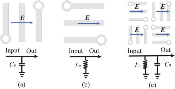
Figure 1 Grid structures in different directions and their equivalent circuit models.
To achieve the required frequency band, gratings are selected as the sub-units of FSSMGs, and the corresponding equivalent resonance circuit can be manifested as depicted in Fig. 1. When perpendicular to the electric field direction, gratings behave as capacitance () [23], and thus the structure possesses low-pass filtering characteristics in Fig. 1 (a). When parallel to the electric field direction, gratings behave as inductance () and thus the structure exhibits high-pass filtering characteristics [24] as shown in Fig. 1 (b). Therefore, to obtain a band-pass response, the unit of FSSMGs are designed as in Fig. 1 (c), which consists of gratings in two vertical directions, and the grids behave as a parallel resonance circuit of inductance and capacitance.
Bandwidth depends mainly on the number of metals in each grating. Gratings made up of 3, 4, or 5 metals in the proposed unit were designed and the co-polar reflection coefficient of the FSSMGs in the three situations is simulated in HFSS, as depicted in Fig. 2. It can be observed that, as the number of metals increases, the number of resonances increases, as does the bandwidth of the FSSMGs. Considering the actual processing precision, the optimum number of metals in each grating is determined to be 5, as shown in Fig. 3.
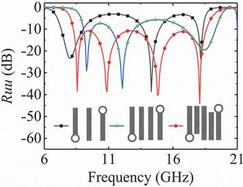
Figure 2 Simulated of the FSSGMs with 3, 4, or 5 metals in each grating.
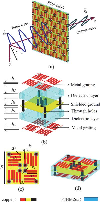
Figure 3 (a) Configuration of the proposed FSSMGs, (b) exploded view, (c) top view, (d) 3D view.
Figure 3 shows the final configuration of the proposed FSSMGs. The unit consists of four GVG modules. In each GVG structure, the receiving metal grating and the transmitting metal grating are etched on a dielectric substrate (F4BM265, , ) and connected by a metalized via, which contributes a unit. The four GVG modules are placed with a fourfold rotationally symmetric method, thus can effectively convert waves in arbitrary polarization direction, resulting in polarization insensitivity and incidence stability. The dimensions of the parameters in Fig. 1 are mm, mm, mm, mm, mm, mm, mm, mm, and mm.
2.2 Operation principle
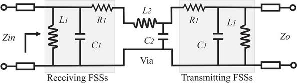
Figure 4 Equivalent circuit model of a transmission-type polarization converter.
The sub-unit of FSSMGs consists of a receiving grid on the top layer, metalized vias, and an emitting grid on the bottom layer. The receiving and the emitting grid structure can be equivalent to parallel resonant circuits (), and the metalized vias (waveguide structures) can be represented by a series resonant circuit ( and are related to electric energy storage, magnetic energy storage and medium loss), as shown in Fig. 4.
The frequency response of FSSMGs can be illustrated by S-parameters, which can be defined as [25]:
| (1) | ||
| (2) |
where , and are the elements of the two-port network transmission matrix. According to transmission line theory, the transmission matrix of the FSSMGs can be represented as:
| (7) | ||
| (10) | ||
| (13) | ||
| (14) |
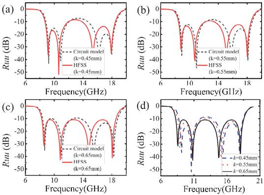
Figure 5 at calculated by equivalent circuit models and HFSS when (a) mm, (b) mm, (c) mm, and (d) simulated by HFSS at different k values.
During transmission, the phase is delayed and caused by the metalized vias in FSSMGs. Equation (14) represents the phase constant of the metalized vias, where f is the operation frequency, and are the inductance and capacitance per unit length of the metalized vias, respectively, and is the characteristic impedance. The values of the inductance and capacitance of the polarization converter in the form of an infinite array can be optimally designed through the following equation [16]:
| (15) |
where and represent for the magnetic and electric energies stored around the grid cell, and denotes the currents associated with the inductance and capacitance of the grid, respectively.
To verify the analyzed results, the equivalent circuit simulator is utilized to simulate the transmission and reflection coefficients. The extracted current parameters used in the equivalent circuit are: nH, pF, nH, pF, . The simulated results by the equivalent circuit simulator are shown in Fig. 5, which are compared with results simulated by ANSYS HFSS at the polarization angle of 0∘. From analysis of the equivalent circuit in Fig. 1, it can be obtained that the width of the grating metal has a significant impact on S-parameters. Therefore, Fig. 5 demonstrates the compared results of different parameter k. It can be illustrated from Figs. 5 (a–c) that the results by equivalent circuit simulator are in good agreement with those by HFSS. Moreover, it can be obtained from Fig. 5 (d) that the widest bandwidth of the proposed FSSMGs is observed at a k value of 0.65 mm.
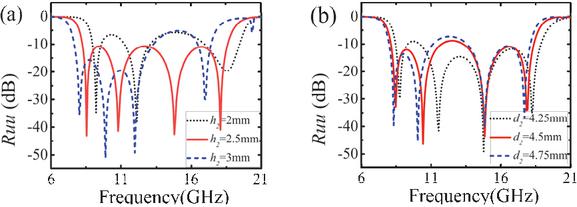
Figure 6 Simulated of proposed FSSMGs with different values of main parameters, including and .
Full wave simulation based on Floquet mode is conducted in ANSYS HFSS. All parameters, except k, (dimension of the sub-unit) and (thickness of the dielectric substrates), have significant impact on the simulation results. Figure 6 depicts the simulated of the proposed FSSMGs with different values of and . It can be seen from Fig. 6 (a) that, when increases, the resonant frequencies move to the low frequency band, and the bandwidth of is wider when mm. Therefore, parameter is chosen as 2.5 mm, which is also beneficial for processing. In Fig. 6 (a), when increases, the resonant frequencies moves to the low frequency band. Moreover, the dimension of has an effect on the two lower resonant frequencies. To ensure the value to be lower than 10 dB, is selected as 4.5 mm.
In order to visually validate the polarization insensitivity of FSSMGs, the electric field vector distributions at the receiving and radiating ends were analyzed at 8.56 GHz. The receiving and radiating ports of the FSSMGs unit were placed on two mutually perpendicular planes, with the angle between the receiving plane and the x-axis set as . Figure 7 depicts the electric field vector distribution on the receiving and radiating planes of FSSMGs at polarization angles of , 15∘, 30∘, and 45∘. It can be observed that the electric field direction of incident and transmitted waves are perpendicular to each other, which demonstrates the cross-polarization conversion of the proposed converter. The energy levels of transmitted waves at the four polarization angles are almost identical, which verifies the polarization-insensitivity of the designed FSSMGs.
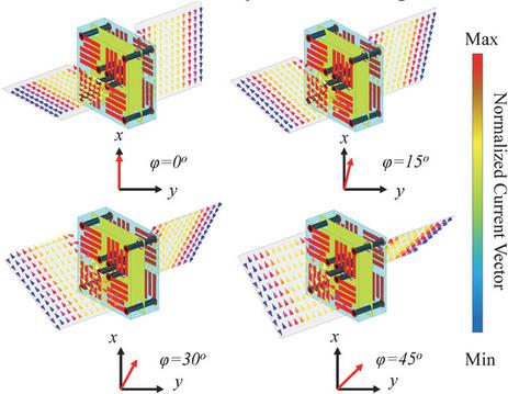
Figure 7 Electric field vector distribution at input and output ports of the FSSMGs for an incident LP wave in (a) , (b) , (c) , and (d) .
3 ANALYSIS OF SIMULATION RESULTS
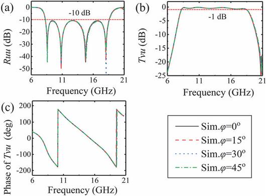
Figure 8 Simulated (a) , (b) , and (c) phase of of FSSMGs when is equal to 0∘, 15∘, 30∘, 45∘, respectively.
FSSMGs can be considered as a dual-port device, and its transmission characteristics can be demonstrated using S-parameters. When the polarization angle of electromagnetic wave is not equal to 0 or 90 deg, the performance of the polarization converter can be demonstrated by the co-polarized reflection coefficient () and cross-polarized transmission coefficient (). The proposed polarization converter is stable for any angle of polarization. Due to the rotational symmetry of the structure, the results at the polarization angle of 0–45∘ are taken as examples to analyze the performance of the polarization converter. Full wave simulation based on Floquet mode is conducted in ANSYS HFSS, and the 3D frequency-domain solver is used to obtain the propagation characteristic of the FSSMGs at copolar- and cross-polarized incidence within the required frequency band.
Figure 8 shows the simulated amplitude of , and the phase of at polarization angles from 0∘ to 45∘. It can be found that the at different polarization angles are approximately consistent, which demonstrates the polarization insensitivity of the proposed converter. The frequency bandwidth in Fig. 8 (a) at the of less than 10 dB is from 8.25 GHz to 18.7 GHz, which is consistent with the bandwidth from 8.17 GHz to 18.5 GHz at of more than 1 dB in Fig. 8 (b). Therefore, the polarization converter can realize polarization conversion in the band from 8.17 GHz to 18.5 GHz.
| (16) | |
| (17) |
For the purpose of evaluating the polarization conversion efficiency, the PCR and energy conversion ratio (ECR) [13] of are defined and expressed in equations (16) and (17).
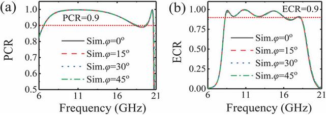
Figure 9 Simulation results at , 15∘, 30∘, and 45∘. (a) PCR. (b) ECR.
Figure 9 depicts the PCR and ECR of the proposed converter at different polarization angles. It can be seen that the PCR value is more than 90% in the frequency range of 6.72–19.1 GHz, and the maximum PCR value reaches 97% at 11 GHz. Figure 8 (b) shows that the ECR value in the band of 8.28–18.14 GHz is averagely more than 90%. Moreover, the simulated results at different polarization angles in Fig. 8 are completely consistent. In conclusion, the proposed FSSMGs exhibits high polarization conversion efficiency and high polarization insensitivity.
Furthermore, the amplitude and phase of under oblique incidence were simulated under the oblique incidence from 0∘ to 45∘, as depicted in Figs. 10 (a) and (b), respectively. Due to polarization-insensitive characteristic, was defined as 0∘ in Fig. 9. It can be illustrated that, the proposed FSSMGs has excellent oblique incidence stability in the frequency band of 8.17–12 GHz (38.0%) and 15–18.5 GHz (20.9%) when the incident angle is less than 45∘.
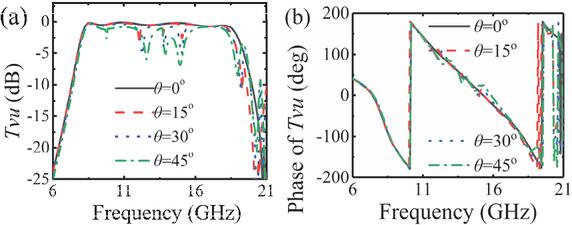
Figure 10 The (a) amplitude and (b) phases of at the incident angle- of 0∘, 15∘, 30∘, and 45∘.
4 EXPERIMENTAL VERIFICATION
To verify simulations, a prototype of the polarization converter with units was made, as shown in Fig. 11. The part inside the dashed rectangle is enlarged. The prototype has a size of mm. The transmission characteristic parameters of the FSSMGs were measured using two standard horn antennas in a microwave anechoic chamber, and the distance between horn antennas and the fabricated converter is 100 cm. The installation diagram and the measured environment is shown in Fig. 12.
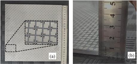
Figure 11 Fabrication of the proposed FSSMGs.
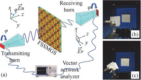
Figure 12 Experimental setup.
Figure 13 illustrates the measured amplitude of and at , 15∘, 30∘, and 45∘. It is evident that the curves at different are almost coincident, which validates the polarized insensitivity of the proposed converter. The bandwidth of the measured ranges from 8.21 GHz to 18.62 GHz (77.6%), closely aligning with simulated ones.
Finally, to emphasize the benefits of the proposed FSSMGs, a comparison with several related PICPCs is provided in Table 1. Compared with existing PICPCs, the FSSMGs introduced in this letter demonstrates a broader transmission bandwidth along with higher polarization conversion efficiency.
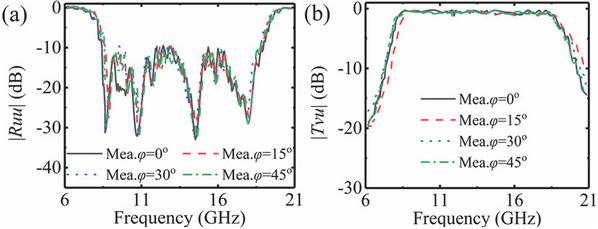
Figure 13 Measured and simulation results: (a) and (b) with polarization angles at , 15∘, 30∘, and 45∘.
Table 1 Data comparison of the most advanced polarization-insensitive polarization converters
| Ref. | Unit Cell Dimension | Num. of Layer | Bandwidth (GHz) | PCR | ECR |
| [8] | 0.23 | 2 | 9.14-9.5 (4%), 10.9-11.4 (5.1%) | / | 79% |
| [9] | 0.31 | 3 | 5.5-6.18 (12%) | 90% | 50% |
| [10] | 1.13 | 3 | 9.5-10.9 (13.7%) | 99% | 95% |
| [11] | 0.35 | 7 | 26-32 (21%) | / | 50% |
| [12] | 0.33 | 2 | 8.4-11.2 (27.2%) | 92% | 60% |
| This work | 0.16 (8.21 GHz) | 3 | 8.21–18.62 (77.6%) | 94% | 92% |
5 CONCLUSION
A novel FSSMGs is proposed to achieve insensitive polarization conversion in an ultra-wide bandwidth. The unit is made up of four rotationally symmetric GVG modules. Compared to existing PICPCs, the proposed FSSMGs demonstrates an ultra-wide bandwidth by designing innovative multiple-resonance unit. Polarization conversion occurs within the band 8.21–18.62 GHz (77.6%), during which the polarization conversion efficiency is higher than 90% and the proposed converter can achieve polarization conversion in arbitrary polarized angles. The high polarization conversion efficiency and ultra-wide bandwidth suggest potential prospects in applications such as X/Ku communication for military unmanned aerial vehicles and multi-band polarization multiplexing in satellite communications.
ACKNOWLEDGMENT
This work was supported by Technology Innovation Leading Program of Shaanxi (Program No. 2024ZC-YYDP-33).
REFERENCES
[1] J. Huang, T. K. Wu, and S. W. Lee, “Tri-band frequency selective surface with circular ring elements,” IEEE Trans. Antennas Propag., vol. 42, no. 2, pp. 166–175, 1994.
[2] R. Panwar and J. R. Lee, “Progress in frequency selective surface based smart electromagnetic structure: A critical review,” Aerosp. Sci. Technol., vol. 66, pp. 216–234, 2017.
[3] H. A. Zebker and J. J. Van Zyl, “Imaging radar polarimetry: A review,” Proc. IEEE, vol. 79, no. 11, pp. 1583–1606, Nov. 1991.
[4] W. Li, S. Gao, Y. Cai, Q. Luo, M. Sobhy, G. Wei, P. Xu, J. Li, C. Wu, and Z. Cheng, “Polarization-reconfigurable circularly polarized planar antenna using switchable polarizer,” IEEE Trans. Antennas Propag., vol. 65, no. 9, pp. 4470–4477, Sep. 2017.
[5] R. Singh, E. Plum, C. Menzel, C. Rockstuhl, A. K. Azad, R. A. Cheville, F. Lederer, W. Zhang, and N. I. Zheludev, “Terahertz metamaterial with asymmetric transmission,” Phys. Rev. B, Condens. Matter, vol. 80, no. 15, Oct. 2009.
[6] G. Cheng, L. Si, P. Tang, Q. Zhang, and X. Lv, “Study of symmetries of chiral metasurfaces for azimuth-rotation-independent cross polarization conversion,” Opt. Exp., vol. 30, no. 4, p. 5722, 2022.
[7] S. Y. Wang, J.-D. Bi, W. Liu, W. Geyi, and S. Gao, “Polarization insensitive cross-polarization converter,” IEEE Trans. Antennas Propag., vol. 69, no. 8, pp. 4670–4680, Aug. 2021.
[8] W. Liu, L. Zhang, J. Ke, J. Liang, C. Xiao, Q. Cheng, and T. Cui, “Metasurface-based broadband polarization-insensitive polarization rotator,” Opt. Exp., vol. 30, no. 19, p. 34645, Sep. 2022.
[9] J. Zhu, Y. Yang, J. Lai, and J. Nulman, “Additively manufactured polarization insensitive broadband transmissive metasurfaces for arbitrary polarization conversion and wavefront shaping,” Adv. Opt. Mater., vol. 10, no. 21, Nov. 2022.
[10] J. Li, Y. Yuan, Q. Wu, and K. Zhang, “Bi-isotropic Huygens’ metasurface for polarization-insensitive cross-polarization conversion and wavefront manipulation,” IEEE Transactions on Antennas and Propagation, vol. 72, no. 3, pp. 2445–2454, Mar. 2024.
[11] K. Li, Y. Liu, Y. Jia, and Y. J. Guo, “A circularly polarized high-gain antenna with low RCS over a wideband using chessboard polarization conversion metasurfaces,” IEEE Trans. Antennas Propag, vol. 65, no. 8, pp. 4288–4292, Aug. 2017.
[12] M. Anh Nguyen and G. Byun, “Anisotropic metagratings with a polarization-selective layer for anomalous wide-angle reflection and polarization conversion,” IEEE Trans. Antennas Propag, vol. 72, no. 10, pp. 7961–7969, Oct. 2024.
[13] M. Yang, F. Lan, Y. Zhang, L. Qi, G. He, Y. Pan, T. Song, L. Wang, P. Mazumder, H. Zeng, and Z. Yang, “Collective-coupling enhanced ultrabroadband linear polarization conversion on zigzag-split metasurfaces,” IEEE Trans. Antennas Propag, vol. 71, no. 6, pp. 5001–5013, June 2023.
[14] E. Arnieri, F. Greco, L. Boccia, and G. Amendola, “A SIW-based polarization rotator with an application to linear-to-circular dual-band polarizers at K-/Ka-band,” IEEE Trans. Antennas Propag., vol. 68, no. 5, pp. 3730–3738, May 2020.
[15] H. B. Wang and Y. J. Cheng, “Single-layer dual-band linear to-circular polarization converter with wide axial ratio bandwidth and different polarization modes,” IEEE Trans. Antennas Propag., vol. 67, no. 6, pp. 4296–4301, June 2019.
[16] P. Xu, W. X. Jiang, S. Y. Wang, and T. J. Cui, “An ultrathin cross-polarization converter with near unity efficiency for transmitted waves,” IEEE Trans. Antennas Propag, vol. 66, no. 8, pp. 4370–4373, Aug. 2018.
[17] V. Singh, S. Bhattacharyya, and R. Agrahari, “A low-profile tri-functional metasurface toward polarization conversions and absorption,” IEEE Antennas and Wireless Propagation Letters, vol. 23, no. 9, pp. 2593–2597, Sep. 2024.
[18] P. Naseri, S. A. Matos, J. R. Costa, C. A. Fernandes, and N. J. G. Fonseca, “Dual-band dual-linear-to-circular polarization converter in transmission mode application to K/K a-band satellite communications,” IEEE Trans. Antennas Propag., vol. 66, no. 12, pp. 7128–7137, Dec. 2018.
[19] A. A. Omar, Z. Shen, and S. Y. Ho, “Multiband and wideband 90∘ polarization rotators,” IEEE Antennas Wireless Propag. Lett., vol. 17, no. 10, pp. 1822–1826, Oct. 2018.
[20] W. Fu, Y. Cai, P. Mei, G. Frølund Pedersen, and S. Zhang, “Electronically reconfigurable filtering reflectarray antenna using polarization conversion elements with controllable conversion zeros,” IEEE Trans. Antennas Propag., vol. 72, no. 9, pp. 7359–7364, Sep. 2024.
[21] R. T. Ako, W. S. L. Lee, S. Atakaramians, M. Bhaskaran, S. Sriram, and W. Withayachumnankul, “Ultra-wideband tri-layer transmissive linearpolarization converter for terahertz waves,” APL Photon., vol. 5, no. 4, Apr. 2020.
[22] M. Yang, F. Lan , Y. Zhang, L. Qi, G. He, Y. Pan, T. Song, L. Wang, P. Mazumder, H. Zeng, and Z. Yang, “Collective-coupling enhanced ultrabroadband linear polarization conversion on zigzag-split metasurfaces,” IEEE Trans. Antennas Propag, vol. 71, no. 6, pp. 5001–5013, June 2023.
[23] D. Feng, “A new equivalent circuit of miniaturized frequency selective surface,” in Proceedings of 2014 3rd Asia-Pacific Conference on Antennas and Propagation, Harbin, China, pp. 1363–1365, 2014.
[24] P. Xu, W. X. Jiang, S. Y. Wang, and T. J. Cui, “An ultrathin cross-polarization converter with near unity efficiency for transmitted waves,” IEEE Trans. Antennas Propag, vol. 66, no. 8, pp. 4370–4373, Aug. 2018.
[25] S. Y. Wang, J. D. Bi, W. Liu, W. Geyi, and S. Gao, “Polarization insensitive cross-polarization converter,” IEEE Trans. Antennas Propag., vol. 69, no. 8, pp. 4670–4680, Aug. 2021.
BIOGRAPHIES

Xueyan Song was born in Henan Province, China, in 1989. She received the B.E. degree in 2012 and the Ph.D. degree in 2018 from Xidian University. She joined Xi’an University of Posts and Telecommunications in 2018. Her research interests include metasurface, antennas, and reflector antennas.

Hua Lu was born in Shaanxi, China, in 1998. He holds the Master of Engineering degree from the School of Electronic Engineering, Xi’an University of Posts and Telecommunications. His current research interests include metasurface and polarization converter.

Shaochen Yang was born in Shaanxi, China, in 2002. He is currently pursuing a Master of Engineering degree in the School of Electronic Engineering, Xi’an University of Posts and Telecommunications.

XuPing Li was born in Xi’an, Shanxi, China, in 1981. He received the Ph.D. degree in electromagnetic fields and microwaves from Xidian University, Xi’an, in 2015. In January 2019, he was transferred to Xi’an University of Posts and Telecommunications as leader of the phased array antenna technology research team. His research programs focus on phased array antennas.

Chao Xiong was born in Jiangxi, China, in 2004. He is currently pursuing B.E. degree in the school of Electronic Engineering, Xian University of Posts and Telecommunications.

YunQi Zhang was born in BaoTou, Inner Mongolia, China, in 1986. He received the Ph.D. degree from Xidian University in 2015. He is currently working in Xi’an University of Posts & Telecommunications. His research interests include GPS antenna, CP antenna, omnidirectional antenna and antenna array designs.

Xin Wang received his master’s degree in 2015 from Xidian University, China. Subsequently, he worked at several major communication equipment manufacturers. In 2024, he received his Ph.D. from Xidian University. He is currently employed at Xi’an University of Posts & Telecommunications, with research interests in reconfigurable metasurfaces for active power amplifiers, power amplifiers, and phased array antennas.
ACES JOURNAL, Vol. 40, No. 10, 1002–1009
DOI: 10.13052/2025.ACES.J.401005
© 2025 River Publishers