An S-Band Low-Probability Intercept Radar Antenna With Low Sidelobe Level
Zhengliang Lv1, Shuai Yan1, Zizhen Zheng1, Yi Zeng2, and Xing Wang2
1China Academic Electronic and Information Technology
Beijing 100041, China
lvzhengliang@cetc.com.cn, Yangshuai6@cetc.com.cn, bitzhengzizhen@163.com
2National Key Laboratory of Radar Detection and Sensing
Xi’an, Shaanxi 710071, China
yizeng@stu.xidian.edu.cn, wangxing@mail.xidian.edu.cn
Submitted On: July 03, 2025; Accepted On: September 10, 2025
Abstract
A half-wave dipole array antenna design for S-band low probability of intercept (LPI) radar is presented. The antenna structure comprises linearly polarized dipole elements. A 24-column Taylor distribution weighted feed in the azimuth plane realizes low sidelobe level (SLL) of 26.0 dB. The antenna achieves an operational bandwidth of 100 MHz with a voltage standing wave ratio (VSWR) below 1.4. A prototype was fabricated and measured for verification. The measured gain is 22.3 dBi, with half-power beamwidth (HPBW) of 6.5∘ and 24.5∘ in azimuth and elevation, respectively. Results show that the array scans from 45∘ to 45∘ with a gain loss below 2.1 dB, while maintaining an SLL under 20.2 dB across this wide scanning range.
Keywords: Array antenna, high-gain, low probability of interception (LPI) radar, low sidelobe level (SLL)..
1 INTRODUCTION
Low probability of intercept (LPI) radar is a new radar system which uses a variety of technologies to prevent radar signals from being intercepted by the enemy intercept receiver. Hence, much research and design are carried out focused on LPI radar [1, 2, 3]. It is generally believed that the time taken by the enemy to intercept the radar depends on the main lobe gain, sidelobe level (SLL) and beam width of the radar antenna. Low probability of interception radar should be equipped with a planar antenna array, which has high gain and low SLL performances.
Sidelobe manipulation techniques for antenna array have been developed by many researchers. The common approach of reducing SLLs in array antennas is amplitude control and phase correction by the feeding network. Waveguide slot array antennas with Taylor’s distribution have been proposed for radar systems [4, 5, 6]. In [6], array antennas combined with Schelkunoff’s unit circle technique have achieved less than 28.5 dB SLL by utilizing Taylor synthesis. Taylor’s distribution can also be used in slots array antenna with T-junction power divider [7], slots array antenna with inverted microstrip gap waveguide [8], slotted ridge waveguide antenna array [9] and monopulse slotted antenna with gap waveguides [10]. Besides Taylor’s distribution, the Chebyshev amplitude distribution can be used in a series-fed linear dielectric resonator antenna array to get a low SLL [10]. In [11], Dolph-Chebyshev distributions are utilized by periodic stub-loaded slow wave transmission line feed networks to reach low SLL performances in compact series-fed microstrip patch arrays.
Another method for sidelobe manipulation is modifying the structure or position of feeding line in microstrip antenna arrays. The U-shaped series-feed network and corner series-feed network are used in linear microstrip antenna arrays to provide low SLL and low cross polar level in [12]. In addition, the feeding line in a microstrip patch array antenna was modified as the step-impedance microstrip line to decrease the SLL in [13]. In [14], the two halves of the structure were fed in parallel and each arm was fed in a series-series feed network to achieve the low SLL of 26.5 dB. However, the impedance bandwidth in the X-band was only 5.3% (VSWR 1.92).
This paper is organized as follows. Section 2 presents the required technical specifications for the antenna. Section 3 details the theory of LPI radar and the antenna design process. Section 4 covers antenna fabrication and measurement. Conclusions are provided in section 5.
2 TARGET SPECIFICATIONS AND CONFIGURATIONS OF ANTENNA
Table 1 defines target specifications for the scaled model sample of LPI radar antenna. The proposed antenna should have linear-horizontal polarization and achieve wide-scanning performance with 45∘ in the azimuth plane.
Table 1 Target specifications of the antenna
| Specification | Value |
| Frequency | 2.25 GHz |
| Array Form | elements |
| Size | mm |
| VSWR | 1.6 (per element) |
| 1.4 (average) | |
| Polarization | Linear-Horizontal |
| SLL (Azimuth) | 26 dB max |
| HPBW (Azimuth/Elevation) | 6.8∘/26∘ max |
| Scanning Angle (Azimuth) | 45∘ min |
| Gain (0∘/30∘/45∘ in azimuth) | 21.7 dBi/20.7 dBi/18.8 dBi min |
| Weight | 43000 g |
3 DESIGN AND SIMULATION
LPI radar is designed to minimize the probability of its signals being intercepted by an enemy receiver. This probability is quantified by the intercept probability factor . Based on the LPI radar theory in [15], the intercept probability factor is defined as:
| (1) |
where represents the interception range of intercept receiver and represents the detection range of radar. They can be expressed as:
| (2) | ||
| (3) |
where is the radar transmitter power, is the radar transmitter power with loss of , which can be taken as , is the gain of radar’s transmit antenna, is the gain of radar’s receive antenna, is the gain of the intercept receiver antenna in the direction of radar, is the gain of the radar’s transmit antenna in the direction of the intercept receiver, and are the sensitivity of intercept receiver and radar receiver, and are the system loss factor of intercept receiver and radar receiver, is the wavelength of transmitted signal, and is radar cross-section of target.
When the maximum operating range of the radar is determined, the intercept probability factor of radar system with common antenna can be written as:
| (4) |
Without considering sensitivity and system loss factors, the intercept probability factor has the following relationship with the radar’s transmit antenna and intercept receiver antenna:
| (5) |
According to Equation (5), besides the influence of intercept receiver antenna, the intercept probability factor can be reduced by increasing the gain of the radar’s transmit antenna. Meanwhile, the intercept probability factor is proportional to the square root of the radar’s transmit antenna SLL when the intercept receiver intercepts the radar in the sidelobe direction. Thus, low SLL antenna is also an important LPI characteristic.
Hence, we tend to design an antenna with high gain of main lobe and low level of sidelobe. Initially, the half-wave dipole antenna is chosen as a fundamental form for high gain characteristic. Then, the SLL is reduced effectively by Taylor distribution in the feeding design. During the process, all the simulated data are provided by the commercial electromagnetic simulation tool HFSS.
3.1 Antenna element design
A half-wave dipole antenna is one of the most widely used antenna types in antenna engineering, including communication, radio, television, navigation and other engineering systems. When the half-wave dipole antenna is directly placed, the radiation performance is omnidirectional radiation. Therefore, a reflecting plate is loaded to give the antenna directional radiation. At the same time, referring to the radiation principle of Yagi-Uda antenna, the directional structure is added to improve the directional radiation performance of the antenna element. Figure 1 shows the final structure of the antenna element (purple) and epoxy glass fibrous cloth used as the radome (green).
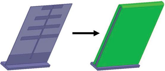
Figure 1 Structure of the proposed antenna element with radome.
Figure 2 shows the measured 3-D radiation pattern of the proposed antenna element where the peak gain reaches 7.6 dBi. The simulated bandwidths for VSWR1.4 are 145 MHz (6.4%). The antenna array element has good directional radiation characteristics, simple installation process and is easy to use.
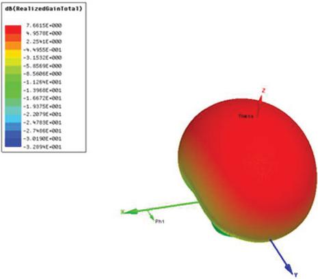
Figure 2 Simulated 3-D radiation pattern of the antenna element.
3.2 Array synthesis
The antenna array consists of 48 units, with two rows of elevation plane and 24 columns of azimuth plane, as shown in Fig. 3 (). The AN and BN represent the N-th element of two rows, respectively.
Element spacing in the elevation plane is set as 150 mm () and each two array elements in the same elevation plane are designed with equal amplitude and phase feeding by power division units, which can narrow the beam width in the elevation plane to improve gain. The 24 column Taylor distribution weighted feed in the azimuth plane reduces the pattern sidelobe. After sidelobe reduction technique employment, the SLL of the array pattern is reduced while the main lobe width becomes wider. Relatively, the lower the SLL, the wider the main lobe width. In order to fulfill the requirements of beam width, the element spacing is increased to and finally selected at 76.5 mm (), which can improve the gain and effectively control the beam width. It’s worth noting that the element spacing shall not be so large as to cause grating lobes during scanning.
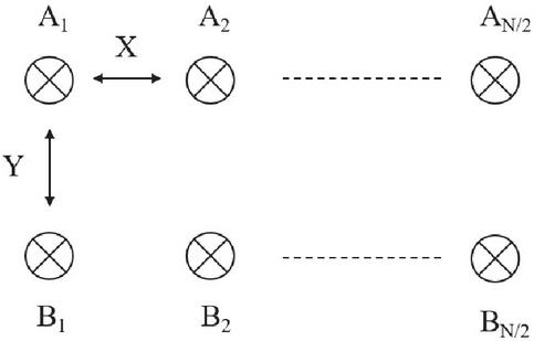
Figure 3 Schematic diagram of array layout.
The antenna array elements are fed by the phase-shifting attenuation module to realize antenna azimuth scanning. The phase-shift attenuation module is mainly used to test whether the technical parameters of the phase scanning antenna array fulfills the design indicators under different frequencies, different wave positions, different amplitude weighted values and other conditions.
3.3 Array configuration and simulation
The 3-D view and front view diagrams of the proposed antenna are shown in Fig. 4. The antenna is mainly composed of antenna element, power divider, auxiliary unit, reflecting plate, phase shift attenuation module, installation framework and RF front-end.
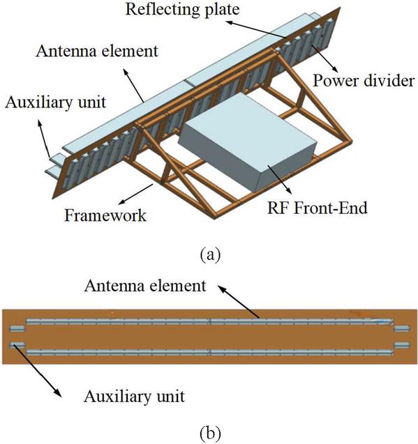
Figure 4 (a) 3-D view and (b) front view of the proposed antenna.
As shown in Fig. 4 (a), the radiating antenna consists of four groups of antenna cell with a total of 48 antenna elements. Four auxiliary units are located at both ends of the radiating antenna, with a pitch spacing of 76.5 mm. A total of 26 power dividers are located behind the antenna element, connected to the antenna element and auxiliary unit by blind plugs of Blind-mate A (BMA) connectors, and fixed with the reflecting plate through screws. Figure 4 (b) shows the front view of the antenna array. The radiating antenna array is composed of 48 elements with two rows of elevation plane and 24 columns of azimuth plane.
Figure 5 shows the E-plane simulated array scanning patterns at 2.25 GHz. When the phase scan of the radar antenna is 0∘, the maximum gain of simulation results is 22.72 dBi with the first SLL of 29.6 dB. Also, high beam gains of 21.8 and 19.9 dBi are obtained in the scan angle of 30∘ and 45∘, respectively.
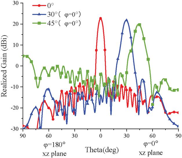
Figure 5 Simulated scanning performance of the proposed antenna array at 2.25 GHz.
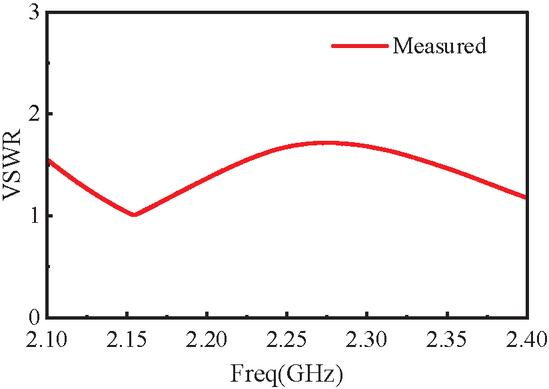
Figure 6 Measured VSWR of antenna array.
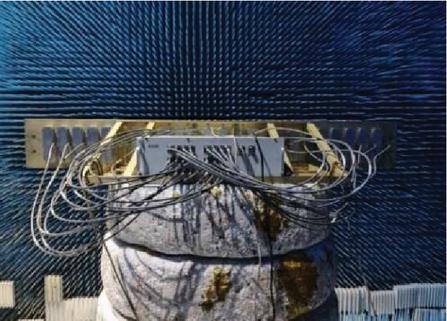
Figure 7 Antenna fabricated model in measurement environment.
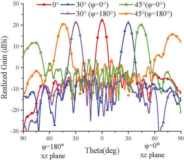
Figure 8 Measured scanning performance of the proposed antenna array at 2.25 GHz.
Table 2 Realized gain in different scan angles
| Scan angle in | Realized gain | SLL at |
| xz plane (deg) | at 2.25 GHz (dBi) | 2.25 GHz (dB) |
| 0 | 22.3 | 26.0 |
| 30 () | 21.1 | 26.4 |
| 45 () | 20.2 | 20.2 |
| 30 () | 21.2 | 28.4 |
| 45∘ () | 20.7 | 20.4 |
Table 3 Performance comparison of the array antennas
| Ref. | Size () | Freq. (GHz) | BW | VSWR | Gain (dBi) | HPBW (deg) | SLL (dB) | ||
| E-plane | H-plane | E-plane | H-plane | ||||||
| [4] | 9.3 | 4.3% | 1.37 | 37.7 | 3.8 | 1.3 | -17 | -22.5 | |
| [6] | 8.9 | 2.8% | 1.43 | 23.2 | 8.9 | 9 | -28.5 | -29.6 | |
| [9] | 24.1 | 1.03% | 1.92 | 22.3 | 54.4 | 3.2 | -19.6 | -29.8 | |
| [13] | 9.41 | 1.9% | 1.92 | 21.3 | 8.1 | 41.8 | -27.8 | -21.4 | |
| [14] | 9.35 | 5.3% | 1.92 | 24.0 | 4.5 | 21.5 | -26.2 | -19.7 | |
| This Work | 2.25 | 4.4% | 1.4 | 22.3 | 6.5 | 24.5 | -26.0 | N/A |
4 EXPERIMENTAL VERIFICATION AND RESULTS
In this section, a prototype of the proposed antenna array is fabricated and measured to verify its feasibility. The total dimension of antenna is mm with a weight of 42.8 kg, while the radiating aperture is mm.
The voltage standing wave ratio (VSWR) of the antenna is measured by a network analyzer, as shown in Fig. 6. The VSWR of each array element is less than 1.8. The antenna electrical performance test is validated in a microwave anechoic chamber as shown in Fig. 7.
The scanning performance of the fabricated antenna array is measured and shown in Fig. 8. A maximum realized gain of 22.3 dBi can be obtained at 2.25 GHz with the low SLL of 26.0 dB. Table 2 shows the realized gain and SLL of proposed antenna at different scan angles.
The performance of the proposed antenna is benchmarked against existing antennas in the literature in Table 3. The proposed design exhibits several advantageous features, including a realized gain of 22.3 dBi, a SLL of 26.0 dB, a compact size of mm2, and a scanning capability of up to 45∘ with only a 2.1 dB gain loss.
5 CONCLUSION
This paper proposes an S-band half-wave dipole antenna with low SLL. The feed network employs a 24-column Taylor distribution weighting to reduce the pattern sidelobes. Results demonstrate an operational bandwidth of 4.4% (2.2–2.3 GHz) with an active voltage standing wave ratio 1.4. A prototype array was fabricated for the experimental validation. The antenna achieves a peak gain of 22.3 dBi, scanning over 45∘ with only 2.1 dB gain loss and SLL below 20.2 dB. Thus, the proposed antenna design serves as a suitable candidate for LPI radar applications.
References
[1] K. Chen, C. Xie, F. Yang, M. Huang, Y. Chen, and S.-W. Qu, “Integrated radar and communication design with low probability of intercept based on 4-D antenna arrays,” IEEE Trans. Antennas Propag., vol. 70, no. 9, pp. 8496–8506, Sep. 2022.
[2] K. Chen, S. Yang, Y. Chen, D. Yang, M. Huang, and S.-W. Qu, “LPI beamforming based on 4-D antenna arrays with pseudorandom time modulation,” IEEE Trans. Antennas Propag., vol. 68, no. 3, pp. 2068–2077, Mar. 2020.
[3] K. Chen, S. Yang, Y. Chen, S.-W. Qu, and J. Hu, “Transmit beamforming based on 4-D antenna arrays for low probability of intercept systems,” IEEE Trans. Antennas Propag., vol. 68, no. 5, pp. 3625–3634, May 2020.
[4] M. Atamanesh, A. Zahedi, and B. Abbasi-Arand, “Design, simulation, and fabrication of a high-gain low-sidelobe-level waveguide slot array antenna at X-band with zero beam tilts in both azimuth and elevation directions,” IEEE Antennas Wireless Propag. Lett., vol. 19, no. 5, pp. 811–815, May 2020.
[5] R. A. Bhatti, B.-Y. Park, Y.-T. Im, and S.-O. Park, “Design of a planar slotted waveguide array antenna for X-band radar applications,” J. Korean Inst. Electromagn. Eng. Sci., vol. 11, no. 2, pp. 97–103, June 2011.
[6] P. Kumar, A. Kedar, and A. K. Singh, “Design and development of lowcost low sidelobe level slotted waveguide antenna array in X-band,” IEEE Trans. Antennas Propag., vol. 63, no. 11, pp. 4723–4731, Nov. 2015.
[7] P. Liu, G. F. Pedersen, and S. Zhang, “Wideband low-sidelobe slot array antenna with compact tapering feeding network for E-band wireless communications,” IEEE Trans. Antennas Propag., vol. 70, no. 4, pp. 2676–2685, Apr. 2022.
[8] J. Liu, F. Yang, K. Fan, and C. Jin, “Unequal power divider based on inverted microstrip gap waveguide and its application for low sidelobe slot array antenna at 39 GHz,” IEEE Trans. Antennas Propag., vol. 69, no. 12, pp. 8415–8425, Dec. 2021.
[9] J. Chen, T. Hu, Y.-T. Zhao, L. Li, M. Bao, T. Su, and J. Ding, “Realization of high-gain low-sidelobe wide-sector beam using inductive diaphragms loaded slotted ridge waveguide antenna array for air detection applications,” IEEE Trans. Antennas Propag., vol. 70, no. 4, pp. 2698–2707, Apr. 2022.
[10] X. Cheng, X. Ming, J. Liu, X. Liu, J. Li, S. Gao, and A. A. Kishk, “Compact dual-polarized low sidelobe monopulse slot antenna array based on gap waveguide technology,” IEEE Trans. Antennas Propag., vol. 73, no. 2, pp. 1215–1220, Feb. 2025.
[11] J. Lin, W. Shen, and K. Yang, “A low-sidelobe and wideband series-fed linear dielectric resonator antenna array,” IEEE Antennas Wireless Propag. Lett., vol. 16, pp. 513–516, 2017.
[12] M. Li, Z. Zhang, M.-C. Tang, D. Yi, and R. W. Ziolkowski, “Compact series-fed microstrip patch arrays excited with Dolph-Chebyshev distributions realized with slow wave transmission line feed networks,” IEEE Trans. Antennas Propag., vol. 68, no. 12, pp. 7905–7915, Dec. 2020.
[13] R. Chopra and G. Kumar, “Series- and corner-fed planar microstrip antenna arrays,” IEEE Trans. Antennas Propag., vol. 67, no. 9, pp. 5982–5990, Sep. 2019.
[14] Z. Wang, J. Zhou, Y. Wang, Z. Zhu, S. Fang, and H. Liu, “A compact feeding network with radiation contribution for X-band marine radar antenna array applications,” Microw. Opt. Technol. Lett., vol. 61, no. 12, pp. 2819–2825, Aug. 2019.
[15] M. Pehlivan and K. Yegin, “X-band low-probability intercept marine radar antenna design with improved bandwidth and high isolation,” IEEE Trans. Antennas Propag., vol. 69, no. 12, pp. 8949–8954, Dec. 2021.
[16] P. Pace, Detecting and Classifying Low Probability of Intercept Radar, 2nd ed. Norwood, MA: Artech, 2008.
Biographies

Zhengliang Lv obtained his doctoral degree from Xidian University in 2014. He is currently a senior engineer at the China Academic Electronic and Information Technology. He has long been engaged in system integration, electromagnetic simulation, electromagnetic compatibility design, and other work related to major integrated electronic information systems. He has published over ten papers in core domestic and international journals such as the Chinese Journal of Electronics, Journal of Electromagnetic Waves and Applications, and Microwave Journal.

Shuai Yang received the B.Sc. degree in electronics and information engineering, and the Ph.D. degree in communication and information systems from the Harbin Institute of Technology (HIT), Harbin, China. His current research interests include electromagnetic metasurfaces, computational electromagnetics (CEM), and engineering electromagnetic compatibility (EMC).

Zizhen Zheng obtained her master’s degree from Beijing Institute of Technology, China, in 2024 and is currently an engineer at the China Academic Electronic and Information Technology. She is engaged in array antenna design, electromagnetic compatibility design, and has published multiple papers in journals such as Electronics and International Conference on Microwave and Millimeter Wave Technology.

Yi Zeng was born in Zhejiang, China, in 2000. He received the B.Eng. degree in electronic engineering from Xidian University, Xi’an, China, in 2022, where he is currently pursuing the Ph.D. degree in electronic science and technology. His focus is antenna analysis and design.

Xing Wang received the Ph.D. degree from Xidian University, Xi’an, China, in 2011. He is currently a Full Professor with the National Key Laboratory of Radar Detection and Sensing, Xidian University. His research interests include computational electromagnetic, fast algorithms for electromagnetic scattering and radiation, hybrid methods, and EMC analysis.
ACES JOURNAL, Vol. 41, No. 2, 180–185
DOI: 10.13052/2026.ACES.J.410209
© 2026 River Publishers