A V-Band Magnetoelectric Dipole Filtering Antenna Based on Rectangular Micro-Coaxial Lines
Nan Wang1, Ying Zhu2, Jing Wang3, Xinjiang Liu3, Chaoyu Feng4, Xinzhan Cai1, Xiaolan Zhang1, Xuefeng Zhao1, Wensen Wang1, Guang Dai3, and Jiawei Yang5
1Power Research Institute of State Grid Shaanxi Electric Power Corporation Limited
Xi’an 710100, China
18066661276@163.com, 969079361@qq.com, 18629051767@163.com, 78345659@qq.com, wangwensen@yeah.net
2School of Information and Communications Engineering
Xi’an Jiaotong University, Xi’an 710049, China
itszhuying@stu.xjtu.edu.cn
3State Grid Shaanxi Electric Power Corporation Limited
Xi’an 710048, China
44974545@qq.com, 670058424@qq.com, guang.gdai@gmail.com
4State Grid Shaanxi Electric Power Co. Ltd. Ultra High Voltage Company
Xi’an 710000, China
402266878@qq.com
5State Grid Shaanxi Electric Power Co. Ltd. Information and Communication Company
Xi’an 710000, China
792639824@qq.com
Submitted On: July 06, 2025; Accepted On: September 10, 2025
Abstract
A high-selectivity filtering magnetoelectric (ME) dipole antenna based on rectangular micro-coaxial lines (RMCLs) is presented, fabricated using micro-metal additive manufacturing (M-MAM) for V-band operation. The structure integrates two /4 resonators, one /2 resonator, and an ME dipole antenna, coupled through J/K-inverters realized as RMCL gaps and short-circuited stubs. Notably, while a standalone ME dipole inherently supports an impedance bandwidth over 30%, this design achieves a 5.04% operating bandwidth centered at 59.5 GHz after integrating filtering functionality. Simulations confirm a peak gain of 4.53 dBi within the passband, with cross-polarization consistently below 20 dB. A sharp gain roll-off to 10 dBi at 1.048 and 40 dB out-of-band suppression demonstrates exceptional frequency selectivity. Owing to inherent miniaturization, lightweight construction, and low-loss characteristics, the antenna exhibits significant potential for low-earth-orbit (LEO) satellite internet systems.
Keywords: Filter antenna, low-earth-orbit (LEO) satellite, magnetoelectric (ME) dipole antenna, V-band..
1 INTRODUCTION
The Q/V frequency band (40–75 GHz) encompasses dual sub-bands, namely the Q-band (40–50 GHz) and V-band (50–75 GHz), belonging to the millimeter-wave extremely high frequency (EHF) spectrum regime. Its ultra-wide bandwidth, high directivity, and low interference characteristics render it a crucial spectral resource for high-speed satellite communications, low-earth-orbit (LEO) internet access, and scientific research missions [1, 2, 3]. Corresponding radio frequency components must satisfy stringent requirements for ultra-miniaturization, ultra-low loss, and multifunctional integration. Filtering antennas with integrated filtering-radiating capabilities have emerged as a promising approach to address these challenges [4, 5].
Conventional filtering antenna implementations typically follow three approaches: (1) cascading antennas as terminal resonators with filter structures [6, 7, 8], (2) embedding band-rejection elements within feed networks to create transmission zeros [9], or (3) loading parasitic structures to modify radiation characteristics [10]. However, fabrication constraints at millimeter-wave frequencies often preclude direct application of these techniques. Recent studies have proposed solutions based on substrate integrated waveguide (SIW) [11], gap-waveguide (GWG) [12], frequency selective surfaces (FSS) [13, 14], and differential feeding networks [15]. Nevertheless, challenges persist, such as high integration complexity or excessive loss.
Notably, micro-metal additive manufacturing (M-MAM) technology, utilizing sequential thick-photoresist lithography and copper electroforming processes [16, 17, 18], enables the monolithic fabrication of multi-layer metallic structures without assembly. The rectangular micro-coaxial line (RMCL) structure developed based on this technology has been successfully applied in millimeter-wave antenna designs owing to its low transmission loss characteristics [19, 20, 21, 22]. However, the integration of filtering functionality within this structure remains an unresolved challenge.
This work proposes a novel filtering magnetoelectric (ME) dipole antenna implemented in RMCL technology. The design offers three key innovations: (1) a modular architecture permitting independent optimization of filtering and radiating sections before integration, (2) implementation of /4 resonators with short-circuited stubs connecting the feed and radiator, reducing dielectric support requirements and minimizing insertion loss, and (3) angular orientation of the dipole patches toward the ground plane to enhance front-to-back ratio (FBR) without increasing footprint. The prototype demonstrates 5.04% impedance bandwidth centered at 59.5 GHz, exceeding 40 dB out-of-band rejection, and stable cross-polarization below 20 dB.
2 FILTERING ANTENNA GEOMETRY AND ANALYSIS
2.1 Antenna geometry
The proposed filtering antenna is constructed using RMCLs based on M-MAM technology, with its monolithic 3D integration achieved through nine stacked copper layers. Figure 1 illustrates the RMCL fabrication schematic, wherein SU-8 support strips (, ) mechanically suspend the inner conductor to prevent inter-conductor short circuits. Release holes perforating the outer conductor walls facilitate post-processing removal of residual photoresist [18]. The characteristic impedance of the RMCL structure is determined by the inner conductor width and the conductor-to-outer-wall gap dimension , with optimized values of mm and mm achieving 50 impedance matching.
Figure 2 presents the three-dimensional topology of the integrated filtering antenna system, synergistically combining a hybrid resonator filter section with an ME dipole radiating element. The filtering compartment integrates two /4 resonators and a single /2 resonator interconnected through capacitive gap coupling, while employing short-circuited stubs for input/output port connections. The radiating element comprises vertical arms, a ground plane, and angularly oriented planar patches, where feeding is accomplished through a tapered trapezoidal transition structure with a probe pin directly coupled to an inclined patch to establish electric dipole excitation. Electromagnetically, co-directional surface currents on the inclined patches constitute the equivalent electric dipole, while the vertical arms in conjunction with the ground plane form /4 short-circuited patch structures generating complementary magnetic dipole radiation. By leveraging the modular design pattern inherent in RMCL technology and maintaining the dimensional consistency of the inner/outer conductors at the filter ports and antenna feed interfaces, independent optimization and seamless integration of the two functional modules are achieved. The optimized structural parameters are detailed in Table 1.
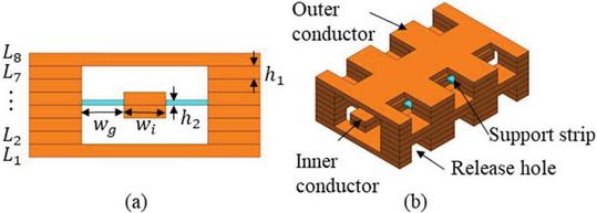
Figure 1 RMCL based on M-MAM. (a) Main view. (b) Side view. Main critical dimensions: and (unit: m).

Figure 2 Geometry of the proposed filtering antenna.
Table 1 Design parameters of the proposed filtering antenna (unit: mm)
| Para. | w | ks | kw | kl | ||
| Value | 1.66 | 0.20 | 0.35 | 0.05 | 0.236 | 0.507 |
| Para. | l | |||||
| Value | 5.71 | 0.89 | 2.21 | 0.89 | 0.321 | 0.321 |
| Para. | s | d | h | |||
| Value | 0.30 | 1.08 | 1.08 | 0.20 | 0.10 | 70∘ |
2.2 Filter design
Conventional capacitive-gap coupled filters typically require each resonator to exhibit a physical length of approximately /2 at the center frequency , with inter-resonator coupling achieved through adjacent open-end gaps. This coupling mechanism can be equivalently modeled as a J-inverter network [23]. However, such architectures inherently suffer from excessive longitudinal dimensions and substantial dielectric support requirements, significantly degrading insertion loss performance. To mitigate these limitations, this work innovatively introduces /4 resonators combined with K-inverters at the input/output ports, achieving over 40% reduction in overall filter dimensions while minimizing support structures to enhance transmission efficiency. The topological configuration of the proposed hybrid resonator filter is illustrated in Fig. 3.
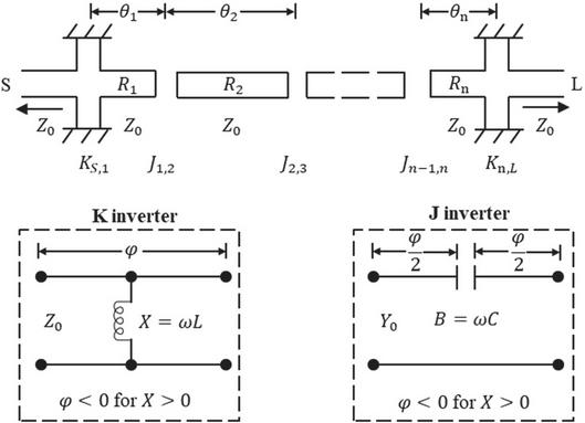
Figure 3 Illustration of a hybrid resonator filter structure with J/K-inverters.
Within the electromagnetic model of this filter, the electrical length of each resonator is determined by the following equation:
| (1) | |
| (2) |
where represents the phase contribution from adjacent coupling elements.
The physical length is then derived as:
| (3) |
where is the wavelength at .
For a 3rd-order filter centered at 60 GHz with 3.33% fractional bandwidth (FBW) and 20 dB return loss (RL), the Chebyshev low-pass prototype values [23] are given as:
Theoretical calculations determine the initial resonator lengths as:
Corresponding J/K-inverter equivalent circuit parameters are:
Leveraging the RMCL structure shown in Fig. 1, parameterized physical models of the J/K-inverters are established. Figure 4 demonstrates that the extracted J-inverter’s equivalent capacitance C exhibits a monotonic decrease with increasing gap distance d. Analysis of the K-inverter model in Fig. 5 reveals that the equivalent inductance L increases with stub length kl while decreasing with width kw. These parametric relationships provide theoretical foundations for determining initial J/K-inverter dimensions.
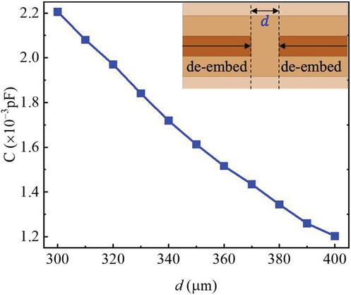
Figure 4 The value of C with different gaps d (including J-inverter).
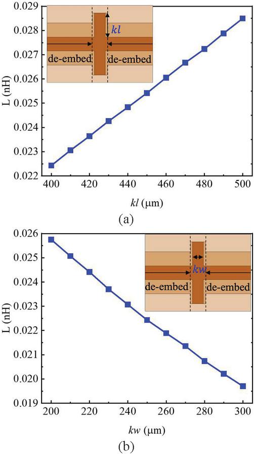
Figure 5 The value of L with different (a) length kl and (b) width kw (including K-inverter).
Using these models, a 3D electromagnetic model of the hybrid resonator filter is constructed in CST Microwave Studio. Following parametric optimization, the final design exhibits excellent agreement between full-wave simulation results (Fig. 6) and ideal Chebyshev responses, validating the theoretical approach. Key optimized dimensional parameters are comprehensively tabulated in Table 1.
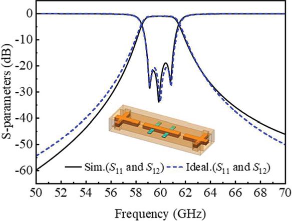
Figure 6 Full-wave response of the designed filter (solid lines). The ideal Chebyshev characteristic (dashed lines) is reported for comparison.
2.3 ME dipole antenna design
The evolutionary process of the ME dipole antenna design is depicted in Fig. 7. Antenna I (Ant. I) constitutes the baseline ME dipole configuration featuring a conventional -shaped feed and planar patches. Inspired by [24], structural modifications yield Antenna II (Ant. II): a bent probe pin directly coupled to the planar patches provides integrated excitation, while the inner conductor is reconfigured into a tapered trapezoidal topology. The final proposed radiator structure is realized through the angular orientation () of the planar patches toward the ground plane.
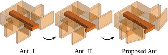
Figure 7 Design process of the proposed ME dipole antenna.
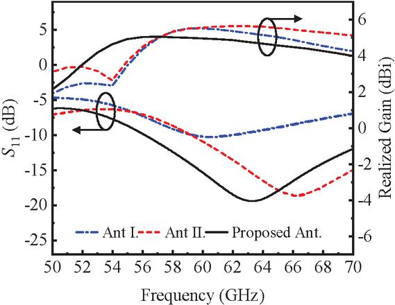
Figure 8 Simulated S11 and realized gains of Ant I, Ant II, and the proposed Ant.
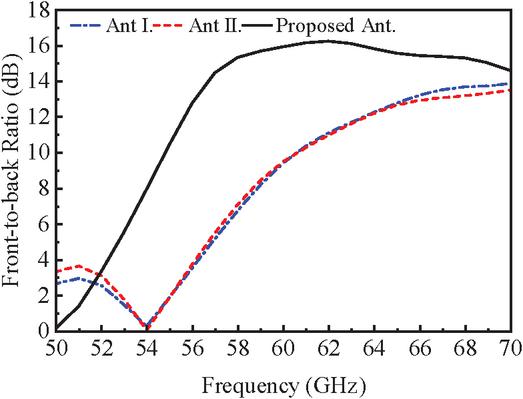
Figure 9 Simulated front-to-back ratio of Ant I, Ant II, and the proposed Ant.
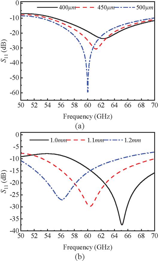
Figure 10 Simulated of the proposed ME dipole antenna with different values of (a) and (b) .
Figures 8 and 9 present the simulated and FBR for Ant I, Ant II, and the proposed antenna. Analysis indicates that while Ant I exhibits resonance at 60 GHz, but it suffers from severe impedance mismatch. The bent probe implementation in Ant II shifts the resonant frequency upward and achieves gain enhancement relative to Ant I, with the tapered transition, simultaneously improve impedance matching. However, both configurations demonstrate unsatisfactory FBR below 15 dB. The angular orientation technique proposed herein successfully elevates FBR to 16 dB while achieving a broad impedance bandwidth spanning 55–75 GHz ( dB) under the optimized parameters in Table 1.
To elucidate the underlying electromagnetic mechanisms, Fig. 10 investigates the influence of critical parameters and h on characteristics. Increasing primarily reduces resonant frequency while optimizing impedance matching, whereas parameter h predominantly modulates resonant frequency with negligible impact on matching. Current and electric field distributions in Fig. 11 reveal the physical origins: variation in h alters the resonant frequency by extending the effective current path length across the patch surface, while induces frequency-shifting effects through reduced vertical arm spacing during matching optimization.
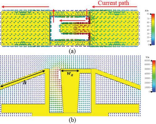
Figure 11 (a) Simulated current distribution on planar patches. (b) Simulated electric field distribution on the xoy plane.
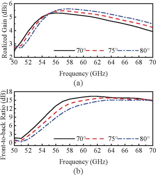
Figure 12 Simulated realized gain and front-to-back ratio of the proposed ME dipole antenna with different values of .
Figure 12 further quantifies the effect of the tilt angle on the radiation characteristics. It can be observed that the greater the inclination, which means the smaller , the FBR of the antenna increases. The backward radiation is suppressed to some extent with an unchanged ground floor, but this is accompanied by a sacrifice in gain.
2.4 Filtering antenna integration
Owing to dimensional consistency between inner and outer conductors in the RMCL utilized for both filter and antenna structures, direct interconnection enables system-level integration of the filtering antenna. Figure 13 presents comparative simulated and realized gain characteristics for the ME dipole antenna configurations with and without integrated filtering functionality. The proposed filtering antenna satisfies dB impedance matching across 58–61 GHz. Although the incorporated filter structure introduces insertion loss, it significantly enhances frequency selectivity. The realized gain peaks at 4.53 dBi, while exhibiting a sharp roll-off to 10 dBi at 62.4 GHz (), demonstrating a characteristic bandpass response.
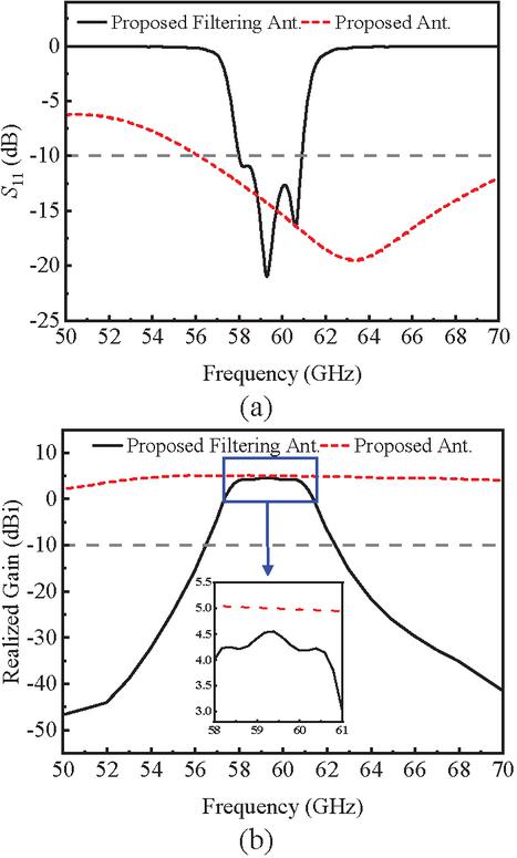
Figure 13 (a) Simulated and (b) realized gain of the proposed antenna and the proposed filtering antenna.
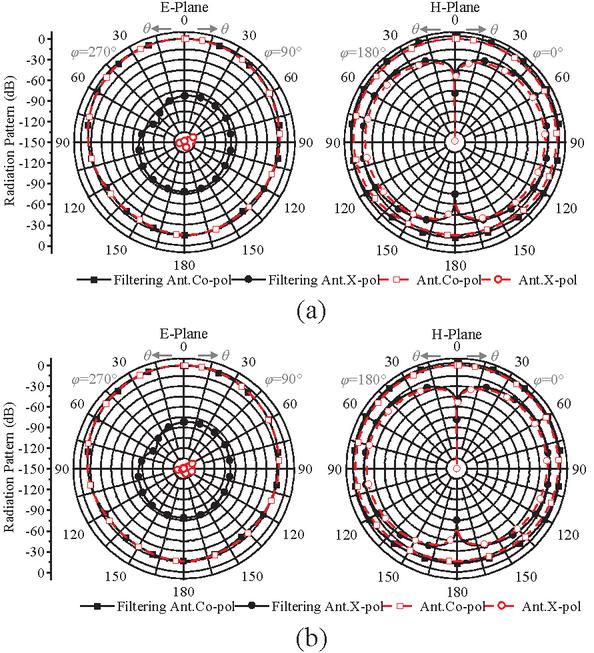
Figure 14 Comparison of simulation radiation patterns between the proposed filter antenna and the independent ME antenna: (a) E-plane and H-plane at 59 GHz. (b) E-plane and H-plane at 60 GHz.
Figure 14 quantifies radiation patterns of the proposed filtering antenna and ME antenna at operating frequencies of 59 GHz and 60 GHz. The filtering antenna exhibits little change in the H-plane pattern compared to the ME antenna, but the cross-polarization in the E-plane has increased. Specifically, the proposed filtering antenna achieves cross-polarization suppression exceeding 78 dB in the E-plane, with a half-power beamwidth (HPBW) of 77∘. The H-plane maintains cross-polarization levels below 20 dB with an extended HPBW of 170∘, indicating quasi-omnidirectional coverage capability. Furthermore, optimized design achieves consistent FBR exceeding 15 dB, effectively suppressing back-lobe radiation.
3 MEASUREMENT AND COMPARISON
3.1 Measurement
Given the constraints imposed by available fabrication and testing facilities, this study focused on the physical realization and experimental validation only of the hybrid resonator filter based on the RMCL structure, as described in section IIB. Considering that mainstream millimeter-wave measurement systems rely on planar probing platforms, the fabricated filter incorporates a broadband transition structure at its ports. This structure provides an optimized connection from the RMCL to Ground-Signal-Ground (GSG) probe pads [25], specifically designed for millimeter-wave on-wafer probing. A photograph of the final packaged device is depicted in the inset of Fig. 15.
As shown in Fig. 15, the measured results exhibit a center frequency shift of 0.7% compared to simulations, with GHz (vs. simulated 60 GHz), FBW reduction to 2.5% (vs. 3.3%), IL degradation to 2.44 dB (vs. 1.05 dB), and RL 10 dB (vs. 20 dB).
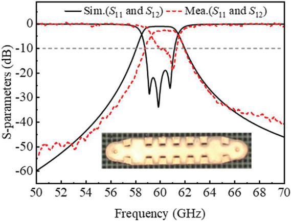
Figure 15 The simulated and measured results of the proposed filter, accompanied by the fabricated prototype (inset).
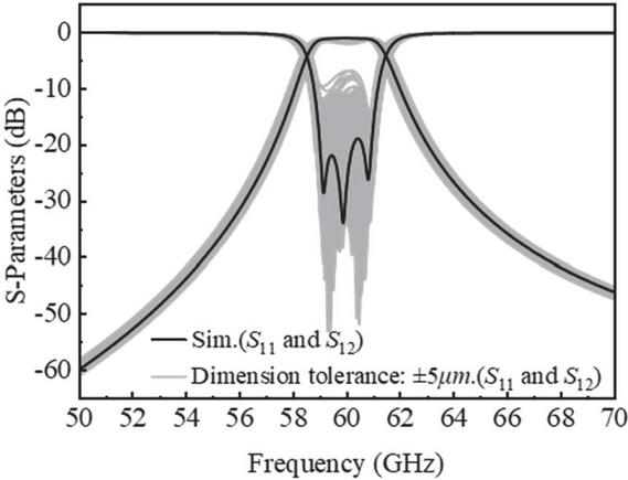
Figure 16 Sensitivity analysis of the proposed filter.
A Monte Carlo sampling (MCS) sensitivity analysis was conducted on 13 primary dimensional parameters (Fig. 16) with manufacturing tolerance limits of 5 m (the typical tolerance of the M-MAM technology [26]). Two hundred uniformly distributed random samples were simulated, excluding transition interfaces. The observed deviations between measured and simulated results are attributed to these factors: (1) critical dimension deviations exceeding 5 m tolerance; (2) unremoved dielectric material at K-inverter corners; (3) probe contact error and system calibration drift.
3.2 Comparison
As shown in Table 2, the filter antenna proposed in this paper has significant performance characteristics compared to the existing typical designs. Compared with the 3.06 dBi gain level reported in [27], the present work achieves a gain enhancement of 4.53 dBi. Although the cascaded magneto-electric dipole and hybrid resonator configuration yields lower gain than the 6.0–7.1 dBi range in [28, 29, 30], our design demonstrates three significant advancements at the demanding 59.5 GHz millimeter-wave frequency: (1) an ultra-compact vertical profile of only , (2) superior out-of-band suppression exceeding 40 dB, and (3) sharp frequency selectivity of 3.2/3.4%.
Table 2 Comparison with the previous filtering antennas
| Ref. | Impedance | Peak | Stopband Suppression | Profile | |
| Bandwidth (GHz) | Gain (dBi) | Level (dB) | (%/%) | (mm/) | |
| [27]b | 5.00–5.42 (8.0%) | 3.06 | 27 | 4.2 / 3.8 | 0.288 / 0.005 |
| [28]c | 33.7–36.3 (7.40%) | 7.10 | 13 | 2.3 / 5.4 | 0.962 / 0.112 |
| [29]b | 18.9–30.3 (46.3%) | 6.00 | 25 | 8.9 / 6.9 | 3.937 / 0.323 |
| [30]b | 24.0–28.6 (17.5%) | 6.20 | 20 | 6.1 / 10.6 | 2.330 / 0.204 |
| This Workc | 58.0–61.0 (5.04%) | 4.53 | 40 | 3.2 / 3.4 | 0.800 / 0.158 |
| aDefinition of frequency selectivity: , . and are the frequencies at the edges of the 10 dB impedance bandwidth. and are the frequencies with suppression more than 20 dB.bAll dates provided by this line are measurement dates.c All dates provided by this line are simulation dates. | |||||
4 CONCLUSION
This paper presents an innovative design of a V-band filter antenna based on RMCL, which centers on the realization of a modular split design and easy integration of a hybrid resonator filter structure and an ME dipole antenna. The antenna exhibits an impedance bandwidth of 5.04% at the center frequency of 59.5 GHz and maintains a cross-polarization level below 20 dB. The overall size of the antenna structure is optimized to mm (including the ground plane), corresponding to a profile height of only . In particular, the design exhibits excellent out-of-band suppression characteristics. Outside the frequency band of 4.8% from the center frequency, rapid gain attenuation below 10 dBi is achieved. This feature significantly reduces the risk of adjacent channel interference in V-band antenna systems, providing an effective solution for high-density integrated RF front ends.
ACKNOWLEDGMENT
This work was supported by the project of State Grid Shaanxi Electric Power Corporation Limited (5226KY250015).
References
[1] P. Smulders, “Exploiting the 60 GHz band for local wireless multimedia access: Prospects and future directions,” IEEE Commun. Mag., vol. 40, no. 1, pp. 140–147, Jan. 2002.
[2] T. S. Rappaport, S. Sun, R. Mayzus, H. Zhao, Y. Azar, K. Wang, G. N. Wong, J. K. Schulz, M. Samimi, and F. Gutierrez, “Millimeter wave mobile communications for 5G cellular: It will work!,” IEEE Access, vol. 1, pp. 335–349, 2013.
[3] D. Liu, B. Gaucher, U. Pfeiffer, and J. Grzyb, Advanced Millimeterwave Technologies: Antennas, Packaging and Circuits. Hoboken, NJ, USA: Wiley, 2009.
[4] F. Queudet, I. Pele, B. Froppier, Y. Mahe, and S. Toutain, “Integration of pass-band filters in patch antennas,” in The 32nd European Microwave Conference, pp. 685–688, 2002.
[5] Y.-F. Cao, Y. Zhang, and X.-Y. Zhang, “Filtering antennas: From innovative concepts to industrial applications,” Frontiers Inf. Technol. Electron. Eng., vol. 21, no. 1, pp. 116–127, Jan. 2020.
[6] Z. H. Jiang and D. H. Werner, “A compact, wideband circularly polarized co-designed filtering antenna and its application for wearable devices with low SAR,” IEEE Trans. Antennas Propag., vol. 63, no. 9, pp. 3808–3818, Sep. 2015.
[7] C.-X. Mao, S. Gao, Y. Wang, Q. Luo, and Q.-X. Chu, “A shared-aperture dual-band dual-polarized filtering-antenna-array with improved frequency response,” IEEE Trans. Antennas Propag., vol. 65, no. 4, pp. 1836–1844, Apr. 2017.
[8] M.-C. Tang, Y. Chen, and R. W. Ziolkowski, “Experimentally validated, planar, wideband, electrically small, monopole filtennas based on capacitively loaded loop resonators,” IEEE Trans. Antennas Propag., vol. 64, no. 8, pp. 3353–3360, Aug. 2016.
[9] C.-T. Chuang and S.-J. Chung, “New printed filtering antenna with selectivity enhancement,” in 2009 European Microwave Conference (EuMC), pp. 747–750, 2009.
[10] X. Y. Zhang, W. Duan, and Y.-M. Pan, “High-gain filtering patch antenna without extra circuit,” IEEE Trans. Antennas Propag., vol. 63, no. 12, pp. 5883–5888, Dec. 2015.
[11] H.-T. Hu and C. H. Chan, “Substrate-integrated-waveguide-fed wideband filtering antenna for millimeter-wave applications,” IEEE Trans. Antennas Propag., vol. 69, no. 12, pp. 8125–8135, Dec. 2021.
[12] X. Cheng, X. Chen, J. Liu, X. Liu, J. Li, S. Gao, and A. A. Kishk, “Compact dual-polarized low sidelobe monopulse slot antenna array based on gap waveguide technology,” IEEE Trans. Antennas Propag., vol. 73, no. 2, pp. 1215–1220, Feb. 2025.
[13] G. Q. Luo, W. Hong, H. J. Tang, J. X. Chen, X. X. Yin, and Z. Q. Kuai, “Filtenna consisting of horn antenna and substrate integrated waveguide cavity FSS,” IEEE Trans. Antennas Propag., vol. 55, no. 1, pp. 92–98, Jan. 2007.
[14] Z. Wang, S. Lin, Y. Ge, Z. Chen, J. Zhao, and J. H. Chen, “Unlock the potential of large-element-spacing arrays: A meta-lens solution for grating-lobe suppression and gain enhancement,” Electromagn. Sci., vol. 2, no. 4, 2024.
[15] S. J. Yang, Y. M. Pan, L.-Y. Shi, and X. Y. Zhang, “Millimeter-wave dual-polarized filtering antenna for 5G application,” IEEE Trans. Antennas Propag., vol. 68, no. 7, pp. 5114–5121, July 2020.
[16] X. Wen, Y. Yu, G. Shi, Z. Wang, Q. Cheng, and Y. Li, “WR-3.4 band waveguide and bandpass filters using copper additive manufacturing,” IEEE Trans. Microw. Theory Techn., vol. 71, no. 3, pp. 1190–1200, Mar. 2023.
[17] Z. Wu, G. Shi, X. Lu, R. Liang, X. Wen, J. Wang, B. Zhou, Z. Wang, C. Guo, and A. Zhang, “A W-band air-filled coaxial bandpass filter employing micro metal additive manufacturing technology,” Int. J. RF Microw. Comput.-Aided Eng., vol. 31, no. 9, pp. 1–10, Sep. 2021.
[18] R. Liang, C. Guo, Q. Yang, G. Shi, Z. Wang, and A. Zhang, “A micromachined ultra-wide stopband lowpass filter based on stepped impedance resonator loaded T-shaped structure,” Int. J. RF Microw. Comput.-Aided Eng., vol. 32, no. 12, pp. 1–7, Dec. 2022.
[19] X. Wen, H. Yang, Z. Wu, Y. Yu, G. Shi, and Z. Wang, “A 100-180-GHz coaxial frequency tripler based on copper additive manufacturing,” IEEE Trans. Microw. Theory Techn., vol. 71, no. 10, pp. 4337–4345, Oct. 2023.
[20] H. Zhou, N. A. Sutton, and D. S. Filipovic, “Surface micromachined millimeter-wave log-periodic dipole array antennas,” IEEE Trans. Antennas Propag., vol. 60, no. 10, pp. 4573–4581, Oct. 2012.
[21] Y. Saito, M. V. Lukic, D. Fontaine, J.-M. Rollin, and D. S. Filipovic, “Monolithically integrated corporate-fed cavity-backed antennas,” IEEE Trans. Antennas Propag., vol. 57, no. 9, pp. 2583–2590, Sep. 2009.
[22] J. M. Oliver, J.-M. Rollin, K. Vanhille, and S. Raman, “A W-band micromachined 3-D cavity-backed patch antenna array with integrated diode detector,” IEEE Trans. Microw. Theory Techn., vol. 60, no. 2, pp. 284–292, Feb. 2012.
[23] J. S. Hong and M.J. Lancaster, “Microstrip filters for RF/microwave applications,” IEEE Microw. Mag., vol. 3, no. 3, pp. 62–65, Nov. 2002.
[24] X. Zhong, Q. Li, C. Guo, J. Li, Z. Wang, J. Shi, X. Chen, and A. Zhang, “A D-band wideband magnetoelectric dipole antenna array based on micro-metal additive manufacturing,” IEEE Trans. Antennas Propag., vol. 72, no. 8, pp. 6500–6509, Aug. 2024.
[25] Q. Yuan, T. Sun, B. Tang, Z. Wang, G. Shi, C. Guo, and A. Zhang, “A non-50-RMCL transition designed for on-chip measurement in the 0-170 GHz frequency range,” IET Microwaves, Antennas & Propagation, vol. 17, no. 11, pp. 857–862, Aug. 2023.
[26] Q. Yang, H. Yi, J. Sheng, J. Xu, Q. Zhang, and Z. Cao, “An H-plane high-flatness ridge waveguide dual-directional coupler based on copper additive manufacturing,” IEEE Microw. Wireless Technol. Lett., vol. 34, no. 7, pp. 879–882, July 2024.
[27] S. Yan, C. Zhang, Q. Chen, and M. Tong, “A novel compact filtering antenna for 5.0-GHz WLAN communication system,” Applied Computational Electromagnetics Society (ACES) Journal, vol. 37, no. 09, pp. 996–1004, Sep. 2022.
[28] P. Jia, C. Xing, X. Jiang, and Y. Shi, “A Ka-band microstrip millimeter-wave filter antenna fed by ridge gap waveguide,” in Proc. Int. Conf. Microw. Millim. Wave Technol. (ICMMT), pp. 1–3, May 2024.
[29] Y. Z. Tian, Y. M. Pan, X. Y. Liu, and K. W. Leung, “An SIW-based wideband endfire filtering magneto-electric dipole antenna for millimeter-wave applications,” IEEE Trans. Antennas Propag., vol. 71, no. 12, pp. 9986–9991, Dec. 2023.
[30] Y. Gong, X.-L. Yang, and X.-W. Zhu, “Millimeter-wave filtering antenna and array with multiple flexible radiation nulls based on hybrid coupling of SIW cavities and split-ring slots,” IEEE Antennas Wireless Propag. Lett., vol. 24, no. 4, pp. 823–827, Apr. 2025.
Biographies

Nan Wang received his M.Sc. degree in electromagnetic and microwave technology from Xidian University, Xi’an, China, in 2010. His current research interests include the research of operation and maintenance technology of power transmission and transformation equipment.

Ying Zhu was born in Xi’an, China, in 1999. She received the B.Eng. degree in information engineering from Xi’an Jiaotong University, Xi’an, in 2021, where she is currently pursuing the master’s degree in electromagnetic field and microwave technology. Her research interests include the design of microwave passive components.

Jing Wang received her master’s degree in software engineering from Xi’an Jiaotong University, Xi’an, China, in 2012. Her research interests include digital technology management and application.

Xinjiang Liu obtained a master’s degree in electronic and communication engineering from the University of Chinese Academy of Sciences, China, in 2020. His current research interests include trustworthy artificial intelligence and advanced communication technologies.

Chaoyu Feng graduated with a bachelor’s degree from Huazhong University of Science and Technology, China, in 2014, majoring in electrical engineering and its automation. He obtained his master’s degree from North China Electric Power University in 2020,majoring in control engineering. His current research interests include the maintenance and overhaul of transmission lines.

Xinzhan Cai obtained a master’s degree in Electronic Science and Technology Engineering from Nankai University, China, in 2022. His current research interests include the application technology of power communication and artificial intelligence in the power grid field.

Xiaolan Zhang received her M.Eng. degree in electrical machines and apparatuses from Xi’an Jiaotong University, Xi’an, China, in 2014. Her main research directions include the detection and analysis of switchgear equipment, and the research on auxiliary monitoring systems for smart substations.

Xuefeng Zhao received her Ph.D. degree in electrical engineering from Xi’an Jiaotong University, Xi’an, China, in 2011. Her current research interests include the research of power cable test technology and fault diagnosis.

Wensen Wang received his MSc degree in electrical engineering from Xi’an Jiaotong University, Xi’an, China, in 2016. His current research interests include the research of intelligent operation inspection of power equipment and high voltage engineering.

Guang Dai received his B.Eng. degree in mechanical engineering from Dalian University of Technology, China, and M.Phil. degree in computer science from the Zhejiang University and the Hong Kong University of Science and Technology. He is currently a senior research scientist at State Grid Corporation of China, and also the founder of SGIT AI Lab, State Grid Corporation of China. His main research interests include Bayesian statistics, deep learning, reinforcement learning, optimization computation, and related applications.

Jiawei Yang graduated from the department of electronics and communications engineering of North China Electric Power University, BaoDing, China, in 2023. He is currently involved in the research of new communication technology applications and Beidou communications.
ACES JOURNAL, Vol. 41, No. 2, 170–179
DOI: 10.13052/2026.ACES.J.410208
© 2026 River Publishers