Frequency-Selective Polarization Converter with Ultra-Wideband Linear-to-Circular Conversion and High Selectivity Based on Stair-Case Shape
Kun Liao1*, Jie Shu2, Ruquan Wen1, Renxia Ning3, and Zhiming Liu2
1School of Mechanical and Electronic Engineering Pingxiang University, Pingxiang 337055, China
21010052@pxu.edu.cn, 1282479687@qq.com
2School of Information Engineering Nanchang University, Nanchang 330031, China
2768177455@qq.com, lzmedu@foxmail.com
3School of Information Engineering Huangshan University, Huangshan 245041, China
nrxxiner@163.com
*Corresponding author
Submitted On: July 08, 2025 Accepted On: June 15, 2026
ABSTRACT
In this paper, an ultra-wideband and high-selectivity reflective polarization converter is presented, which is based on a simple stair-case shape. The simulation results indicate that the polarization converter achieves ultra-wideband linear-to-circular polarization conversion under linearly polarized incident wave. Its 3 dB axial ratio frequency band is 5.47–16.15 GHz, and its relative bandwidth is 98.8%; besides, linear-to-linear polarization conversion is realized on both sides of the circular polarization band from 4.57 to 5.30 GHz and 16.28 to 18.11 GHz when dB. Therefore, multiple polarization functions are realized using a single simple structure. Moreover, the physical mechanism and surface current distributions of the polarization converter are analyzed. In addition, the sample is processed and tested, verifying the feasibility of our idea.
Keywords: Reflective polarization converter, staircase shape, tri-modal polarization conversion..
1 INTRODUCTION
Polarization is a basic characteristic of electromagnetic waves, and controlling polarization is of great significance in many application fields such as wireless communications, microwave radar, and optics [1, 2, 3]. The emergence of metasurfaces provide the new ideas for controlling the polarization of electromagnetic waves, and polarization converters based on metasurface have the characteristics of compact structure, low profile, and easier integration compared with traditional converters [4, 5, 6]. Therefore, the works of polarization control are investigated in depth based on metasurface polarization converters [7, 8, 9]. Among them, the main types of polarization control are linear-to-linear (LTL), linear-to-circular (LTC) and circular-to-circular (CTC) [10, 11, 12], for example, a triple-arrow resonant structure [13], which realizes the conversion from linear-polarized to cross-polarized in the range of 8.0–18.5 GHz. Reference [14] proposed a double V-shaped metasurface polarization converter to generate a broadband cross-polarized reflection band from 12.4 to 27.96 GHz. A metasurface polarization converter consists of an inner cross structure and outer double C-shaped ring was designed in [15], realizing the dual-band cross-polarized in the ranges of 9.38 to 13.36 GHz and 14.84 to 20.36 GHz. Zheng et al. presented a reflective polarization converter with two meander-lines and one metal-strip structure, which realizes low-frequency cross-polarized (fractional bandwidth of 59.6%) and high-frequency circular polarization conversion (fractional bandwidth of 13.0%) at linear-polarized incidence [16]. In addition, the transition band between two polarization bands has a bandwidth of 12.6%. A composite metasurface with metal strip and rectangular ring was proposed by Huang [17]. Results show that the cross-polarization conversion is achieved in two frequency bands. In our previous work, we designed a polarization converter based on inner cross structure and outer two pairs of serpentine lines structure to achieve polarization conversion in three frequency bands [9]. Based on the existing works, it is not difficult to find that metasurface polarization converters are easier to achieve linearly polarized than circularly polarized, and circular polarization conversion is difficult to achieve ultra-wideband control. Furthermore, the design method of using multi-structures to achieve multi-bands polarization control needs to be changed. Therefore, designing a single structure metasurface polarization converter to achieve multi-bands multi-polarization control is a great challenge.
A reflective polarization converter based on a single meander line ring is proposed in this paper, which achieves ultra-wideband LTC polarization conversion and cross polarization conversion on both sides of the circular polarization band. The innovations of this paper are as follows. A single structure polarization converter achieves three-frequency bands and two polarization controls, which is an advantage that the existing works do not have. The different polarization control frequency bands have high-selectivity for electromagnetic waves. In addition, the experiment results demonstrate the simulation data, and verify the feasibility of the design idea.
2 STRUCTURAL SIMULATION AND THEORETICAL ANALYSIS
2.1 Structural simulation
A schematic diagram of the unit cell for our polarization converter is represented in Fig. 1. The unit cell consists of a dielectric substrate F4BM220 (, ) covered with a single stair-case shape metal structure and metal backplate, separated by an air layer of thickness mm. The single stair-case shape is placed at an angle of 135∘ with respect to the horizontal. Physical parameters of the single stair-case shape are defined as mm, mm, mm, mm. Full-wave simulation software CST Microwave Studio is used to simulate the designed structure.
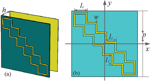
Figure 1 Layout of the unit cell: (a) stereoscopic view and (b) front view.
Since a single stair-case shape is symmetrical about an oblique direction of 135∘, the -polarized incident wave is taken as the example. The reflection coefficients of the co- and cross-polarization are and , respectively. The phase difference between co- and cross-polarization reflection coefficients is . Polarization conversion ratio (PCR) and energy conversion ratio (ECR) are defined as and . Subsequently we simulated the reflection coefficients and phase difference of the polarization converter, as shown in Fig. 2.
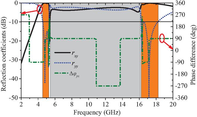
Figure 2 Simulation results of reflection coefficients and phase difference.
Figure 2 describes that co- and cross-polarization reflection coefficients are almost equivalent in the gray areas, and phase difference is almost equal to 90∘ (the phase difference in some areas is 270∘, which is also 90∘). Hence, according to the standard of circularly polarized waves, the reflected waves in the gray areas are a left-handed circularly polarized wave. In addition, the cross-polarized reflection happened in the range of 4.57 to 5.30 GHz and 16.28 to 18.11 GHz when dB in the two orange areas. Therefore, the designed polarization converter completes the polarization conversion in three-frequency bands using a single structure, which is one of the advantages of this work. Taking into account different incidence angles of the y-polarized wave, the simulation results were not satisfactory. The reason is that the increase in incident angle destroys polarization stability and leads to separation of polarization wave responses. High-order modes and gate lobes are excited in the high frequency band, resulting in impedance mismatch. Eventually, the electromagnetic characteristics significantly deteriorated, and the curve showed multiple peaks, depressions, and other phenomena. Therefore, this paper does not include an analysis of the incidence angles of the y-polarized wave.
Physical size values in the model are optimized during the design process. Changing any size can cause performance to deviate from intended goals. Therefore, only the final parameter values are given. Further, the results of PCR and ECR are calculated as described in Fig. 3.
According to Fig. 3, ECR is higher than 0.8 in three areas. Moreover, PCR has exceeded 0.9 in the range 4.57 to 5.30 GHz and 16.28 to 18.11 GHz, indicating that the polarization converter has high polarization efficiency.
Electromagnetic waves can be considered as circularly polarized waves when the axial ratio (AR) of the electromagnetic wave is less than 3.0 dB in practical engineering application. Equation (1) is used to calculate the AR of the reflected electromagnetic waves to determine the bandwidth of circular polarization.
| (1) |
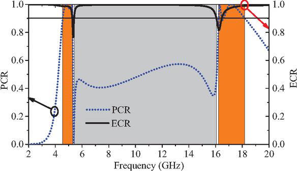
Figure 3 Calculation results of PCR and ECR.
where . Figure 4 plots the calculation results of AR.
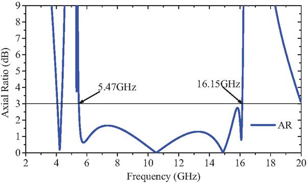
Figure 4 AR vs frequency.
It can be seen from Fig. 4 that AR of the electromagnetic waves is within 3 dB in the frequency range 5.47–16.15 GHz, and relative bandwidth is 98.7%. Combined with the results in Fig. 2, the transition bands of the cross polarization and circular polarization bands are 5.30 to 5.47 GHz and 16.15 to 16.28 GHz, and the relative bandwidths corresponding to 3.1% and 0.8%, respectively. This illustrates that the designed polarization converter has high-selectivity for electromagnetic waves, which is very important in many applications. This is another advantage of this work.
2.2 Theoretical analysis
In order to deeply grasp the working mechanism of the polarization converter, a new coordinate system (uov) with - and -axis is defined. The coordinate axes are perpendicular to each other and deviate from the -axis, as represented in Fig. 5.
According to the vector nature of the electric field, it can be decomposed into two component electric fields that are perpendicular to each other and have equal amplitude. Therefore, incident and reflected electric fields can be expressed as:
| (2) | ||
| (3) |
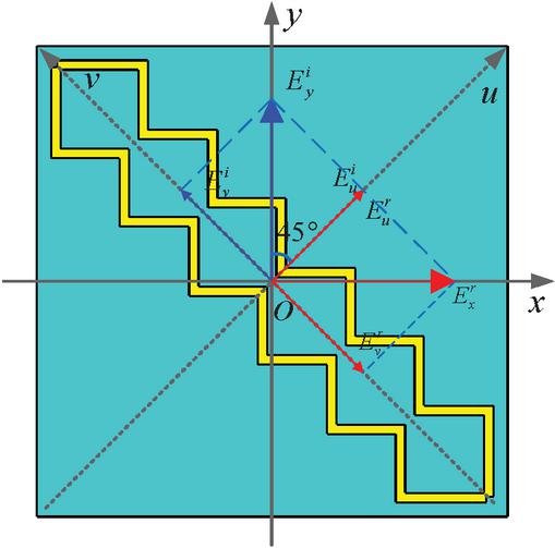
Figure 5 New coordinate system and electric field decomposition.
where and represent the unit vector in the direction of the - and -axis, and and are regarded as the amplitude of co-polarized reflected wave under the - and -polarized incoming wave, respectively. In addition, the phase relationship of the co-polarized reflection coefficients and is: . Hence, equation (3) can be written as:
| (4) |
Since the motion trajectory of the reflected electric fields vector is perpendicular to the propagation direction, the and components satisfy the following relationship:
| (5) |
From the electric field decomposition in Fig. 5, , , consequently, equation (5) can be described as:
| (6) |
The and components of the reflected electric fields in equation (6) are:
| (7) |
Therefore, the reflection coefficients of co- and cross-polarization can be obtained from equation (7) as:
| (8) |
According to equation (8), the co- and cross-polarization reflection coefficients are , when , and there is no polarization conversion. When , the co- and cross-polarization reflection coefficients are , and it has achieved a 90∘ linear polarization conversion.
However, the reflected wave is an elliptically polarized wave when or . Hence, AR of the elliptically polarized wave can be written as:
| (9) |
When , then , and the linear polarization is converted to circular polarization. Based on the above research conclusions, the -parameters at - and -polarized incidence are simulated, as depicted in Fig. 6.
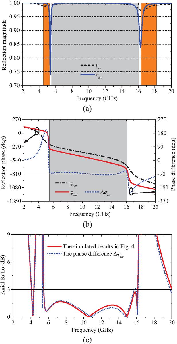
Figure 6 (a) Refection magnitude of - and -polarized incoming wave, (b) reflection phase and phase differences, and (c) AR of the reflected wave.
As can be seen from Figs. 6 (a) and (b), the co-polarized reflection coefficients are basically identical under - and -polarized incident waves in the three frequency bands of 4.57–5.30 GHz, 5.47–16.15 GHz, and 16.28–18.11 GHz. Additionally, the co-polarized reflection phase difference is approximately 90∘ in the frequency range 5.47–16.15 GHz. According to the above theory, the circularly-polarized waves are realized in this frequency band. Finally, the AR values of equations (1) and (9) are calculated. From Fig. 6 (c), it can be seen that the AR values of the two paths are equal.
Furthermore, the surface current distributions of the polarization at different frequency points is analyzed to explain its working mechanism, as displayed in Fig. 7. Note that the induced current is distributed in different positions on the stair-case shape structure at different frequency points, and the current path length is different, which shows that this structure can achieve different polarization functions.
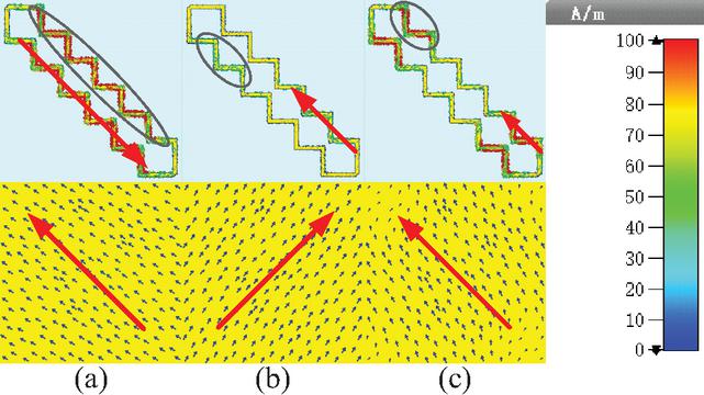
Figure 7 Surface current distributions of upper and lower metal layers at frequency points (a) 5.0 GHz, (b) 11.0 GHz, and (c) 18.0 GHz.
In Fig. 7 (a), the induced current path length at this frequency point occupies most of the structure, which conforms to the principle of long current path and low resonance frequency point. In addition, the surface currents of the upper and lower metal layers are in opposite directions, forming a closed current loop and generating magnetic resonance, thus realizing cross-polarization conversion. At 11.0 GHz, the direction of the induced current in the upper and lower metal layers is perpendicular, indicating that the reflected wave is a circularly polarized wave. As can be seen in Fig. 7 (c), the induced current is concentrated on a short structural path, and the current directions of the upper and lower layers are in the same direction, which also achieves a 90∘ polarization conversion.
Table 1 Comparison with existing related articles
| Ref. | Structural Diversity | Polarization Diversity | High-Selectivity | Polarization Bandwidth |
| [3] | Two | One | NO | 49.1% |
| [18] | One | One | NO | 91.2% |
| [9] | three | two | NO | 82.2% |
| [15] | Two | One | NO | 66.3% |
| [19] | Two | One | NO | 31.7% |
| This Work | One | Two | 3.1%, 0.8% | 124.2% |
3 PROCESSING AND MEASUREMENT
In order to demonstrate the conversion performance of the designed ultra-wideband polarization converter, the proposed polarization converter was fabricated and tested. The processed sample consists of units with a size of mm, as depicted in Fig. 8 (a). The metal structure is printed on a F4B dielectric substrate with relative dielectric constant of 2.2 using PCB printing technology, and the substrate thickness is 0.25 mm. Plastic nylon columns are used to support the whole structure. Figure 8 (b) shows the sample testing in a microwave darkroom environment. The sample is surrounded with absorbing materials to avoid diffraction interference of electromagnetic waves. The measurement equipment consists of a vector network analyzer and two standard broadband linearly polarized horns – one horn serving as a transmitting antenna and the other as a receiving antenna. Figure 8 (c) plots the test and simulation results of the designed polarization converter sample at vertical incidence.
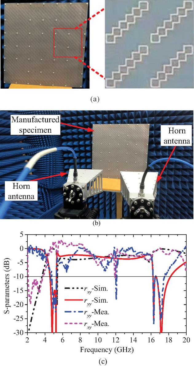
Figure 8 (a) Fabricated sample, (b) measurement environment of the sample, and (c) measurement and simulation results at vertical incidence.
It is not difficult to see from the results in Fig. 8 (c) that the experimental results are in good agreement with the simulation results, further demonstrating the feasibility and reliability of the design. Small deviations are allowed, taking into account factors such as machining accuracy, measurement tolerances, and background noise. In order to highlight the advantages of this work, the characteristics of existing related articles are listed in Table 1.
According to Table 1, compared with existing polarization converters, the designed polarization converter has the characteristics of a single structure, multiple polarization modes and broadband operating bandwidth.
4 CONCLUSIONS
A metasurface polarization converter with a single structure is reported and has cross polarization – circular polarization – cross polarization frequency response characteristics. The simulation results denote that the LTC polarization conversion is realized in the range of 5.47–16.15 GHz (relative bandwidth of 98.8%). Furthermore, the relative transition bandwidths between linear polarization and circular polarization bands are 3.1% and 0.8%, respectively, indicating that the polarization converter has strong frequency selectivity. Theoretical analysis and experimental testing have demonstrated the reliability of the idea. So far, the polarization converter provides a certain theoretical foundation for multi-polarization control and polarized antenna design.
ACKNOWLEDGMENT
This work was supported by the National Natural Science Foundation of China (Grant No. 62201240, 62571224), the Natural Science Foundation of Jiangxi Province (Grant No. 2022BAB212005), the open research project of Engineering Research Center of Power Integrated Circuit AnHui Province (NO. ERCPZX202404), the Aeronautical Science Foundation of China (Grant No. 20230020052003, 20230000052035, 20230018052002).
REFERENCES
[1] A. K. Fahad, C. Ruan, R. Nazir, and B. Hassan, “Transmissive polarizer metasurfaces: From microwave to optical regimes,” Nanomaterials, vol. 12, no. 10, p. 1705, 2022.
[2] S. Jorwal, A. Dubey, R. Gupta, and S. Agarwal, “A review: Advancement in metamaterial-based RF and microwave absorbers,” Sensors and Actuators A: Physical, vol. 354, p. 114283, 2023.
[3] B. Hayat, J. Zhang, A. Majeed, M. Ishfaq, A. Khan, and S. Ahmad, “A low profile wideband linear to circular polarization converter metasurface with wide axial ratio and high ellipticity,” Electronics, vol. 13, no. 2, p. 352, 2024.
[4] S. C. Jiang, X. Xiong, and Y. S. Hu, “Controlling the polarization state of light with a dispersion-free metastructure,” Physical Review X, vol. 4, no. 2, p. 021026, 2014.
[5] Y. Zhao and A. Alù, “Manipulating light polarization with ultrathin plasmonic metasurfaces,” Physical Review B, vol. 84, no. 20, p. 205428, 2015.
[6] G. Deng and Z. Kou, “Electrically controllable broadband reflective linear cross-polarization conversion based on liquid crystals,” Optics Express, vol. 31, no. 17, pp. 27420–27432, 2023.
[7] X. Yuan, J. Chen, and J. Wu, “Graphene-based tunable linear and linear-to-circular polarization converters in the THz band,” Results in Physics, vol. 37, p. 105571, 2022.
[8] X. Song, H. Lu, and S. Yang, “Ultra-wideband frequency selective surface with metal gratings for polarization conversion under arbitrary polarized angles,” Applied Computational Electromagnetics Society (ACES) Journal, vol. 40, no. 10, pp. 1002–1009, 2025.
[9] K. Liao and S. Liu, “A polarization converter with single-band linear-to-linear and dual-band linear-to-circular based on single-layer reflective metasurface,” International Journal of RF and Microwave Computer-Aided Engineering, vol. 32, no. 2, p. e22955, 2022.
[10] A. Ahmed, Q. Cao, and M. I. Khan, “An ultra-thin multifunctional chiral metasurface with asymmetric transmission, cross-polarization conversion, and circular dichroism for Ku- and K-band applications,” Journal of Physics D: Applied Physics, vol. 57, no. 3, p. 035001, 2023.
[11] Z. Cui, Z. Xiao, and M. Chen, “A transmissive linear polarization and circular polarization cross polarization converter based on all-dielectric metasurface,” Journal of Electronic Materials, vol. 50, no. 7, pp. 4207–4214, 2021.
[12] N. Pouyanfar, J. Nourinia, and C. Ghobadi, “Low-profile reflective surface for multi-band linear-to-linear and linear-to-circular polarization conversion,” IEEE Access, vol. 11, pp. 135159–135165, 2023.
[13] A. Rashid, M. Murtaza, and S. A. A. Zaidi, “A single-layer, wideband and angularly stable metasurface based polarization converter for linear-to-linear cross-polarization conversion,” PLoS ONE, vol. 18, no. 1, p. e0280469, 2023.
[14] X. Gao, X. Han, and W. P. Cao, “Ultrawideband and high-efficiency linear polarization converter based on double V-shaped metasurface,” IEEE Trans. Antennas Propag., vol. 63, no. 8, pp. 3522–3530, 2015.
[15] C. Fu, Z. Sun, and L. Han, “Dual-bandwidth linear polarization converter based on anisotropic metasurface,” IEEE Photon. J., vol. 12, no. 2, pp. 1–11, 2020.
[16] Q. Zheng, C. Guo, and J. Ding, “Wideband metasurface-based reflective polarization converter for linear-to-linear and linear-to-circular polarization conversion,” IEEE Antennas Wireless Propag. Lett., vol. 17, no. 8, pp. 1459–1463, 2018.
[17] X. Huang, H. Yang, D. Zhang, and Y. Luo, “Ultrathin dual-band metasurface polarization converter,” IEEE Trans. Antennas Propag., vol. 67, no. 7, pp. 4636–4641, 2019.
[18] J. L. Wu and B. Q. Lin, “Ultra-wideband reflective polarization converter based on anisotropic metasurface,” Chinese Physics B, vol. 25, no. 8, p. 088101, 2016.
[19] A. Undrasi, D. Kundu, and K. K. Kamalesh, “A closely spaced dual-band dual-sense linear-to-circular polarization converter for X-band applications,” Optik-International Journal for Light and Electron Optics, vol. 320, p. 172135, 2025.
BIOGRAPHIES

Kun Liao received the Ph.D. degree in communication and information systems from Nanjing University of Aeronautics and Astronautics (NUAA), China, in 2023. He became a lecturer in Pingxiang University in 2024. His main research interests include antenna design, frequency selective surfaces and metasurfaces.

Jie Shu, born in 2004, is currently pursuing his Bachelor of Engineering degree in Communication Engineering at Nanchang University, China. His research interests include microwave filter design and antenna design.

Ruquan Wen, born in 1981, received a B.S. degree from Hunan University of Science and Technology, China, in 2004 and an M.S. degree from Lanzhou University of Technology in 2009. Her current research interests include signal processing and superconducting materials.

Renxia Ning, received a M.S. degree from Anhui University, China, in 2009. Her main research interests include metamaterials, terahertz, and micro-nano sensing devices, analog driver integrated circuits, and miniaturized RF antenna design.

Zhiming Liu, born in 1989, received a B.S degree from East China University of Technology, China, in 2012, a M.S. degree from Nanchang University in 2015, and a Ph.D. degree from Nanjing University of Aeronautics and Astronautics in 2019. His current research interests include electromagnetic metamaterial device design and application, microwave component and system design, and antenna design.
ACES JOURNAL, Vol. 41, No. 7, 697–703
DOI: 10.13052/2026.ACES.J.410710
© 2026 River Publishers