A Substrate-Loaded Gain-Enhanced Vivaldi Antenna Design for the SolidState High-Power Microwave Module
Zichong Chen, Fangsheng Cai, Peng Bai, Taijing Shi, Xiaojun Mao, and Yun Jiang*
Department of Microwave Research Hunan Vanguard Group Co. Ltd., Changsha 410137, China czc0720@hnu.edu.cn, cfsnuaa@163.com, 2641630277@qq.com, shitaijing@yeah.net, 804367142@qq.com, 867581306@qq.com
∗Corresponding Author
Submitted On: July 18, 2025; Accepted On: April 08, 2026
ABSTRACT
This paper presents an evolutionary design process, fabrication, and verification of a substrateloaded Vivaldi antenna (VA) design for the pulse-type high-power microwave (HPM) solid-state T/R module. The antenna design utilizes a substrate with high permittivity to improve its power handling capacity (PHC), a snowflake-like metasurface (SFL-MS) lens on the front of the VA to enhance the directivity and impedance characteristics in the middle and high frequency bands, and rectangular slits on the radiating brims of the VA for further broadening its bandwidth and realized gain at low frequencies. After HPM measurement, these functional methods are proven to be effective for jointly contributing to optimizing antenna performances. The proposed prototype shows an operating band of 2.28–6.54 GHz (voltage standing wave ratio [VSWR] 2) and the PHC values are over 8000 W in this band. The measured realized gain and the maximum gain enhancement can reach 6.56–8.15 dBi and 5.96 dBi. The measured results are reasonable and agree well with simulations.
Keywords: High-power microwave, metasurface lens, realize gain enhancement, Vivaldi antenna..
1 INTRODUCTION
High-power microwave (HPM) technology plays an important role in terms of the electronic component and system, its protective technology, weapon and equipment, and biological effect. Different from the vacuum-state HPM source, the solid-state HPM output module, made of gallium nitride (GaN) material, has advantages of light weight, parameterized flexibility, and using a coaxial port to feed instead of a waveguide port. Currently, the maximum stable power output from one port on the solid-state HPM module is not more than 8000 W in the S- and C-band in practical engineering uses, so that hundreds of such solid-state HPM modules can realize an equivalent effect like the vacuum-state HPM system. As the element of the phased array, they are tested for high directivity in a wide band in order to realize wide-beam scanning.
For the virtues of stable realized gain in broadband and compact structures, efforts have been made into Vivaldi antennas (VAs) since it was proposed in the 1970s [1, 2]. However, VA loaded on the common substrate () is seldom adopted in the HPM system for its low power handling capacity (PHC), usually 1000–3000 W in the air. One way to improve the PHC of the VA is making the antenna all-metallic. Researchers devote energy into all-metallic VA elements [3, 4] and arrays [5, 6, 7, 8]. Even though the allmetal antenna satisfies the PHC demand of the HPM system, it is obviously overweight compared to the substrate-loaded antenna, especially when arranging arrays, which will no doubt restrict the flexibility and mobility of the solid-state HPM system on moving platforms.
Another solution is to adopt VAs on the dielectric substrate with high permittivity, which evidently decreases the value of maximum -field distribution in the operating band [9, 10, 11], and successfully enhances the PHC of the antenna. The VA on the high permittivity substrate will introduce a high radiation loss, however, which will lead to lowering the radiation efficiency and directivity of the VA. It is an important scientific research direction to improve the realized gain and directivity of the VA on the substrate.
A single-layered array consisting of two fourelement VA is fabricated and verified for gain enhancement in the microwave band [12]. Adding metasurface (MS) to antennas is considered effective for gain enhancement in the VA design. Designing an MS element with various shapes and arrangements on the front of the substrate between two radiating brims, an improving gain can be obtained in the IoT/WLAN band [13], 5G mmWave application [14, 15], frequency point [16], and UWB [17, 18, 19, 20] in the microwave band. Based on the MS design, introducing novel structures to the VA can further help gain enhancement. Expanding the front part of the substrate to rectangle [21], ellipse [22, 23] or cone [24] can at most increase 4.8 dBi, 5.5 dBi, 2 dBi, and 6.35 dBi, respectively. Besides, elliptical director [25, 26], spoof surface plasmon polariton structure [27], and cascaded cavity-based substrate cut-out technique [28] are also greatly helpful for gain-enhancement of the VA.
In this paper, we present the design, iteration, fabrication, and experimental verification of an HPM VA using a PCB substrate with high permittivity. The proposed antenna design can cover a voltage standing wave ratio (VSWR) below 2 in a band of 2.28–6.54 GHz, where PHC values are over 8000 W and a gain enhancement of 0.66–5.96 dBi is obtained, showing its practical potential in the pulse-type HPM system. The evolution process of the proposed antenna can be concluded as follows:
Step 1. The conventional VA is loaded on the substrate with high permittivity to improve the PHC so that the antenna can be applied in the HPM system.
Step 2. In order to further offset the gain loss, a snowflake-like (SFL) unit cell is proposed, and an expansion of the substrate is added on the opening of the exponential curve. Proposed unit cells are designed in numbers and arrangement as a snowflake-like metasurface (SFL-MS) lens embedded on the expanded substrate as an MS lens, which focalizes the electromagnetics to improve the directivity and radiation efficiency.
Step 3. Adding rectangular slits on two brims of the VA, which mitigates the diffracted current, thus broadening the operating band of the VA and further compensating its realized gain in the low-frequency band.
2 ANTENNA DESIGN
2.1 Ant I and Ant II
The evolution process of the proposed design in this paper is shown in Fig. 1, where the original antenna, Ant I, is a VA on an FR-4 substrate (, ). The exponential function of the VA is . A gradient microstrip line and a sector balun are employed to improve the impedance match. According to the calculating method of PHC at a certain frequency point:
| (1) |
where input power is 0.5 W, breakdown -field intensity in the air is , and is the maximum -field distribution of the target antenna. From equation (1), it is evident that lowering the value of is helpful to increase PHC. The polarization ability of electric charge in the -field is proportional to the permittivity. In other words, the higher the permittivity, the lower the intensity of the -field distribution. Though the PHC of the antenna on a substrate with high permittivity is greatly improved, the radiation efficiency will be much limited, which leads to a discount effect in the HPM application. After comprehensive consideration among the PHC, realized gain, and fabricated cost, in this design, a substrate named TP-1020 () of thickness 1.35 mm is employed to substitute the previous one as Ant II. Not only is the PHC promotion of the Ant II taken into consideration, but acceptable realized gain and fabricated cost are obtained at the same time.
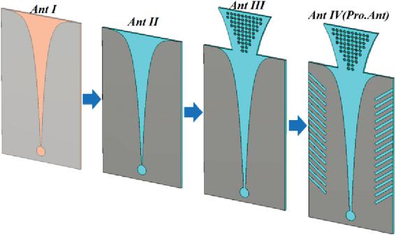
Figure 1 Evolution process of the antenna design.
It is presented as simulated PHC between the VA on the FR-4 and TP-1020 substrate in Fig. 2 (a). The PHC of the VA on the FR-4 substrate is 20–50% of that on the TP-1020 substrate. Enhancing the PHC of the VA, the substrate with high permittivity also brings loss to the antenna radiation. Simulated VSWR and realized gain are shown in Figs. 2 (b) and (c), where a deterioration of impedance match and a decrease of 0.6–1.6 dBi realized gain are observed.

Figure 2 Comparison of simulated results between Ant I and Ant II (a) PHC, (b) VSWR, and (c) realized gain.
2.2 Snowflake-like unit
MS lens constraints electromagnetics and extends its path on the aperture of the VA design. The extension of the propagating path in the MS lens change the electromagnetic phase of the VA, making full use of energy, so that the beam radiates more concentratedly in the end-fire direction. The aim is to realize a transition from a spherical wave compensated by units on different positions () in MS lens to the plane wave:
| (2) |
where is wave number in free space and is focal distance.
The core idea of the equivalent medium theory is to simplify MS into a plate of uniform material and isotropic properties. What we ultimately aim to find are the equivalent constitutive parameters that describe this virtual thin plate. According to the transmission theory, equivalent impedance , refractive index , dielectric constant, and permeability can be calculated with and :
| (3) | |
| (4) | |
| (5) | |
| (6) |
According to the theory of MS lens described in Fig. 3, the principle of the EM wave propagating through two interfaces can be expressed as:
| (7) |
where and represent refractive index and angle, respectively. According to equation (7), and are constant values. To enhance the realized gain for the antenna, the radiated beam should be as accumulated as possible, which means is bigger than , and thus of the MS lens design should be minimized as much as possible. It is very suitable to add an MS lens into the Ant II model, for there is huge potential in creating a huge refractive difference between the TP-1020 substrate and the MS lens. Therefore, an MS lens with a low refractive index is expected to be constructed to enhance the realized gain of the VA. First of all, a MS lens consisting of SFL unit cells is proposed with a combination of a rectangular strip and its two copies rotating by its geometric center, respectively. Next, the proposed SFL unit cell is set with boundary conditions to extract the electromagnetic parameters of the MHL unit. According to the overall proposed antenna model, the electromagnetic wave propagates along the axis, which is set to an open boundary. The perfect electrical boundary and the perfect magnetic boundary are set perpendicular to the and directions, respectively.

Figure 3 Schematic diagram of electromagnetic wave propagation at the interface between the air and SFL-MS lens.
According to the relevant theory, the cell size should be no more than . As is simulated in Figs. 4 (a) and (b), there are absent sharp resonances for S-parameter and extracted parameter curves existing over the target frequency range, which reveals that the proposed SFLMS is not resonant in this frequency range. The transmission coefficient is close to 0, which indicates that radiation losses caused by the proposed SFL-MS can be ignored. The equivalent impedance , refractive index , epsilon_r, and are 0.7, 2.46, 3.48, and 1.65 over the non-resonant frequency band, which is much smaller than that of the imprinted substrate. Such a difference in relative permittivity between the substrate and MS lens is expected to enhance the realized gain of the antenna over a wide band.

Figure 4 Simulated results of SFL-MS unit (a) reflection and transmission and (b) extracted properties.
2.3 Ant III
The MS lens proposed in this paper is inverted trapezoidal including 10 rows of SFL units, where equal units in quantity are arranged in two adjacent rows: 10 units are put in the top two rows, and there are two units cut when every two rows descend. In the bottom two rows, there are four SFL units on the extra substrate. The substrate is expanded on the opening of two exponential curves, and the MS is added on it. Considering the influence of the position of the lens on the antenna size and radiation characteristic, the model with optimum results is regarded as Ant III. In order to reduce the size and weight of the expanded substrate, two curves of its brim are exponential. In Fig. 5 (a), the impedance match of Ant III is improved, and its VSWR below 2 covers 3.5–6.68 GHz. Comparisons of realized gain between Ant II and Ant III are shown in Figs. 5 (a) and (b). Loading the SFL-MS lens, an increase of realized gain of 0.67–3.78 dBi is obtained, which demonstrates its satisfying directional effect.
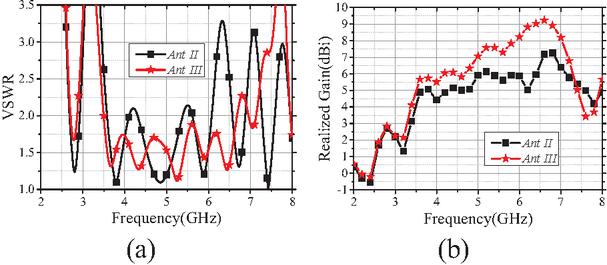
Figure 5 Comparison of simulated results between Ant II and Ant III (a) VSWR and (b) realized gain.
2.4 Ant IV
The surface currents on the VA brims satisfy the following equation:
| (8) |
where and represent the curvature and amplitude correction factor, and denotes the attenuation term proportional to the frequency. Symbols and are the length and height of the tapered slot, respectively. When the frequency decreases, unwanted currents on the VA leave more on the exponential tapered end, which will diffract along the outer brim of the VA and thus decrease the realized gain in the lower frequency. Ant IV, the proposed antenna, is based on Ant III, where rectangular slits are loaded slantwise on the outer brim of the VA to mitigate the excrescent currents and influence the radiation of the antenna. The configuration of the final antenna design and its detailed parameters are presented in Fig. 6.
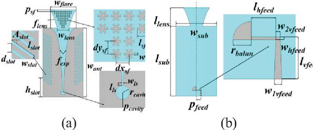
Figure 6 Configuration of the proposed antenna (a) front view (b) back view. , , .
With rectangular slits, simulated -field distributions of Ant IV at 3 GHz are presented in Fig. 7 (a), which are accumulated on rectangular slits and the top of the substrate. Introducing slits on the brims, surface currents on the brims are excited, and paths that currents pass are extended so that the effective size of the antenna design is enlarged and a bandwidth increase is realized in low frequencies. The worthiness of rectangular slits could be visualized by comparison of simulated VSWR and realized gain between Ant III and Ant IV presented in Figs. 7 (b) and (c), where impedance match and radiation of Ant IV are much improved in the low operating band. Simulated VSWR below 2 covers 2.57–6.72 GHz, and an expansion of 0.93 GHz of Ant IV is obtained in the low frequency band, which shows the ideal miniaturized effect of rectangular slits. Simulated realized gain reaches 6.61–8.84 dBi in this band. At 3 GHz, the simulated realized gain of Ant IV increases 6.4 dBi and 7 dBi compared to that of Ant III and Ant I, respectively. In the high band, however, the realized gain of Ant IV decreases a little due to the coupling between the snowlike MS and rectangular slits. Figure 7 (d) shows simulated PHC between Ant I and Ant IV. The minimum simulated PHC in the operating band of Ant IV is 8.3 MW, which is much bigger than simulated value of Ant I, demonstrating its value in applying to the HPM system.
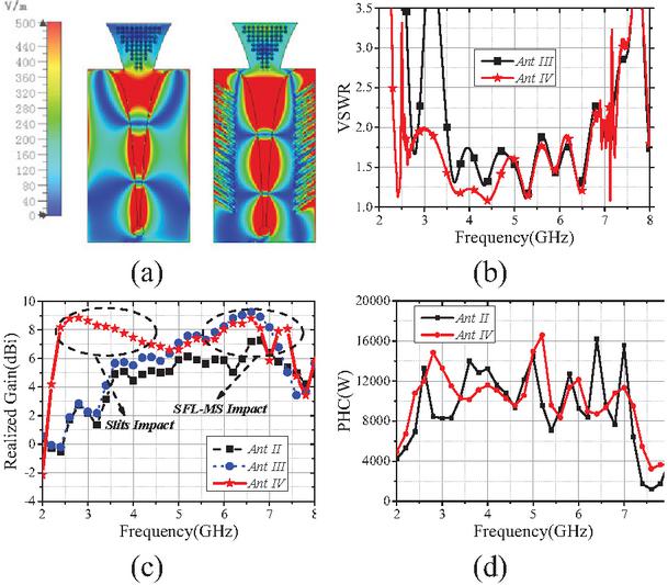
Figure 7 Comparison of simulated results between Ant III and Ant IV (a) E-field distribution at 3 GHz, (b) VSWR, (c) realized gain, and (d) PHC.

Figure 8 Comparison of -plane (left) and -plane (right) radiation patterns among Ant II, Ant III, and Ant IV (a) 3 GHz, (b) 4 GHz, (c) 5 GHz, and (d) 6 GHz.
Simulated radiation patterns of evolutionary VA at different frequency points are listed in Figs. 8 (a)–(d). Owing to the loading of rectangular slits and MS, it can be seen that the -plane obtains a more significant effect of beam narrowing than the -plane. In the low-frequency band, the realized gain of Ant IV is obviously bigger than that of Ant II and Ant III, and its main lobe radiates along the axis. For the asymmetry of antenna feeding, a slight deviation of the main lobe will occur at middle and high frequencies. With frequencies increasing, there is a significant growth in the magnitude of the back lobe. In the E-plane, the 3 dB beamwidth of Ant II, Ant III, and Ant IV covers , and at 3 GHz; the 3 dB beamwidth of Ant II, Ant III, and Ant IV covers , and at 4 GHz; the 3 dB beamwidth of Ant II, Ant III, and Ant IV covers , and at 5 GHz; the 3 dB beamwidth of Ant II, Ant III, and Ant IV covers , and at 6 GHz. Considering the -plane, the 3 dB beamwidth of Ant II, Ant III, and Ant IV covers , and at 3 GHz; the 3 dB beamwidth of Ant II, Ant III, and Ant IV covers , , and at 4 GHz; the 3 dB beamwidth of Ant II, Ant III, and Ant IV covers , and at 5 GHz; the 3 dB beamwidth of Ant II, Ant III, and Ant IV cover at 6 GHz. As for sidelobe characteristic, considering the symmetry and relative stability in the -plane, only sidelobes in the -plane are discussed. The sidelobe levels of Ant II, Ant III, and Ant IV reach 0.6 dB, 2.3 dB, and 19.3 dB at 3 GHz; sidelobe levels of Ant II, Ant III, and Ant IV reach 3.3 dB, 5.3 dB, and 9.3 dB at 4 GHz; sidelobe levels of Ant II, Ant III, and Ant IV reach 3.4 dB, 3.2 dB, and 5.9 dB at 5 GHz; sidelobe levels of Ant II, Ant III, and Ant IV reach 2.5 dB, 7 dB, and 7 dB at 6 GHz.
A comparison among Ant II, Ant III, and Ant IV with respect to bandwidth, realized gain, 3 dB beamwidth, sidelobe, and PHC are listed in Table 1. The observed frequency points are 3 GHz, 4 GHz, 5 GHz, and 6 GHz.
Table 1 Comparison among four evolution phases
| Ant | Bandwidth | Realized | PHC (kW) |
| Phase | (GHz) | Gain (dBi) | |
| Ant I | 3.26–8+ | 2.2/5.5/6.8/7.2 | 1.3/2.4/2.7/2.2 |
| Ant II | 4.31–5.39 | 2.2/4.4/5.9/5.8 | 8.3/13.2/14.4/9.3 |
| Ant III | 3.5–6.68 | 2.3/5.52/7.1/8.2 | 8.5/15.2/14.2/11.9 |
| Ant IV | 2.57–6.72 | 8.7/7.5/6.6/8.1 | 12.1/10.5/13.5/11 |
3 FABRICATION AND VERIFICATION
To validate simulated results of the proposed antenna, a prototype of the antenna model is fabricated as shown in Figs. 9 (a)–(c). An SMA-KE probe is employed for feeding, whose inner conductor and two pillars are connected with the microstrip balun on the back and the metal part on the front, respectively. The substrate and the feeding probe are clamped well due to the space between the inner conductor and two pillars. Compared to the all-metal HPM antenna, it takes advantage of the lightweight characteristic of the subloaded antenna. Weighed on the electronic scale, the proposed antenna is 19.4 g, which will greatly promote the movability of the HPM system. The antenna design is measured and verified in the anechoic chamber.

Figure 9 Fabrication of the proposed antenna: (a) prototype, (b) on the electronic scale, and (c) experimental verification in the anechoic chamber.
Simulated and measured VSWR results of the proposed antenna are exhibited in Fig. 10 (a). The measured VSWR below 2 and 2.5 covers 2.28–6.54 GHz and 2.21–7.17 GHz. In the band of 6.54–6.75 GHz, however, measured VSWR values are over 2. Simulated and measured realized gain results of the proposed antenna are shown in Fig. 10 (b), which are in accordance with each other. The measured realized gain can reach 6.56–8.15 dBi in the operating band. At middle frequencies, measured realized gain results are greater than simulated results. The black dotted line represents the simulated realized gain of Ant II and serves as a reference value for gain-enhancement calculation. Simulated and measured gain-enhancements are the blue dashed sequential line and blue discrete stars, which are attained by the deviation calculation between the proposed and the reference antenna, among which a 0.66–5.96 dBi realized gain-enhancement is obtained in the operating band, and the maximum value is at 3 GHz.

Figure 10 Simulated and measured results of the proposed antenna (a) VSWR and (b) realized gain.

Figure 11 Simulated and measured -plane and -plane radiation patterns of the proposed antenna: (a) 3 GHz, (b) 4 GHz, (c) 5 GHz, and (d) 6 GHz.
Table 2 Investigation of VA designs for gainenhancement techniques
| Ref. | Oper. Band (GHz) | Gain-Enh Method | Max Enh-Gain (dBi) | |
| [11] | 2.2 | 3.5–7/26.5–40 | Dual-Function Taper Slot | 2 |
| [12] | 2.5 | 2.4/5.2/5.8 | MS | 2.4 |
| [13] | 2.2 | 24.25–29.5 | MS | 3.16 |
| [14] | 2.2 | 5.4–18 | MS | 3.2 |
| [17] | 2.2 | 1–6 | MS Lens | 4.8 |
| [18] | 4.4 | 1.27–9.4 | MS | 2 |
| [19] | 2.2 | 0.45–10 | MS Layer | 6 |
| [21] | 3.55 | 1.5–55 | MS Lens | 5.5 |
| [22] | 3.48 | 22.5–45 | MS Lens | 6 |
| [23] | 3.55 | 10.2–41.75 | MS Lens | 4 |
| [24] | 10.2 | 3–9 | MS/SSPP | 3.75 |
| [25] | 3 | 1–28 | Director/MS | 4.5 |
| [26] | 3.55 | 15–27 | MS/SSPP | 2 |
| [27] | 2.2 | 0.45–10 | MS/CCSC | 3 |
| This Work | 10.2 | 2.28–6.54 | Slits/MS | 5.96 |
| The values of Max Enh-Gain (Maximum Enhanced-Gain) are approximate according to the data given by listed Refs. | ||||
Simulated and measured -plane and -plane radiation patterns of the proposed antenna at different frequency points match well, as shown in Figs. 11 (a)–(d). It is observed that, due to the loading of the SFL-MS, the -plane obtains an evident effect of beam narrowing than the -plane both on the simulation and measurement. In the E-plane, the measured 3 dB beamwidth of the proposed antenna cover , and at , and 6 GHz, respectively. In the -plane, the measured 3 dB beamwidth of the proposed antenna cover , , and at , and 6 GHz, respectively. The measured sidelobe levels in the -plane of proposed antenna reach 10.7 dB at at at 5 GHz, and 7.6 dB at 6 GHz. In the -plane, the simulated and measured sidelobe levels reach 10.5 dB at at at 5 GHz, and 6.7 dB at 6 GHz. Considering the dielectric loss and impedance mismatch brought by the substrate and weld craft, as well as machining and assembly tolerance, the deviation between the simulation and measurement is reasonable and the results are convincing enough to prove the performance of the proposed antenna.
As shown in Figs. 12 (a)–(c), an experiment was conducted to verify the ability in the HPM application of the proposed antenna. Specifically, a pulse-type HPM source, which outputs a pulse of 5000 W at 6 GHz, is included in the experience. Two proposed designs are of the proposed antenna. Specifically, a pulse-type HPM source, which outputs a pulse of 5000 W at 6 GHz, is included in the experiment. A proposed design and a horn antenna are involved as transmitting and receiving antennas, respectively. In the receiving terminal, a power meter is employed to monitor waveform variation. The average and peak power are 18.34 dBm and 19.92 dBm in 0 min. In 5 min they are 18.36 dBm and 19.87 dBm, respectively. There were no unexpected sounds, sparks, or smoke during the test. After the experiment, the outlook of the proposed antenna remained basically unchanged except for a high temperature on the surface, which may lead to metal falling off and further influence the lifetime of the proposed antenna.

Figure 12 Proposed antenna under high-power pulse-type: (a) diagram of the experiment, (b) 0 min, and (c) 5 min.
4 COMPARISON AND DISCUSSION
To better understand the proposed work in this paper, an investigation into relative public gain-enhanced VA design referring to operating band, sub, and gainenhanced method is listed in Table 2. Depending on the application, each antenna design has its positive and negative aspects. The proposed antenna obtains a satisfying maximum enhanced-gain 5.96 dBi benefit from the SFL-MS and slits with a relatively narrow operating band compared to the ultra-wideband characteristic of other VA designs for its PHC demand.
5 CONCLUSION
An HPM VA based on the substrate is proposed and verified in this paper. A substrate with high permittivity is employed to improve PHC so that the proposed antenna can sustain the energy released by the HPM source. An SFL-MS lens and rectangular slits are studied and added to the antenna design, which compensates for the radiation loss caused by the loading of the substrate and improves the directivity and impedance match. The prototype is fabricated and measured in a microwave anechoic chamber, whose results are acceptable and in reasonable agreement with simulated results, demonstrating its satisfying prospects in the solid-state HPM system.
ACKNOWLEDGMENT
This work is supported by National Key Laboratory of Science and Technology on Electromagnetic Environment Effects program (Grant No. JCKYS2025DC01) and the Science and Technology Innovation Program of Hunan Province under Grant 2023RC3265.
REFERENCES
[1] B. Wu, X.-Y. Sun, H.-R. Zu, and H.-H. Zhang, “Transparent ultrawideband halved coplanar Vivaldi antenna with metal mesh film,” IEEE Antennas Wireless Propag. Lett., vol. 21, no. 12, pp. 2532–2536, 2022.
[2] K. Zhang, R. Tan, Z. H. Jiang, Y. Huang, and L. Tang, “A compact, ultrawideband dual-polarized Vivaldi antenna with radar cross section reduction,” IEEE Antennas Wireless Propag. Lett., vol. 21, no. 7, pp. 1323–1327, 2022.
[3] C. Zhao, Y. Bai, and Q. Wei, “A 2 to 50 GHz all-metal Vivaldi antenna for ultra-wideband (UWB) application,” Int. J. Electron. Commun., vol. 148, no. 9, p. 154162, 2022.
[4] Z. Chen, R. Yin, Y. Jiang, and X. Mao, “An all-metal antipodal Vivaldi antenna design for high-power microwave application,” Applied Computational Electromagnetics Society (ACES) Journal, vol. 39, no. 12, 2024.
[5] T. H. Lim, S. Park, C. S. Lee, and J.-R. Park, “A broadband dual-slant polarized metal Vivaldi antenna for a high-power jammer,” in 2020 International Symposium in Antennas and Propagation (ISAP), Osaka, Japan, pp. 485–486, Jan. 2021.
[6] S. Ohm, E. Kang, T. H. Lim, and H. Choo, “Design of a dual-polarization all-metal Vivaldi array antenna using a metal 3D printing method for high-power jamming systems,” IEEE Access, vol. 11, pp. 35175–35181, 2023.
[7] Y. Chuo, L. Ziting, L. Qiang, and D. Haosheng, “Design of a metal Vivaldi antenna with wide band and dual polarization,” in 2021 IEEE International Workshop on Electromagnetics: Applications and Student Innovation Competition (iWEM), Guangzhou, China, pp. 1–3, Nov. 2021.
[8] X. Ma, S. Chai, K. Xiao, L. Ding, K. Xiao, and L. Ding, “Design of all-metal Vivaldi phased array antenna,” in 2018 IEEE 3rd International Conference on Signal and Image Processing (ICSIP), Shenzhen, China, pp. 547–551, Jul. 2018.
[9] M. Wang, L. Crocco, and M. Cavagnaro, “Antipodal Vivaldi antenna with ceramic cone lens for biomedical microwave imaging systems,” in 2021 15th European Conference on Antennas and Propagation (EuCAP), Dusseldorf, Germany, pp. 1–5, Mar. 2021.
[10] C. Rusch, J. Schäfer, T. Kleiny, S. Beer, and T. Zwick, “W-band Vivaldi antenna in LTCC for CW-radar nearfield distance measurements,” in Proceedings of the 5th European Conference on Antennas and Propagation (EUCAP), Rome, Italy, pp. 2124–2128, Apr. 2011.
[11] M. Wang, L. Crocco, S. Costanzo, and R. Scapaticci, “A compact slot-loaded antipodal Vivaldi antenna for a microwave imaging system to monitor liver microwave thermal ablation,” IEEE Open Journal of Antennas and Propagation, vol. 3, pp. 700–708, 2022.
[12] J. Ren, M. Zuo, B. Zhang, and X. Du, “Large frequency ratio Vivaldi antenna system with low-frequency gain enhancement utilizing dual-function taper slot,” IEEE Trans. Antennas Propag., vol. 70, no. 6, pp. 4854–4859, 2022.
[13] F. Gunes, I. O. Evranos, M. A. Belen, and P. Mahouti, “A compact triband antipodal Vivaldi antenna with frequency selective surface inspired director for IoT/WLAN applications,” Wireless Networks, vol. 27, pp. 3195–3205, 2021.
[14] A. S. Dixit and S. Kumar, “Gain enhancement of antipodal Vivaldi antenna for 5G applications using metamaterial,” Wireless Personal Communications, vol. 121, pp. 2667–2679, 2021.
[15] P. Das, S. Kundu, and R. Kumar, “A near zero refractive indexed non-uniform metasurface for broadband RCS reduction of an antipodal Vivaldi antenna,” Sci. Rep., vol. 8563, 2026.
[16] D. E. Bensafieddine, M. T. Taihi, H. Merah, S. M. Chaker, F. Babaghayou, F. Djerfaf, L. Merah, M. Bouzouad, and T. Seghier, “A metafractal cell-based reconfigurable Vivaldi antenna for non-invasive detection of malignant skin tissues,” AEU-International Journal of Electronics and Communications, vol. 210, p. 156298, 2026.
[17] S. Pan, W. Shen, Y. Feng, and Z. Liu, “Miniaturization and performance enhancement of Vivaldi antenna based on ultra-wideband metasurface lens,” Int. J. Electron. Commun., vol. 134, no. 6, p. 153703, 2021.
[18] K. Li, Z. Li, X. Liu, S. Li, X. Qu, Z. Yang, and W.-H. Zong, “A high-gain Vivaldi antenna loaded with metasurface for broadband applications,” Applied Computational Electromagnetics Society (ACES) Journal, vol. 39, no. 10, pp. 876–884, 2024.
[19] A. Hossain, S. Pancrazio, T. Kelley, and A.-V. Pham, “A compact and low-profile high-gain multilayer Vivaldi antenna based on gradient metasurface superstrates,” IEEE Antennas Wireless Propagation Letters, vol. 24, no. 6, pp. 1537–1541, 2025.
[20] P. Zhou, M. Li, Q. Chen, P.-F. Gu, and D.-Z. Ding, “Metasurface-loaded ultrawideband differential Vivaldi antenna with reflectionless notched band,” IEEE Antennas and Wireless Propagation Letters, vol. 25, no. 2, pp. 516–520, 2026.
[21] O. Yesilyurt and G. Turhan-Sayan, “Metasurface lens for ultra-wideband planar antenna,” IEEE Trans. Antennas Propag., vol. 68, no. 2, p. 726, 2020.
[22] P. K. Jaiswal, R. Bhattachary, and A. Kumar, “A UWB antipodal Vivaldi antenna with high gain using metasurface and notches,” Int. J. Electron. Commun., vol. 159, no. 4, p. 154473, 2023.
[23] A. Azari, A. Skrivervik, H. Aliakbarian, and R. A. Sadeghzadeh, “A super wideband dual-polarized Vivaldi antenna for 5G mmWave applications,” IEEE Access, vol. 11, pp. 80761–80768, 2023.
[24] J. Liang, C. Chiu, T. Lin, and C. Lee, “An ultrawideband circularly-polarized Vivaldi antenna with high gain,” IEEE Access, vol. 10, pp. 100446–100455, 2022.
[25] H. Qi and H. Liu, “Wideband high gain differential Vivaldi antenna design based on exponential spoof surface plasmon polaritons metamaterial,” Int. J. Electron. Commun., vol. 163, p. 154603, 2023.
[26] X. Shi, Y. Cao, Y. Hu, and X. Luo, “A high-gain antipodal Vivaldi antenna with director and metamaterial at 1–28 GHz,” IEEE Antennas Wireless Propag. Lett., vol. 20, no. 12, pp. 2432–2436, 2021.
[27] H. Qi and H. Liu, “Wideband high-gain filtering Vivaldi antenna design based on MS and herringbone SSPP structure,” IEEE Antennas Wireless Propag. Lett., vol. 22, no. 8, pp. 1798–1802, 2023.
[28] A. Hossain and A.-V. Pham, “A novel gain-enhanced miniaturized and lightweight Vivaldi antenna,” IEEE Trans. Antennas Propag., vol. 71, no. 12, pp. 9431–9439, 2023.
BIOGRAPHIES

Zichong Chen received the M.E. degree from Hunan University, China, in 2023. He is an engineer for Hunan Vanguard Group Co. Ltd. His research interests include HPM antenna design and solidstate high-power microwave systems with active phased array architecture.

Fangsheng Cai received the M.E. degree from Nanjing University of Aeronautics and Astronautics, China, in 2021. He works full-time as a microwave engineer at Hunan Vanguard Group Co. Ltd. His current research interests include HPM systems based on electric vacuum sources.

Peng Bai received the M.E. degree from Yunnan University, China, in communication engineering in 2023. He works full-time as a microwave engineer at Hunan Vanguard Group Co. Ltd. His current research interests include HPM antenna systems.

Taijing Shi received the M.S. degree from Beijing University of Chemical Technology, China, in 2019. She works full-time as a senior microwave engineer at Hunan Vanguard Group Co. Ltd. Her current research interests include the HPM effect and assessment.

Xiaojun Mao received the Ph.D. degree from Harbin Engineering University, China, in 2017. He works full-time as a senior microwave engineer at Hunan Vanguard Group Co. Ltd. His current research interests include the HPM overall system design and radar technology.

Yun Jiang received the Ph.D. degree from National University of Defense Technology, China, in 2022. He works full-time as a senior microwave engineer at Hunan Vanguard Group Co. Ltd. His current research interests include HPM overall system design, microwave RF circuits, and radar technology.
ACES JOURNAL, Vol. 41, No. 4, 343–352
DOI: 10.13052/2026.ACES.J.410406
© 2025 River Publishers