A Single-Layer Reflectarray Unit Cell with Enhanced Performance Using Dual Concentric Split-Circle Rings
Likaa S. Yahya1 and Khalil H. Sayidmarie2
1Polytechnic College Mosul
Northern Technical University, Mosul, Iraq
likaasalim@ntu.edu.iq
2College of Electronics Engineering
Ninevah University, Mosul, Iraq
kh.sayidmarie@uoninevah.edu.iq
Submitted On: July 22, 2025; Accepted On: March 08, 2026
Abstract
This paper proposes a dual-ring unit cell design for a single-layer reflectarray antenna. The element is attained using two concentric split-ring resonators, where each ring is divided into four equal sections. By adjusting the width, scaling, and radius of the concentric split-rings, two distinct resonance frequencies are realized in each ring, attributable to the electric length inside the rings. This approach yields a wider phase range for the reflection coefficient, with a nearly linear phase response. Three different configurations are investigated to identify the best performance parameters. The electromagnetic behavior of the proposed unit element is simulated using CST Microwave Studio Suite. The reflection characteristics are analyzed using the infinite-array model with Floquet port excitation. Hexahedral meshing is employed for the antenna configuration, with the mesh density adjusted according to the wavelength to validate sufficient resolution of the structural features. The unit cell was also investigated using the HFSS frequency-domain solver based on the finite integration technique. An equivalent circuit was found using the Advanced Design System (ADS). The simulation results indicate that all three configurations offer a broad phase variation, with the minimum phase of approximately 885∘ at 10 GHz in case 2, and a maximum phase slope of 68∘/mm at 12 GHz in case 1, over the 8–12 GHz frequency range. The configuration in case 3 achieves the widest operational bandwidth of 26.8% centered at 10 GHz.
Keywords: Bandwidth improvement, single-layer, split-circle rings, unit cell, wideband reflectarray..
1 INTRODUCTION
Reflectarray antennas symbolize a promising class of high-gain antennas with several advantages, including lightweight construction, low profile, low cost, and reduced fabrication complexity. Furthermore, they enable higher antenna gains by developing the reflective behavior of their elements [1]. In its essential configuration, a reflectarray antenna comprises a feed element and an aperture composed of an array of microstrip patches. The primary purpose of the reflectarray is to reflect the incident waves from the feed and to shape and direct the resulting collimated beam in a specific direction. Each element in the array is designed to provide the required phase shift upon reflection, ensuring proper wave collimation and steering the beam toward the intended target direction [2, 3]. Nevertheless, the performance of reflectarrays may degrade due to improper reflection phase settings and their inherently narrow-band behavior. Numerous studies have proposed different techniques to extend the phase range of the reflection coefficient and enhance bandwidth. Some approaches involve multilayer configurations; for instance, multilayers of double concentric annular rings for X-band applications were proposed in [4]. The design described in [5] involves stacked microstrip patches and demonstrates good performance in dual-frequency operation. Additionally, a reflectarray consisting of three stacked layers with rectangular patches was presented in [6], offering dual-polarization functionality that is suitable for space applications. A 4-layer transmitarray antenna composed of double square-ring elements was discussed in [7]. Other techniques focus on element rotation; for example, adjusting the rotation angle of the elements as explored in [8, 9, 10, 11]. A third method involves attaching phase delay lines to the radiating elements for phase compensation. By varying the lengths of arc stubs or phase delay lines, broadband performance can be attained, as demonstrated in [12, 13, 14, 15]. The fourth technique, which is the most commonly used and the simplest to manufacture, involves varying the size of an element within a multi-resonant geometry to produce phase variation, as detailed in [16, 17, 18, 19, 20].
An essential feature in the design of a reflectarray microstrip antenna is the selection of a suitable element shape, commonly referred to as the unit cell, along with its size, followed by the total number of cells, and the overall array configuration. Each element independently contributes to phase amendment, thus enabling the achievement of the desired directivity [21]. The choice of the radiating element’s shape is particularly critical, as the scattering of the incident electromagnetic field is strongly influenced by its geometry. Thus, an important objective is to identify a cell category that provides a broad reflection coefficient phase range when its properties are varied [21]. It is well-established that a phase variation restricted to less than 360∘ can result in a reduction of the antenna’s directivity [16]. Conversely, research indicates that the phase variation with respect to any geometrical parameter should be as linear as possible, confirming a smooth slope in the phase response [22]. This requires that the full 360∘ phase shift is attained through very gradual variations of the parameter. In practical applications, abrupt phase changes tend to lead to narrower working bandwidths and complicate the manufacturing process of the radiating elements due to tight tolerances [23]. Usually, the phase of the reflection coefficient as a function of the patch dimensions is calculated to assess whether the phase range is adequately wide and whether the curve reveals a smooth slope. Accordingly, extensive effort is often invested in identifying a unit cell capable of providing the desired phase characteristics. Commonly employed microstrip patch shapes include squares, crosses, rectangles, circles, and rings [24, 25, 26, 27, 28, 29].
In this study, double split-circle rings are used to enhance both the phase range and the bandwidth of a unit cell for a reflectarray antenna. The dual split-ring resonator elements create multiple resonance frequencies. By separating each ring into four segments and systematically varying the scale, width, and size of these segments, two adjacent resonances are generated by each ring. This modification improves the phase coverage and bandwidth of the unit element reflectarray.
The paper is arranged as follows. Section 2 details the design methodology of the proposed dual-band unit cell. Section 3 presents the obtained simulation results for both the single split-circle ring and the dual split-circle ring reflectarray unit cells. Section 4 describes the equivalent circuit of the proposed double split-circle rings reflectarray unit cell. A comparative investigation of the proposed unit cell with existing published work is presented in section 5. Lastly, the conclusions are explained in section 6.
2 DUAL-BAND SPLIT-CIRCLE RINGS CONFIGURATION
The reflectarray antenna suggested in [30] is adopted as a baseline for the current research. In this design, the original circular shape, divided into four quadrants, is now modified into a split circular ring and then transformed into a double split circular ring. The element is designed on a 0.16 mm thick Taconic TLC-32 substrate, characterized by a relative permittivity of and a loss tangent tan . This substrate is supported by a 3 mm thick foam layer with , backed by a conducting ground plane with a thickness of 0.035 mm. The chosen unit cell dimensions are 1818 mm, corresponding to approximately (0.60.6), where is the free-space wavelength at the operating frequency of 10 GHz. For the design of the dual split circular ring structure, the permittivities of the two substrates are denoted as and , with heights H1 and H2, respectively. Initially, the total thickness (HT) and the effective permittivity () can be determined using equations (1) and (2) [31]
| (1) | |
| (2) |
The unit cell dimensions in a split-circle ring reflectarray are classically governed by the resonant performance of the ring elements. A ring patch acts as a resonant loop. Common practice is to relate the ring circumference to the effective wavelength . The frequency features of the dual split-ring antenna were calculated as follows.
A ring of average radius R has a perimeter 2R. The ring resonates when
| (3) |
where is the harmonic number, which is unity in this case, and is the effective wavelength that can be calculated as [2]
| (4) |
where is the speed of light in meters/second, and is the resonant frequency of each ring [11]:
| (5) |
where is the effective permittivity relative to the ground plane and can be calculated as [2]
| (6) |
Since the unit cell is designed to operate in the 8–12 GHz frequency band, the outer ring is designed to operate at 8 GHz, while the inner ring is designed to operate at 12 GHz. Substituting into equations (1–6), , . Thus, the mean radius of the outer ring is equal to 5.6 mm, while the mean radius of the inner ring is equal to 3.75 mm.
The design methodology for the dual-band split circular ring-based reflectarray is illustrated in Fig. 1. The configuration of the unit cell used for the proposed phase shifting element is depicted in Fig. 2. This element consists of two concentric split circular rings, with the diameters of the inner and outer rings being varied to achieve the desired phase variation over the specified operational band. The two rings are separated by a small, constant gap to facilitate the excitation of two adjacent resonant frequencies. All the designs presented in this work were analyzed using CST Studio Suite, modeling the unit cells within an infinite array structure. The excitation was modeled using Floquet port boundary conditions. This approach thoroughly accounts for the true shape of the radiating elements and the effects of the mutual coupling and is widely regarded as a sound simulation methodology for reflectarray antenna design.
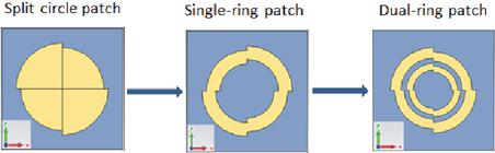
Figure 1 Design methodology of a dual-band split-circle ring reflectarray element.
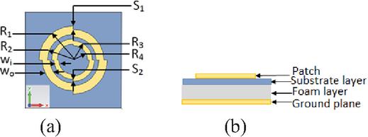
Figure 2 Configuration of the unit cell for the proposed phasing element (a) front view and (b) side view.
3 SIMULATION RESULTS
3.1 Single split-circle ring reflectarray unit cell
The investigation starts with a basic unit cell comprising a single disk of a split-circle element operating at a central frequency of 10 GHz within the X-band [30]. The outer sector radius, R1 (d/2), is set to 6.1 mm, while the inner sector radius is defined as R1 – 0.1R1, corresponding to a scale factor S 0.9. The amplitude and phase responses as functions of frequency are presented in Fig. 3 (a). The phase of the reflected field is zero at the nominal operating frequency of 10 GHz and shows a phase variation of approximately 601∘ across the frequency range of 8 to 12 GHz. At the resonance point, the scattered field magnitude drops to a minimum of 0.4 dB, corresponding to very low attenuation. Figure 3 (b) explains the variation of the amplitude and phase of the reflected field at 10 GHz for different values of the outer diameter. It can be noted that the reflected phase can be effectively controlled within a range from 94.7∘ to 660.7∘, corresponding to a phase range of 566∘, by varying the outer diameter from 4 mm to 13 mm. Within this range, the amplitude variation is approximately 0.43 dB.
For enhanced phase response performance, a split-circle ring is derived from the original disk split-circle. This split-circle ring is designed specifically for X-band microstrip reflectarrays. The element introduces three degrees of freedom to tailor the phase response: the first is the overall size, the second is the width of the ring, and the third is the scaling factor for the inner ring radius, which represents the differences in the distances between adjacent sectors. These parameters are carefully considered to select the element shape that demonstrates optimal performance in terms of lower phase slope relative to size and frequency, quantified by the derivatives (L), and (f), respectively. Figure 4 (a) illustrates the amplitude and phase variation versus frequency for a split-circle ring with a scale factor of 0.9. The results reveal that the resonance frequency shifts toward the lower band, from 10 GHz to approximately 8.87 GHz, compared to the original disk element. Figure 4 (b) displays the amplitude and phase of the reflected field at 10 GHz for this split-circle ring. It is evident that the reflected phase can be controlled over a range from 102.3∘ to 729∘, corresponding to a phase variation of 626.7∘, when the outer diameter is varied from 4 mm to 13 mm. This represents a phase range improvement of approximately 60.7∘ compared to the original disk split-circle. Within this range, the amplitude variation remains minimal, about 0.04 dB.
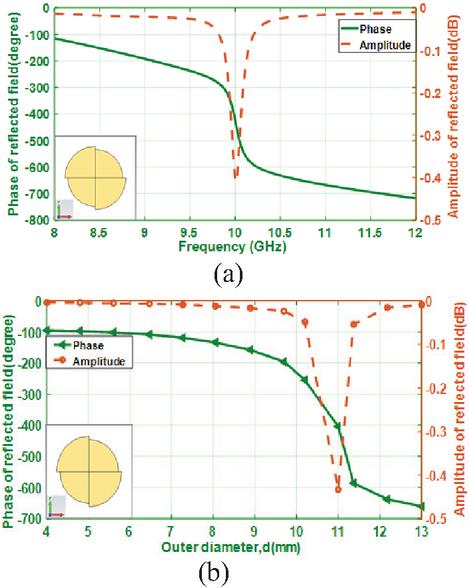
Figure 3 Amplitude and phase characteristics of the reflected field from the split-circle reflectarray unit cell (a) variation with frequency and (b) variation with outer diameter at 10 GHz.
Figure 5 (a) examines the phase and amplitude variation of the reflected field for the split-circle ring with four different scale factors (S 1, 0.9, 0.8, 0.7). The widths of both sectors are fixed at 1.8 mm, and the ratio between the widths of consecutive sectors remains constant at 1. It is observed that when S=1, corresponding to a traditional ring, the phase range is approximately 274.3∘ (from 60.1∘ to 334.4∘), which is less than the required 360∘ phase range for the reflectarray. Conversely, reducing the scale from 1 to 0.7 significantly increases the phase range to approximately 627∘ from (102∘ to 729∘), with a slight decrease in the phase slope as the scale is reduced. Figure 5 (b) depicts the variation of the reflected phase and amplitude for split-circle rings with various sector width ratios (w1/w2 0.7, 0.6, 0.5, 0.4), maintaining a constant scale factor (S 0.8). The results indicate that decreasing the width ratio slightly reduces the phase range. The maximum phase range of approximately 649∘ occurs at w1/w2 0.7, while the minimum of about 617∘ is observed at w1/w2 0.4. Additionally, the phase slope becomes more linear as the width ratio decreases.
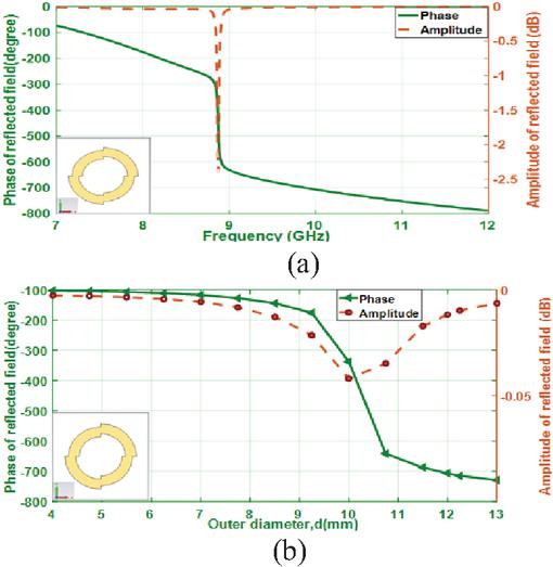
Figure 4 Amplitude and phase of the scattered field by the split-circle ring unit cell: (a) frequency variations and (b) outer diameter variations at 10 GHz.
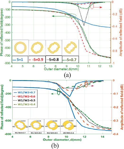
Figure 5 Amplitude and phase of the scattered field from the split-circle ring unit cell: (a) outer diameter variations for four different scales (S 1, 0.9, 0.8, 0.7) and (b) outer diameter variations for four different widths (w1/w2 0.7, 0.6, 0.5, 0.4) at 10 GHz.
3.2 Dual split-circle rings reflected array unit cell
To enhance the phase characteristics of a unit cell, uniplanar phasing elements in the form of double split-circle rings are considered, as illustrated in Figs. 6, 7, and 8. This study investigates three distinct structures. Figure 6 presents the amplitude and phase responses of a unit cell containing two concentric split-circle rings, conforming to the first case. In this configuration, the scale factor of the outer ring (S1) is equal to 0.92, which relates to the gap between two adjacent outer sectors, while the scale factor of the inner ring (S2) is equal to 0.84. The ratio of the width of the inner ring (wi) to that of the outer ring (wo) is equal to 0.7 (wi/wo 0.7). Additionally, the size ratio of the inner to outer rings is approximately 0.67. In the inner ring, each sector makes contact only with its adjacent sector. Three resonant frequencies are observed in Fig. 6 (a): the first, at 8 GHz, is primarily attributed to the outer ring, and the second and third, at 11 GHz and 12 GHz, are attributed to the inner ring. Differences in the splitting of the sectors create two distinct current paths within the inner ring, resulting in dual resonances. Figure 6 (b) illustrates the phase variation of the reflected wave from the unit cell as a function of the outer diameter (d 2*R1) at four frequencies (10, 11, 12, and 13 GHz), with the calculated values listed in Table 1. It is apparent that increasing the frequency from 10 GHz to 13 GHz broadens the phase range from approximately 979.5∘ to 1338.3∘, with the phase slope increasing from 42.65∘/mm at 10 GHz to 82.95∘/mm at 13 GHz. The phase range enhancement of approximately 35% is significant compared to a single split-circle ring at 10 GHz.
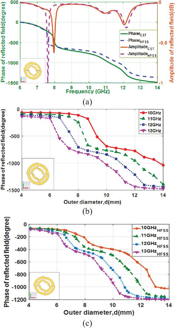
Figure 6 Amplitude and phase of the scattered field by the double split-circle rings unit cell (case 1): (a) frequency variations in CST and HFSS; (b) variation with outer diameter at frequencies 10, 11, 12, and 13 GHz in CST; and (c) variations with outer diameter at frequencies 10, 11, 12, and 13 GHz in HFSS.
To validate the simulation results, another simulation was performed for the design shown in the first case using the HFSS software package, and the obtained results are shown in Figs. 6 (a) and (c) and Table 2. The figure shows a good match between the results of the two software packages, although the results obtained using the CST simulation seem better in terms of the frequency range being higher and the slope being lower. It is known that the HFSS package uses the finite element method, while the CST uses the finite integration technique, which means that two different approaches are used. Therefore, one approach can be considered as a confirmation of the other one. The good agreement between the results obtained from both can be considered a validation.
Table 1 Characteristics and phase response of the double split-circle rings reflectarray unit cell in CST (case 1)
| Case 1 CST | ||||
| Parameter | 10 GHz | 11 GHz | 12 GHz | 13 GHz |
| Slope (∘/mm) | 42.65 | 55.73 | 67.5 | 82.95 |
| Slope (∘/GHz) | 48 | 107 | 90 | 119 |
| Max. phase (∘) | 59.5 | 84.8 | 110.6 | 136.7 |
| Min. phase (∘) | 1039 | 1394 | 1442 | 1475 |
| Phase range (∘) | 979.5 | 1309 | 1331.4 | 1338.3 |
Table 2 Characteristics and phase response of double split-circle rings reflectarray unit cell in HFSS (case 1)
| Case 1 HFSS | ||||
| Parameter | 10 GHz | 11 GHz | 12 GHz | 13 GHz |
| Slope (∘/mm) | 50.3 | 60.12 | 79 | 92.22 |
| Slope (∘/GHz) | 82.33 | 175 | 207 | 78 |
| Max. phase (∘) | 63.4 | 62 | 73 | 73.5 |
| Min. phase (∘) | 1031 | 1158 | 1183 | 1202 |
| Phase range (∘) | 967.6 | 1096 | 1110 | 1128.5 |
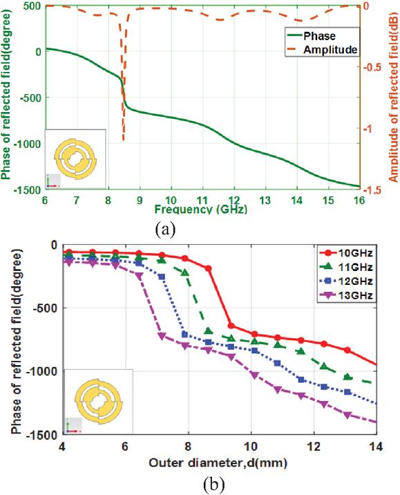
Figure 7 Amplitude and phase of the field scattered by the double split-circle rings reflectarray unit cell (case 2): (a) frequency variations and (b) outer diameter variations at frequencies 10, 11, 12, and 13 GHz.
In the second structure, the widths of the two inner ring sectors differ, with the narrow sector’s width being 0.4 times that of the wider sector (w1/w2 0.4), and the ratios of their widths to the outer ring being w1/wo 0.72 and w2/wo 1.83, respectively. Figure 7 shows the amplitude and phase characteristics as a function of frequency and the outer diameter (d 2*R1), with the corresponding data listed in Table 3.
Figure 7 (a) demonstrates four resonance frequencies. The first resonance happens at 7.57 GHz, followed by the next resonance at 8.47 GHz. These double frequencies are attributed to the outer ring shape. The third and fourth resonances are detected at 11.57 GHz and 14.1 GHz, respectively, and are related to the inner ring. Figure 7 (b) illustrates the variation of the outer diameter in relation to the phase of the reflected field at frequencies of 10 GHz, 11 GHz, 12 GHz, and 13 GHz. The phase slope (d) values at the four frequencies decrease as compared to the first case, indicating increased linearity, and the overall phase range declines compared to the first case. In the third case, the inner ring size is set to 62.5% of the outer ring size, with the outer ring width at 0.25R1 and the inner ring width at 0.15R1. Figure 8 (a) reveals two resonance frequencies at approximately 8.15 GHz and 11.8 GHz. Figure 8 (b) presents the phase responses at four frequencies (10, 11, 12, and 13 GHz), with the corresponding values listed in Table 4. The minimum phase range is approximately 897∘ at 10 GHz. As the frequency increases from 10 GHz to 13 GHz, the phase range increases to a maximum of approximately 1276∘ at 13 GHz.
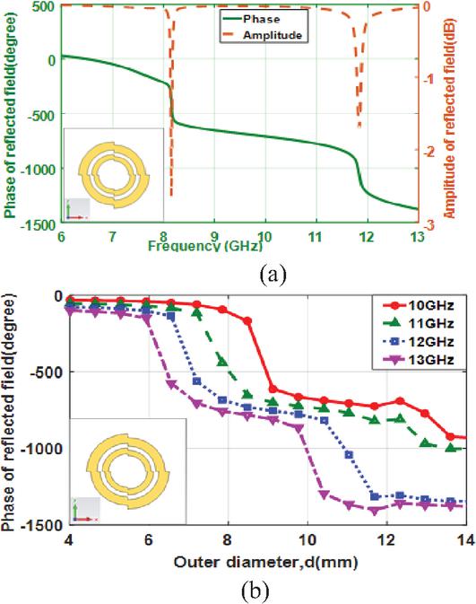
Figure 8 Amplitude and phase of the field scattered by the double split-circle rings reflectarray unit cell (case 3): (a) frequency variations and (b) outer diameter variations at frequencies 10, 11, 12, and 13 GHz.
Table 3 Characteristics and phase response of double split-circle rings reflectarray unit cell (case 2)
| Case 2 | ||||
| Parameter | 10 GHz | 11 GHz | 12 GHz | 13 GHz |
| Slope (o/mm) | 41 | 52 | 62 | 72 |
| Slope (o/GHz) | 66 | 73 | 86 | 93.7 |
| Max. phase (∘) | 60 | 85.3 | 111 | 137.4 |
| Min. phase (∘) | 945 | 1094 | 1254 | 1398 |
| Phase range (∘) | 885 | 1008.7 | 1143 | 1261 |
Table 4 Characteristics and phase response of double split-circle rings reflectarray unit cell (case 3)
| Case 3 | ||||
| Parameter | 10 GHz | 11 GHz | 12 GHz | 13 GHz |
| Slope (o/mm) | 44.5 | 52 | 68 | 78 |
| Slope (∘/GHz) | 63 | 68.5 | 69.5 | 80.3 |
| Max. phase (∘) | 31 | 54.5 | 77.6 | 101.8 |
| Min. phase (∘) | 928 | 1004 | 1345 | 1378 |
| Phase range (∘) | 897 | 949.5 | 1267.4 | 1276.2 |
3.3 Bandwidth of dual split-circle rings reflected array unit cell
It has been demonstrated in [32] that the major factor influencing the bandwidth of a microstrip reflectarray is the bandwidth of the singular radiating elements. The bandwidth can be expressed as the frequency range over which the phase variation reaches a specified value; . was considered to be in [32]. The bandwidth is defined as (B.W. f2–f1), where f1 and f2 are the frequencies corresponding to phase variation of 90∘, and can be determined from the curves presented in Figs. (3 (a), 6 (a), 7 (a), and 8 (a)). Table 5 summarizes the reflection phase bandwidths of the split-circle and double split-circle ring reflectarray unit cells for the three cases discussed above. It can be seen that adding a second ring results in a wider band, and the third case achieved the highest bandwidth of 26.8%.
Table 5 The achieved bandwidth for the unit cells of the three proposed designs compared to that for the split-circle at 10 GHz
| at fr [∘] | f1 at GHz | f2 at GHz | B.W. f2–f1 | B.W % | |
| Split-circle element at s 0.9 | 423 | 9.93 | 10.06 | 0.13 | 1.3 |
| Case 1 | 773 | 8.78 | 10.64 | 1.86 | 18.6 |
| Case 2 | 755 | 8.66 | 10.9 | 2.24 | 22.4 |
| Case 3 | 710 | 8.54 | 11.22 | 2.68 | 26.8 |
4 EQUIVALENT CIRCUIT OF THE UNIT CELL
To better understand the proposed design, the structure is represented as an equivalent circuit. The equivalent circuit diagram of the proposed double split-circle rings reflectarray unit cell (the second design) is simulated using the Advanced Design System (ADS) software and is presented in Fig. 9. As each ring is split, the external split-ring is modeled via a pair of series RLC circuits, and the internal split-ring is similarly modeled by a pair of series RLC circuit, the two parallel branches combination are connected through capacitance C1, which characterizes the mutual coupling between the dual-rings. The resonant modes are mode-1 at fr1 7.62 GHz, mode-2 at fr2 8.2 GHz, mode-3 at fr3 10.9 GHz, and mode-4 at fr4 11.8 GHz, which are characterized by the electrical triplets parameters (R1, L1, C1), (R2, L2, C2), (R3, L3, C3), and (R4, L4, C4), respectively. The antenna transmission line is represented by inductance L1 and capacitance C2, where L1 accounts for higher-order modes, and C2 corresponds to the quasi-static input capacitance, while Term1 symbolizes the Floquet port. The electrical parameters are tuned to support the resonance frequencies of modes 1, 2, 3, and 4. Figure 10 compares S11 magnitude and phase plots between the ADS equivalent circuit and CST simulation results. The figure shows that the results from the equivalent circuit model are in good agreement with those from CST. A small discrepancy in magnitude (0.03 dB) is seen at the second frequency band, which can be attributed to higher-order modes of the structure. It is noted that the proposed equivalent-circuit model, as defined, is an approximate representation circuit. Although it does not perfectly match the CST simulations, it remains a useful tool for explaining the structure’s operating principle and confirming the results.
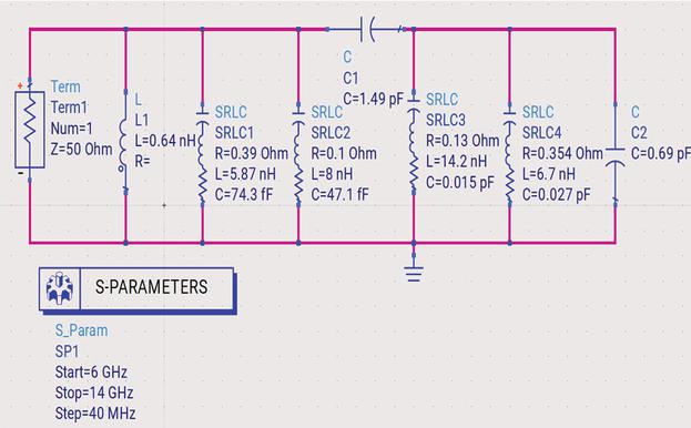
Figure 9 Equivalent circuit model of the proposed unit cell reflectarray.
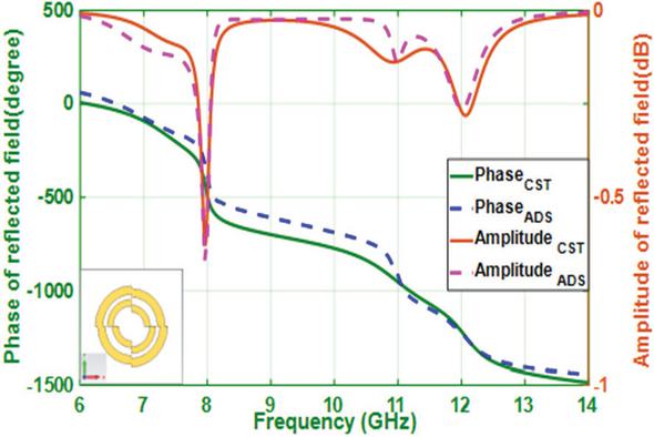
Figure 10 Reflection coefficient values (in amplitude and phase) obtained from the equivalent circuit compared to those found from the CST simulations.
5 COMPARISON WITH OTHER PUBLISHED WORK
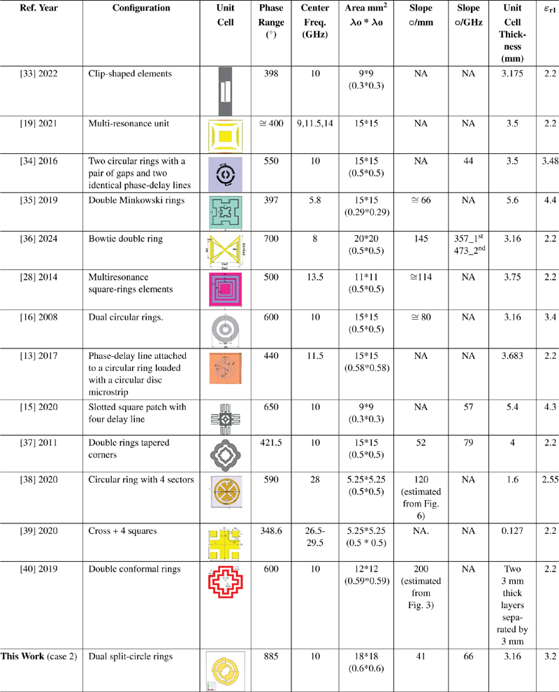
The performance of the proposed reflectarray antenna is compared with that of other designs reported in the literature, as summarized in Table 6. This specifies that the established design attains the broadest phase range, nearly 885∘, and the lowest phase slope 41∘ per mm, over the X-band frequency range (8–12 GHz) among all configurations studied. The smooth phase of the proposed unit cell results in the lowest phase sensitivity of 66∘ per GHz compared with the values reported in [36, 37]. It is perceived that the proposed antenna combines the improvements of both phase-range enhancement approaches and displays superior performance in terms of slope, dispersion, and design simplicity relative to most designs.
The advantages of the proposed design stem from the dual-ring feature, which inherently exhibits dual-resonance behavior. Moreover, splitting the ring further enhances multi-resonance performance. Although the dual circular ring features have been used in other designs [13, 16, 28, 37], but the split-ring has enhanced the phase response compared to other designs.
Table 6 Comparing the proposed design with other published works
6 CONCLUSION
The paper demonstrated a low-profile, single-layer microstrip reflectarray element incorporating dual split circular rings as the fundamental unit cell. The design aimed to enhance phase range coverage and bandwidth performance by altering the geometric parameters of the split-rings. The inclusion of dual concentric split-circle rings creates multiple resonant modes, thereby extending the bandwidth and supporting a near-linear phase response over a wide frequency range. The proposed design comprises double split-ring shapes printed onto a thin (0.16 mm) Taconic TLC-32 substrate, supported by a 3 mm thick layer of low-permittivity foam (relative permittivity of 1.05). By adjusting the geometric parameters of the rings, the phase characteristic can be approximated as a linear function of the ring dimensions. The study tests three distinct cases, which offered a minimum phase range of 885∘ and a phase slope of 41∘/mm at 10 GHz, along with a relative bandwidth of 18.65%. The results demonstrated significant improvements in phase coverage and bandwidth performance compared to previous reflectarray designs.
The equivalent circuit results showed that the dual split-ring unit cell has four resonance frequencies corresponding to the two split-rings.
The split circular ring unit cell utilizes multi-resonance configurations to avoid the complex and costly fabrication of multi-layer reflectarrays while still achieving wide bandwidth, thereby making it suitable for a range of applications, including satellite communications, radar systems, and remote sensing.
References
[1] J. Huang and J. A. Encinar, Reflectarray Antennas. New Jersey: Wiley, 2007.
[2] R. D. Javor, X.-D. Wu, and K. Chang, “Design and performance of a microstrip reflectarray antenna,” IEEE Transactions on Antennas and Propagation, vol. 43, no. 9, pp. 932–939, Sep. 1995.
[3] P. Nayeri, F. Yang, and A. Z. Elsherbeni, Reflectarray Antennas: Theory, Designs, and Applications. New Jersey: John Wiley & Sons Ltd, 2018.
[4] N. Misran, R. Cahill, and V. Fusco, “Design optimisation of ring elements for broadband reflectarray antenna,” IEE Proc.-Microw. Antennas Propag., vol. 150, no. 6, pp. 440–444, 2003.
[5] J. A. Encinar, “Design of a dual frequency reflectarray using microstrip stacked patches of variable size,” Electronics Letters, vol. 32, no. 12, pp. 1049–1050, 1996.
[6] G. Zhao and Y.-C. Jiao, “Broadband dual-polarization dual coverage reflectarray antenna,” in Proceedings of the IEEE 4th International Symposium on Microwave, Antenna, Propagation, and EMC Technologies for Wireless Communications (MAPE ’11), pp. 102–105, Nov. 2011.
[7] X. Chua, T. Chia, and K. B. K. Chia, “Design of a transmitarray antenna using 4 layers of double square ring elements,” Progress in Electromagnetics Research Letters, vol. 94, pp. 141–149, 2020.
[8] J. Huang and R. J. Pogorzelski, “A Ka-band microstrip reflectarray with elements having variable rotation angles,” IEEE Transactions on Antennas and Propagation, vol. 46, no. 5, pp. 650–656, May 1998.
[9] R. Florencio, J. A. Encinar, R. R. Boix, G. Pérez-Palomino, and G. Toso, “Cross-polar reduction in reflectarray antennas by means of element rotation,” in IEEE 10th European Conference on Antennas and Propagation (EuCAP), pp. 1–5, 2016.
[10] X. Yang, S. Xu, F. Yang, M. Li, Y. Hou, S. Jiang, and L. Liu, “A broadband high-efficiency reconfigurable reflectarray antenna using mechanically rotational elements,” IEEE Transactions on Antennas and Propagation, vol. 65, no. 8, pp. 3959–3966, 2017.
[11] B. Strassner, C. Han, and K. Chang, “Circularly polarized reflectarray with microstrip ring elements having variable rotation angles,” IEEE Transactions on Antennas and Propagation, vol. 52, no. 4, pp. 1122–1125, Apr. 2004.
[12] I. Derafshi, N. Komjani, E. G. Mizuji, and M. Mohammadirad, “A novel FSS backed unit cell with quasi spiral phase delay line,” Journal of Microwaves, Optoelectronics and Electromagnetic Applications, vol. 15, no. 3, pp. 225–236, Sep. 2016.
[13] W. S. Elshennawy and A. M. Attiya, “Modified phasing element for broadband reflectarray antennas,” Progress in Electromagnetics Research C, vol. 71, pp. 9–16, 2017.
[14] R. S. Malfajani and Z. Atlasbaf, “Design and implementation of a broadband single-layer circularly polarized reflectarray antenna,” IEEE Transactions on Antennas and Propagation, vol. 11, pp. 973–976, 2012.
[15] T. Shabbir, M. T. Islam, N. Misran, S. S. Al-Bawri, and S. Singh, “Broadband single-layer reflectarray antenna loaded with meander-delay-lines for X-band applications,” Alexandria Engineering Journal, vol. 60, no. 1, pp. 1105–1112, 2021.
[16] M. E. Bialkowski and K. H. Sayidmarie, “Investigations into phase characteristics of a single-layer reflectarray employing patch or ring elements of variable size,” IEEE Transactions on Antennas and Propagation, vol. 56, no. 11, pp. 3366–3372, 2008.
[17] Y. Li, M. E. Bialkowski, K. H Sayidmarie, and N. V. Shuley, “Investigations into a circular ring with variable length arc element for phasing wideband reflectarray,” in Proceedings of Asia-Pacific Microwave Conference, IEICE pp. 2013–2016, 2010.
[18] J. A. Encinar, “Analysis and design of dual frequency reflectarrays using microstrip stacked patches of variable size,” in Proceedings of the 26th IEEE European Microwave Conference, vol. 1, pp. 221–224, Sep. 1996.
[19] T. Liao, Z.-Q. Zhang, Y.-C. Jiao, Y.-D. Yan, G.-T. Chen, and Z.-B. Weng, “Broadband circular polarized reflectarray based on multi-resonance unit,” International Journal of RF and Microwave Computer-Aided Engineering, vol. 31, no. 6, pp. 1–9, 2021.
[20] M. E. Cooley, J. F. Walker, D. G. Gonzalez, and G. E. Pollon, “Novel reflectarray element with variable phase characteristics,” IEE Proceedings, vol. 144, no. 2, pp. 149–151, 1997.
[21] R. Fathurrahman, U. Umaisaroh, and M. Alaydrus, “Design of reflectarray antenna with ring-loaded patches for 5G applications,” in IEEE International Conference on Radar, Antenna, Microwave, Electronics, and Telecommunications, pp. 60–63, 2021.
[22] K. H. Sayidmarie and M. E. Bialkowski, “Phasing of a microstrip reflectarray using multi-dimensional scaling of its elements,” Progress in Electromagnetics Research B, vol. 2, pp. 125–136, 2008.
[23] K. H. Sayidmarie and M. E. Bialkowski, “Fractal unit cells of increased phasing range and low slopes for single-layer microstrip reflectarrays,” IET Microw. Antennas Propag., vol. 5, no. 11, pp. 1371–1379, 2011.
[24] H. D. Cuong, M.-T. Le, and N. Q. Dinh, “A reflectarray antenna using crosses and square rings for 5G millimeter-wave application,” in IEEE International Conference on Advanced Technologies for Communications (ATC), pp. 126–130, 2020.
[25] K. H. Sayidmarie and M. E. Bialkowski, “Broadband microstrip reflectarray formed by double circular ring elements,” in IEEE 17th International Conference on Microwaves, Radar and Wireless Communications, pp. 1–4, 2008.
[26] B. Mohammadi, J. Nourinia, C. Ghobadi, and I. Aryanian, “Analysis, design and fabrication of a reflectarray antenna using elements with reduced reflection phase sensitivity,” in IEEE 9th International Symposium on Telecommunications (IST’2018), pp. 696–699, 2018.
[27] Y. Li, M. E. Biakowski, K. H. Sayidmarie, and N. V. Shuley, “Single-layer microstrip reflectarray with double elliptical ring elements for bandwidth enhancement,” Microwave and Optical Technology Letters, vol. 53, no. 5, pp. 1083–1087, 2011.
[28] A. Vosoogh, K. Keyghobad, A. Khaleghi, and S. Mansouri, “A high-efficiency Ku-band reflectarray antenna using single-layer multiresonance elements,” IEEE Antenna and Wireless Propagation Letters, vol. 13, pp. 891–894, 2014.
[29] H. Yu and L. Guo, “Broadband single-layer reflectarray antenna employing circular ring elements dented with sectorial slits,” IEEE Access, vol. 7, pp. 165814–165819, 2019.
[30] K. H. Sayidmarie and L. S. Yahya, “Characterization of a split-circle element for microstrip reflectarrays,” Journal of Telecommunications and Information Technology, vol. 3, no. 3, pp. 62–67, Sep. 2023.
[31] A. Murugesan, D. Natarajan, and K. T. Selvan, “Low-cost, wideband checkerboard metasurfaces for monostatic RCS reduction,” IEEE Antennas and Wireless Propagation Letters, vol. 20, no. 4, pp. 493–497, 2021.
[32] D. M. Pozar, “Bandwidth of reflectarrays,” Electronics Letters, vol. 39, no. 21, pp. 1490–1491, Oct. 2003.
[33] M. Guo, L. Guo, and W. Feng, “A wideband planar reflectarray antenna using clip-shaped elements for X-band applications,” International Journal of RF and Microwave Computer-Aided Engineering, vol. 32, no. 4, pp. 1–10, 2022.
[34] C. Han, Y. Zhang, and Q. Yang, “A novel single-layer unit structure for broadband reflectarray antenna,” IEEE Antennas and Wireless Propagation Letters, vol. 16, pp. 681–684, 2016.
[35] C. Tian, J. Zhang, and Y. Liu, “A microstrip reflectarray antenna based on double Minkowski rings,” in Cross Strait Quad-Regional Radio Science and Wireless Technology Conference (CSQRWC), pp. 1–3, 18–21 July 2019.
[36] R. A. Abdul Jabbar and K. H. Sayidmarie, “A unit cell element for reflectarrays based on the bowtie shape,” in Proceedings of Ninth International Congress on Information and Communication Technology (ICICT 2024), London, pp. 421–429, 19–22 Feb. 2024.
[37] K. H. Sayidmarie and A. M. Saleh, “Comparison of phase responses of proposed element shapes for reflectarray unit cells,” in 2011 4th IEEE International Symposium on Microwave, Antenna, Propagation and EMC Technologies for Wireless Communications, pp. 367–371, 2011.
[38] M. A. Qureshi, A. Aziz, A. Amin, H. F. Rasool, and F. Hayat, “Design of a new wideband single-layer reflective metasurface unit cell for 5G-communication,” Applied Computational Electromagnetics Society (ACES) Journal, vol. 35, no. 8, pp. 975–978, Aug. 2020.
[39] T. Bashir, H. Xiong, A. Aziz, M. A. Qureshi, H. Ahmed, A. Wahab, and M. Umaid, “Design and analysis of reflectarray compound unit cell for 5G communication,” Applied Computational Electromagnetics Society (ACES) Journal, vol. 35, no. 12, pp. 1513–1518, Dec. 2020.
[40] K. Yan, X. Lv, Z. Han, and Y. Zhang, “A transmitarray antenna with double conformal rings as the cell elements,” Applied Computational Electromagnetics Society (ACES) Journal, vol. 34, no. 7, pp. 1032–1037, July 2019.
Biographies

Likaa S. Yahya received the M.Sc. in Electrical Engineering and Ph.D. in Communication Engineering from the University of Mosul in 2002 and 2017, respectively. She is currently Assistant Professor in the Department of Electronic and Communication Engineering Techniques, Northern Technical University, Mosul, Iraq. She has published more than 10 papers in international journals and conferences. Her interests include antenna design and antenna modeling.

Khalil H. Sayidmarie received the B.Sc. degree in Electronics and Communication Engineering from Mosul University, Iraq, in 1976, and the Ph.D. Degree in Antennas and Propagation from Sheffield University, UK, in 1981. He joined the College of Engineering at Mosul University in 1983 and was promoted to full professor in 1992. He worked as head of the electrical engineering department for nine years. Sayidmarie served as Professor of Communication Engineering at the College of Engineering, University of Amman, Jordan, from October 2006 to September 2009, and as Dean of that college from September 2008 to September 2009. He has been Professor of communication engineering at the College of Electronics Engineering, Ninevah University, since July 2002. He is currently Professor Emeritus with the College of Electronics Engineering, Ninevah University. His research interests include antennas, propagation, and microwaves, and he has published more than 160 papers in international journals and conferences.
ACES JOURNAL, Vol. 41, No. 2, 144–154
DOI: 10.13052/2026.ACES.J.410205
© 2026 River Publishers