Design of Wideband High Out-of-Band Suppression Filtering Antenna Based on Multi-Lobe Dipole Structure
Jiangling Dou1, 2, Yinsu Yuan2, Tao Shen3, and Jian Song2
1Yunnan Key Laboratory of Computer Technologies Application
Kunming University of Science and Technology
Kunming, 650500, Yunnan, China
jianglingdou@kust.edu.cn
2School of Information Engineering and Automation
Kunming University of Science and Technology
Kunming, 650500, Yunnan, China
20232204060@stu.kust.edu.cn, songjian@kust.edu.cn
3Yunnan Vocational College of Mechanical and Electrical Technology
Kunming, 650500, Yunnan, China
shentao@kust.edu.cn
Submitted On: July 26, 2025; Accepted On: September 08, 2025
Abstract
A two-layer filtering antenna based on a multi-lobe dipole structure is presented in this paper. Parasitic substrates and vertical copper elements are incorporated between the upper and lower substrates, with impedance matching improved by overcoming the closed magnetic flux limitation. Filtering performance is achieved through interaction with semi-circular-rectangular dual-mode matching structures and vertical metal, the composite structure can generate reverse current distribution. As a result, high-roll-off radiation nulls are formed and frequency selectivity is enhanced. In order to simultaneously enhance out-of-band suppression, high-current etching technology is employed to reconstruct the current path, etching semi-circular-rectangular dual-shape composite matching structures on the radiation patch, thus a significant improvement in gain stability is achieved. Distributed current control technology is utilized to decompose the dipole into multiple lobes, ensuring uniform current distribution and reducing concentration effects. Etched rectangular holes in the surrounding electromagnetic shielding isolation walls help reduce cross-polarization by suppressing surface waves and edge diffraction. The design achieves an impedance bandwidth exceeding 36%, out-of-band suppression exceeding 32 dB, a peak gain of 8.9 dBi, with cross-polarization levels below 30dB and 26dB in the E- and H-planes, respectively.
Keywords: Dual-mode impedance matching structures, electromagnetic shielding isolation wall, filtering antenna, multi-lobe dipole.
1 INTRODUCTION
In recent years, filtering antennas have played a significant role in wireless communication systems. Filtering characteristic are achieved in traditional filtering antennas by integrating filters. For instance, Yagi-Uda antennas incorporate absorbing branches [1] or combine band-stop filters with grounded resistors [2] to realize filtering functionality. Moreover, bandpass filters can be integrated with antennas, such as monopoles coupled with bandpass filters [3], or antenna systems incorporating power amplifiers and RF bandpass filters [4]. However, these designs typically increase the overall dimensions and profile of the antenna. Reference [5] proposed a compact, low-profile broadband filtering antenna without additional filtering structures. The design uses inverted Y-shaped branches and quarter-wavelength impedance matching, achieving over 33.2% impedance bandwidth and out-of-band suppression of more than 17 dB at low frequencies and 10 dB at high frequencies. In [6], the antenna consisted of two folded arms and an extended arm printed on a single-layer substrate. Two tunable radiation nulls are generated at the edges of the passband without requiring filtering circuits. Ultimately, a 15.5% impedance bandwidth and an average gain of 2 dBi are achieved. Nevertheless, the bandwidth and out-of-band suppression levels of the filtering antennas in [5] and [6] still require further improvement.
Reference [7] proposed a dual-band filtering antenna. By incorporating two and four metal–insulator–metal (MIM) capacitors, the design significantly enhanced high-frequency out-of-band suppression while achieving a 2.3% bandwidth, over 20dB upper stopband suppression, and cross-polarization levels below 15 dB. In [8], a single-layer filtering patch antenna was introduced, featuring a rectangular patch embedded in a ring patch, operating in the higher-order mode. It achieved a 6.9% impedance bandwidth, 9.0 dBi peak gain, over 16 dB out-of-band suppression, and cross-polarization below 20 dB. Reference [9] introduced a broadband filtering antenna using substrate integrated suspended line (SISL) technology with a double-headed structure and open-stub design. It achieved a 32.9% impedance bandwidth, over 15.5 dB out-of-band suppression, and cross-polarization below 20 dB. Reference [10] presents an improved defected ground slot antenna with a 114% ultra-wideband impedance bandwidth, but the passband stability is weak, and the out-of-band suppression is inadequate. Reference [11] introduces a 5G filtering antenna combining U-shaped resonators and a -shaped antenna. It achieves less than 24 dBi out-of-band gain and good suppression, but the peak gain is 3.056 dBi with an 8% impedance bandwidth, indicating that improvements are still necessary. In [12], a magnetoelectric dipole filtering antenna is proposed. By utilizing the magnetoelectric (ME) dipole antenna’s radiation null characteristics, traditional methods are enhanced, with the integration of vertical parasitic metal planes and T-shaped shorted lines, a 49.4% impedance bandwidth is achieved, along with over 16.6 dB of low-frequency out-of-band suppression and more than 26 dB of high-frequency stopband suppression. However, despite these significant breakthroughs, existing designs still face some challenges, such as antenna size and complex manufacturing processes. The issue of simultaneously achieving high radiation performance and wide-frequency high gain remains unresolved, so further research and improvements are needed in filtering antenna.
In order to achieve high radiation performance while improving out-of-band suppression levels, strong current coupling control technology is applied in this study. The radiation dipoles are decomposed into multiple sub-lobes. This decomposition establishes a strong current distribution pattern and significantly improves out-of-band suppression. The isolation wall reduces the cross-polarization level, optimizing the radiation performance. Furthermore, isolation walls improve the out-of-band suppression level of the filtering antenna while maintaining good radiation performance. The filtering antenna achieves over 36% impedance bandwidth, 8.9 dBi peak gain, with cross-polarization levels below 30 dB and 26 dB in the E- and H-planes, respectively. In addition, the out-of-band suppression levels at both ends of the passband are below 32 dB and 33 dB, respectively.
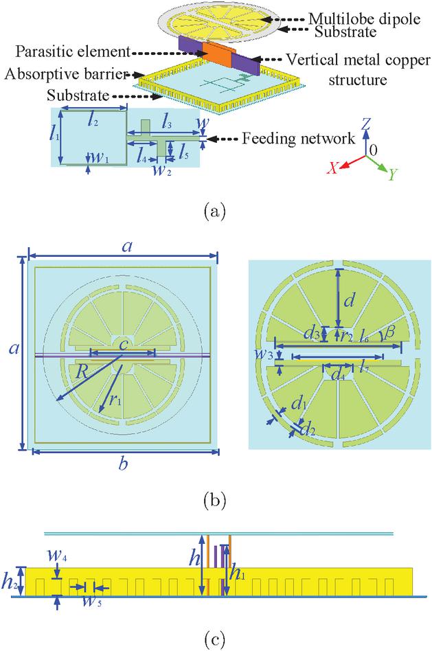
Figure 1 The configuration of the proposed antenna. (a) 3D perspective, (b) Top view, (c) Side view.
Table 1 Dimensional parameters for the antenna (Unit: mm)
| 50 | 46.6 | 12 | 14.6 | 16 | 3 | 3.5 |
| 1 | 0.25 | 2 | 1.1 | 2.6 | 1 | 25 |
| 18 | 16.6 | 21 | 14.2 | 11.5 | 1 | 0.87 |
| 2.7 | 6 | 2.6 | 30 | 8.3 | 6 | 3.7 |
2 ANTENNA DESIGN AND OPTIMIZATION
2.1 Antenna configuration
As illustrated in Fig. 1, the antenna adopts Rogers 4035 with a thickness of 0.254 mm for both upper and lower substrates, vertical parasitic plates, and surrounding isolation walls, with two copper blocks of 0.34 mm thickness placed between the parasitic plates. The antenna adopts a coupled feeding method, featuring a Y-shaped broadband feeding network on the substrate bottom plane with multi-branch configuration. The semicircular radiating dipoles on the upper substrate are split into several radiating lobes. Two semi-circular-rectangular dual-mode coupling structures are located between the two dipoles. The dimensional parameters of the antenna are summarized in Table 1.
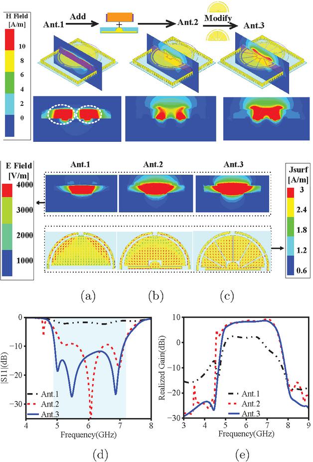
Figure 2 (a) Magnetic Field, Electric Field and Current Field of Ant. 1, (b) Ant. 2, (c) Ant. 3 at 5.5Hz, (d) S11, (e) Realized gain.
2.2 Antenna design procedure
As can be seen from Fig. 2 (a), a classic three-layer configuration is adopted in Ant.1, composed of a substrate, patch, and supporting metal block. The current exhibits a multidirectional distribution. According to the Maxwell-Ampere law, when the current density J is spatially dispersed with inconsistent directions, it generates weak and scattered magnetic field H in specific areas. The reverse current causes the magnetic field components to cancel out, as shown in Ant.1 in Fig. 2. Ampere’s circuital law indicates that curved current fields produce closed magnetic flux lines. The independence of current distribution reduces the effective value of loop integration, and the dispersed magnetic field prevents radiation energy from being concentrated. Combining the Poynting vector formula , and gain equation , when the input power remains constant, the instability of the electric and magnetic fields reduces the Poynting vector, resulting in a decrease in bandwidth gain, which causes very low gain across the frequency band and the absence of distinct radiation nulls. To address the performance limitations of Ant.1 and mitigate the effects of closed magnetic flux lines, magnetic flux control technology is employed. Vertical parasitic plates are added to the metal block, and rectangular slots are etched into the upper semicircular radiating patch, thereby expanding the radiation coverage. Simultaneously, a dual-mode coupled impedance matching structure is introduced around the slots using reverse current guidance technology. At 5.5 GHz, the magnetic field of antenna shows a tendency to break the closed magnetic flux lines and converge towards the radiation center of antenna, significantly improving the coupling effect of the antenna. As evident from Fig. 2 (e), the gain passband improved by over 6 dBi compared to Ant.1.
In addition, by concentrating the current and coupling the magnetic field, the dipole is etched into six 30∘ lobes, and an electromagnetic shielding isolation wall is added, as shown in Fig. 2 (c), resulting in a bandwidth greater than 36%, a peak gain of 8.9 dBi, and out-of-band suppression levels exceeding 32 dBi and 33 dBi.
2.3 Analysis of dual-mode coupling
To optimize antenna coupling modes, this study leverages current vector distribution. As shown in Fig. [fig.3]3 (a), the radiation patch of Ant A features a rectangular monopole shape, where the currents flow without concentration or directionality. This results in a dispersed current pattern that fails to effectively focus the radiation, leading to insufficient out-of-band suppression, as demonstrated in Fig. [fig.3]3 (c). Ant B adopts a rectangular-rectangular monopole composite impedance matching coupling structure, the current on the coupling element shows obvious reverse concentration and dispersion trends, a stronger radiation direction is formed, where the main radiation wave of antenna is concentrated within a relatively narrow range, significantly enhancing out-of-band suppression. Ant C further implements semi-circular-rectangular dual-mode aggregated coupling, with strong current distributed around the coupling element. With concentrated flow paths, the strong current distribution is enhanced, leading to a further reduction in high-frequency out-of-band suppression.
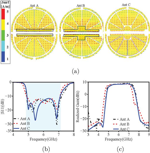
Figure 3 (a) The effect of different coupling forms on the antenna current at 5.5 GHz, (b) S11, (c) Realized Gain.
2.4 Transition from dipole to multi-lobe pattern
The study adopts a multi-lobe capacitive coupling strong current path topology reconstruction technology, which transforms irregular weak currents into regular and uniform strong current paths. As shown in Fig. [fig.4]4 (a), when the semicircular radiation patch is without a slot, the antenna current is primarily concentrated around the edges of the dipole patch with weak intensity, resulting in radiation energy being dispersed. Thus, both the impedance bandwidth and out-of-band suppression are suboptimal. In the 45∘ lobe configuration, dipoles are mainly concentrated on the lobe radiating patch adjacent to the dual-mode coupling structure, the current gathers on these segments while enhancing the radiation intensity, leading to significant improvements in both impedance bandwidth and out-of-band suppression at low frequency. When the lobe angle is 30∘, strong currents are primarily distributed on the first and second 30∘ lobe structures, which enhances the radiation effect in the main radiating region, impedance bandwidth is broadened and out-of-band suppression levels in the high-frequency range are improved. From the 3D gain patterns in Fig. [fig.4]4 (a), compared to the 30∘ and 45∘ lobe configurations, when the lobe angle is 0∘, the overall radiation performance of the antenna does not meet expectations, particularly in terms of the back lobe characteristics in the far-field radiation pattern, where significant deficiencies exist. In contrast, the 30∘ and 45∘ lobes demonstrate uniform radiation, with the 30∘ lobe configuration providing a wider and stronger radiation coverage area, as shown by the 3D gain in Fig. [fig.4]4 (a).
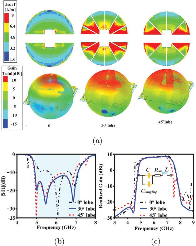
Figure 4 (a) The effect of different angle lobe structures on antenna current distribution and 3D Gain Total at 5.5 GHz, (b) S11, (c) Realized Gain and equivalent circuit.
In the antenna model, the insertion loss is equivalent to , the parasitic inductance of the intermediate layer is equivalent to , the parallel capacitance between the radiating patch and the ground plane is equivalent to , and the gap coupling capacitance between multi-lobe elements is equivalent to , as illustrated in Fig. [fig.4]4 (c). When the patch path is extended, the gap coupling equivalent capacitance increases. According to equation (1), since the high-frequency resonance frequencies exhibit strong fringe coupling effects, the increase in inductance leads to a decrease in the resonant frequency. In summary, by altering the distribution path of the current, the current concentration area is optimized. The dipoles of the antenna are divided into lobes, the radiation directionality and out-of-band suppression performance are optimized and the current distribution is optimized by controlling the lobe angle.
| (1) |
2.5 Generation of radiation nulls and analysis of isolation walls
To analyze the generation of radiation nulls and the role of the isolation walls of antenna, the current distribution vector diagrams at the null frequencies are shown in Fig. [fig.5]5. From Fig. [fig.5]5 (a), it can be observed that at frequencies of 4.3 GHz and 8.1 GHz, the dual-mode coupling and the copper structure exhibit symmetrical and oppositely directed current distributions. The cancellation of the magnetic fields leads to radiation nulls on both sides of the passband. As illustrated in Fig. [fig.5]5 (b), after the introduction of the isolation walls, the electromagnetic shielding effect significantly reduces the spread of electric fields and currents. The increased current density enhances polarization consistency, concentrates the radiation pattern, and cross-polarization levels are reduced, as demonstrated in Fig. [fig.5]5 (c) and Fig. [fig.5]5 (d). Therefore, the addition of isolation walls can suppress the diffusion of electric fields in ineffective directions, reducing radiation dispersion. This concentrates the electric field energy in specific regions, radiation directivity is improved and out-of-band suppression performance is enhanced.
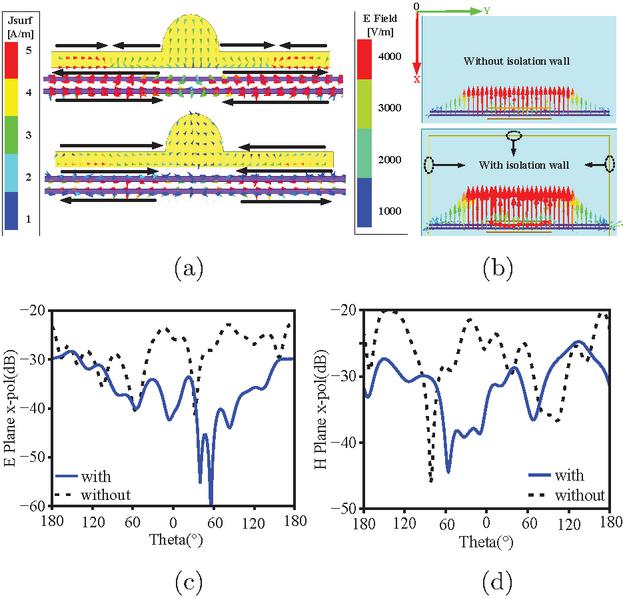
Figure 5 (a) Current vector distribution of the dual-mode dipole and copper structures at frequencies of 4.3GHz and 8.1GHz, (b) The effect of with and without isolation wall on the electric field distribution at 5.5 GHz, (c)-(d) The effect of the isolation wall on the cross-polarization in both the E plane and H plane at 5.5 GHz.
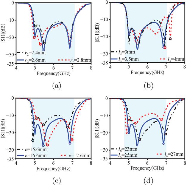
Figure 6 The effect of different parameters on the left and right resonance frequencies: (a) , (b) , (c) , (d) .
3 PARAMETRIC ANALYSIS
In order to better assess the overall performance of the antenna, the parameters in Fig. [fig.6]6 reveal the impact of key parameters on antenna performance. At low frequencies, the current flows along the expanded path of the main radiating structure. Increasing the radius of the coupling element extends the antenna’s equivalent electrical length, which leads to a reduction in low-frequency resonance, while leaving high-frequency currents unaffected. The branch of the feeding network is only 3.5 mm, much smaller than the quarter wavelength at low-frequency resonance. Therefore, adjusting the branch length shifts the high-frequency resonance without affecting the low- and mid-frequency points.
When the length of the parasitic element increases, all resonance points in the S-parameters shift toward higher frequencies. However, as continues to increase, the resonance peak value first decreases and then increases, while minimum value of the high-frequency resonance first decreases, then returns to its original state. When increasing the rectangular element length in the dual-mode structure, all resonance points shift toward lower frequencies, with the low-frequency resonance point first decreasing and then increasing. In summary, the resonance frequency and impedance bandwidth of antenna can be effectively tuned by adjusting parameters , , , and . The optimal performance occurs when mm, mm, mm, and mm and the impedance bandwidth of antenna reaches over 36%.
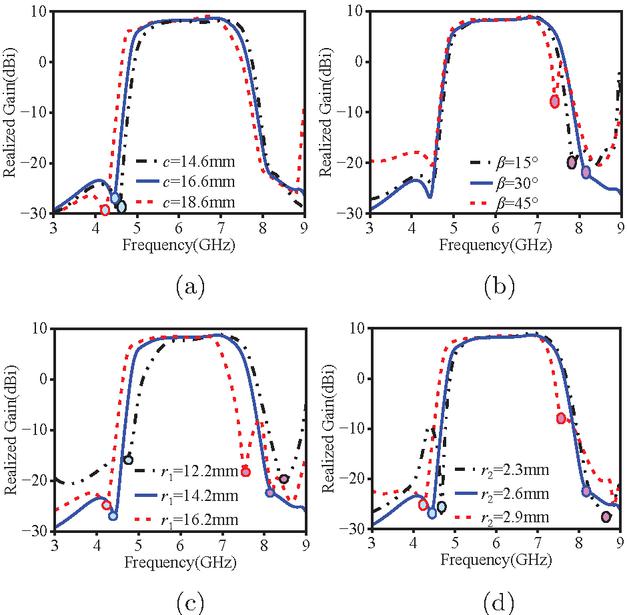
Figure 7 The effect of different parameters on the radiation zero points: (a) , (b) , (c) , (d) .
Since radiation nulls are a crucial feature of filtering antennas, this study conducts a comparative analysis of key parameters that influence radiation nulls, as shown in Fig. [fig.7]7. The parasitic elements and radiating patches on the upper substrate are the primary radiating structures contributing to this effect. Therefore, changes in their shape, size, and layout play a dominant role in determining the position and number of radiation nulls. As shown in Figs. [fig.7]7 (a–b), by adjusting the length of the parasitic elements, the petal angles of the multi-lobe dipole can be used to regulate the low-frequency and high-frequency radiation nulls, respectively. Furthermore, the radius of the semicircle on the upper patch and in the dual-shape coupler can be used to adjust radiation nulls position on both sides of the passband. When increasing and , combined with equation (1), the increased electrical length shifts both high- and low-frequency radiation nulls toward lower frequencies, as demonstrated in Figs. [fig.7]7 (c–d). Therefore, by adjusting these parameters properly, the distribution of radiation nulls within the operating frequency band of antenna can be controlled effectively. This also further enhances the out-of-band suppression and radiation directionality, thereby improving the overall performance of the antenna.
4 RESULTS AND DISCUSSION
To validate the feasibility of the experimental results, the antenna is fabricated and tested to validate its performance. The simulation and measurement results are shown in Fig. [fig.8]8. The insertion loss remains stable within the 5–7 GHz operating frequency range. The measured gain peak reaches 9.5 dBi, with a deviation of less than 0.6 dBi from the simulation results, validating the accuracy of the model. The overall radiation efficiency is consistently maintained above 90%, with particularly high efficiency between 5–7 GHz. However, the processing tolerance of the dielectric substrate and manufacturing error in the coupling capacitance cause a slight shift in the resonant point. The impedance bandwidth is still consistent with the simulation. These results show the high degree of agreement between the measured and simulated data.
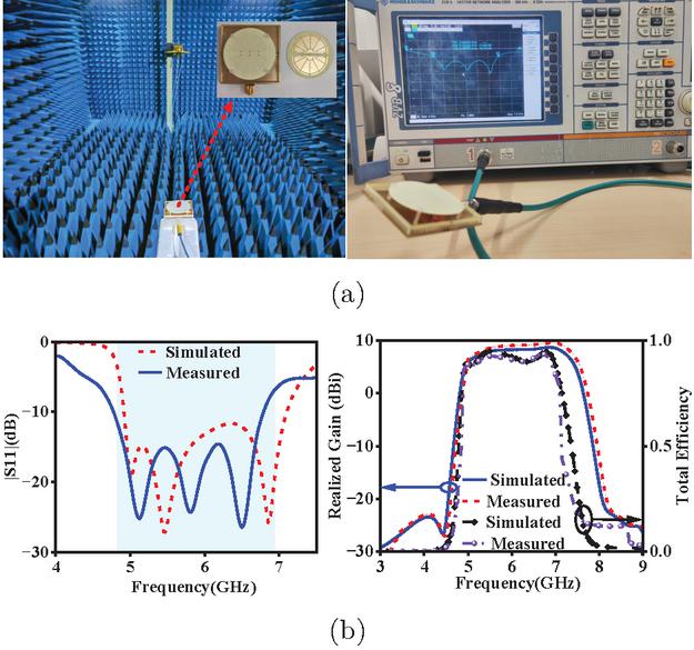
Figure 8 (a) Testing environment of proposed antenna, (b) Comparison of simulated and measured results.
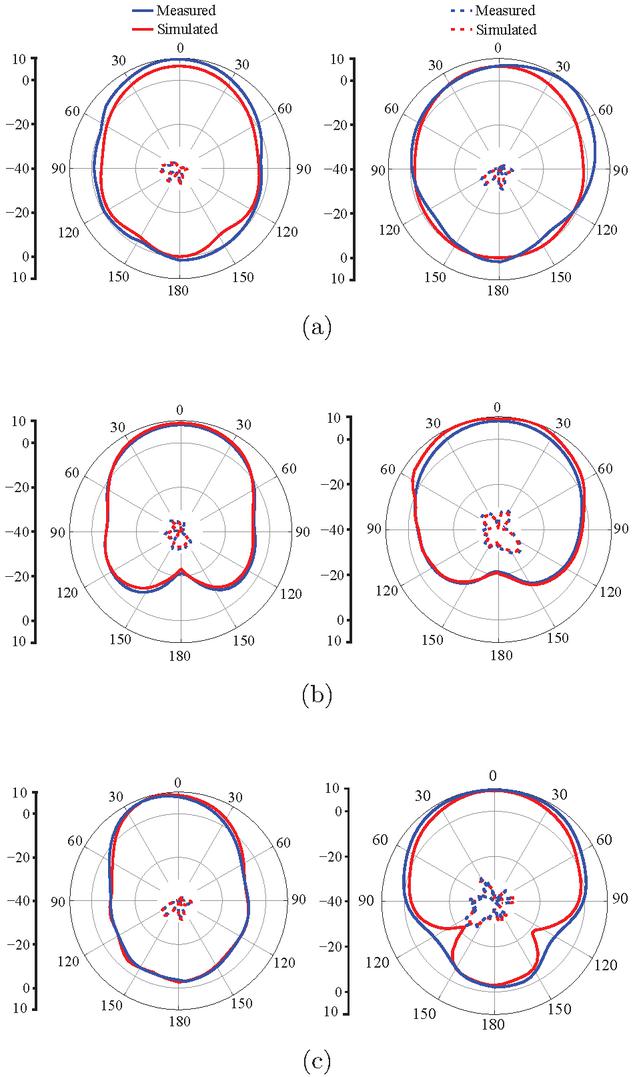
Figure 9 Simulated and measured radiation patterns of the antenna at different frequencies: (a) at 5 GHz, (b) at 5.5 GHz, (c) at 6.9 GHz.
To better understand the distribution characteristics of the radiation and reception capability of antenna in electromagnetic waves, Fig. [fig.9]9 presents the comparative radiation patterns in both the yoz-plane and xoy-plane, showing a strong agreement between the measured data and the simulated data in the same polarization direction. At 5 GHz and 5.5 GHz, the main polarization outperforms cross-polarization by 35 dB and 30 dB, respectively. The cross-polarization in the yoz-plane stays below 30 dB. At 6.9 GHz, the main and cross-polarization difference slightly decreases. The front-to-back ratio exceeds 13 dB at the high-frequency resonant point, showing stable and favorable radiation performance overall. At 5 GHz and 5.5 GHz, the main polarization outperforms cross-polarization by 35 dB and 30 dB, respectively. The cross-polarization in the yoz-plane stays below 30 dB. At 6.9 GHz, the main and cross-polarization difference slightly decreases. The front-to-back ratio exceeds 13 dB at the high-frequency resonant point, showing stable and favorable radiation performance overall.
Table 2 Comparison of the designed antenna with similar-band antennas from other literature
| Ref. | Freq | BW | Gain | OOBS | x-pol |
| (GHz) | (%) | (dBi) | (dB) | E/H (dBi) | |
| [13] | 2.29–2.69 | 16.10 | 9.60 | 15 | 25/20 |
| 17 | |||||
| [14] | 1.11–1.39 | 22.40 | 4.50 | 13 | 18/19 |
| 12 | |||||
| [15] | 9.80–10.20 | 4.00 | 8.50 | 12 | 25/25 |
| 13 | |||||
| [16] | 3.19–3.85 | 18.80 | 9.50 | 7 | 20/18 |
| 9 | |||||
| [17] | 4.45–5.52 | 21.50 | 4.80 | 16 | 20/16 |
| 19 | |||||
| [18] | 3.28–3.79 | 14.40 | 11.14 | 18 | 22/21 |
| 18 | |||||
| [19] | 8.50–10.00 | 16.20 | 8.50 | 12 | 20/20 |
| 19 | |||||
| [20] | 4.28–5.34 | 22.04 | 10.40 | 15 | 22/20 |
| 16 | |||||
| This work | 7.92–7.10 | 36.30 | 8.90 | 32 | 30/26 |
| 33 | |||||
| BW represents bandwidth, OOBS represents out-of-band suppression, x-pol represents cross-pol. | |||||
Table [Table 2.]2 provides a detailed comparison of the performance of the proposed antenna with other antennas in similar frequency bands. The comparison data shows that the antenna designed in this study exhibits significant advantages in multiple key performance metrics.
In terms of operating bandwidth, the antenna demonstrates a impedance bandwidth from 4.92 GHz to 7.10 GHz. In comparison to all the references in Table [Table 2.]2, this antenna employs current-control technology and isolation wall electromagnetic shielding technology, resulting in higher out-of-band suppression and lower cross-polarization. In contrast to references [14, 15, 17], and [19], the proposed antenna demonstrates a more stable high gain.
5 CONCLUSION
A double-layered filtering antenna based on a multi-lobe dipole structure is proposed in this study. A symmetrical upper-lower dielectric substrate configuration with integrated parasitic elements is featured in the antenna, combined with a distinctive semi-circular-rectangular composite impedance matching structure. The radiating dipole is decomposed into multiple monopoles through distributed current control technology. An electromagnetic shielding wall with etched rectangular apertures is incorporated, significantly improving the radiation performance of the antenna. The test results show that the antenna performs well in the 5.5 GHz frequency band, with an impedance bandwidth of 36%, a peak gain of 8.9 dBi, cross-polarization levels in the E-plane and H-plane below 30 dB and 26 dB, respectively, and an out-of-band suppression level greater than 32 dB.
ACKNOWLEDGMENT
This paper is supported by Yunnan Fundamental Research project [202401AT070351, 202401AT070376, 202301AV070003], Yunnan Key Laboratory of Computer Technologies Application Open Fund, the Natural Science Foundation of China [61971208], Yunnan Young Top Talents of Ten Thousands Plan [Shen Tao, Yunren Social Development No. 2018 73], College personnel training project [202101BE070001-008], and partially by the Major Science and Technology Projects in Yunnan Province under Grant [202302AG050009 and 202202AD080013].
References
[1] S. Wang, F. Fan, R. Gomez-Garcia, L. Yang, Y. Li, and S.-W. Wong, “A planar absorptive-branch-loaded quasi-Yagi antenna with filtering capability, and flat gain,” IEEE Antennas Wireless Propag. Lett., vol. 20, no. 9, pp. 1626–1630, Sep. 2021.
[2] D. Li, C. Yang, L. Shi, Y. Liu, Q. Chen, and N. Shinohara, “A high-gain filtering quasi-yagi antenna based on compressed third-order mode dipole,” IEEE Antennas Wireless Propag. Lett., vol.23, no. 10, pp. 2860–2864, Oct. 2024.
[3] J. Deng, S. Hou, L. Zhao, and L. Guo, “A reconfigurable filtering antenna with integrated bandpass filters for UWB/WLAN applications,” IEEE Trans Antennas Propag., vol. 66, no. 1, pp. 401–404, Jan. 2018.
[4] O. A. Iupikov, J.-R. Perez-Cisneros, P. Meyer, D. Akesson, R. Maaskant, and K. Buisman, “A cavity-backed patch antenna with distributed multi-port feeding, enabling efficient integration with Doherty power amplifier and band-pass filter,” IEEE Trans Antennas Propag., vol. 69, no. 8, pp. 4412–4422, Aug. 2021.
[5] G. Cheng, J. Zhou, B. Huang, L. Yang, and Z. Huang, “Compact low-profile wideband filtering antenna without additional filtering structure,” IEEE Antennas Wireless Propag. Lett., vol. 22, no. 10, pp. 2477–2481, Oct. 2023.
[6] X. Liu, K. Ning, S. Xue, L. Ge, K. W. Leung, and J.-F. Mao, “Printed filtering dipole antenna with compact size and high selectivity,” IEEE Trans Antennas Propag., vol. 72, no. 3, pp. 2355–2367, March 2024.
[7] D. Zhao, F. Lin, H. Sun, and X. Y. Zhang, “A miniaturized dual-band SIW filtering antenna with improved out-of-band suppression,” IEEE Trans Antennas Propag., vol. 70, no. 1, pp. 126–134, Jan. 2022.
[8] G. Liu, P. F. Hu, G. D. Su, and Y. M. Pan, “Bandwidth and gain enhancement of a single-layer filtering patch antenna using reshaped TM mode,” IEEE Antennas Wireless Propag. Lett., vol. 23, no. 1, pp. 314–318, Jan. 2024.
[9] N. Yan, C. Wang, Y. Luo, and K. Ma, “A low-profile broadband filtering dielectric resonator antenna based on SISL with the improvement of suppression level,” IEEE Open J. Antennas Propag., vol. 5, no. 2, pp. 430–436, Apr. 2024.
[10] H. L. Yang, H. T. Liu, X. P. Li, Y. P. Li, S. Z. Wang, J. S. Zhang, C. H. Wang, and Y. Fang, “A wideband high front-to-back ratio directional filtering slot antenna and its application in MIMO terminals,” Applied Computational Electromagnetics Society (ACES) Journal, vol. 39, no. 11, pp. 980–986, Nov. 2024.
[11] S. J. Yan, C. Q. Zhang, Q. Chen, and M. S. Tong, “A novel compact filtering antenna for 5.0-GHz WLAN communication system,” Applied Computational Electromagnetics Society (ACES) Journal, vol. 37, no. 9, pp. 996–1004, Sep. 2022.
[12] R. Hou, J. Ren, Y.-T. Liu, Y.-M. Cai, J. Wang, and Y. Yin, “Broadband magnetoelectric dipole filtering antenna for 5G application,” IEEE Antennas Wireless Propag. Lett., vol. 22, no. 3, pp. 497–501, Mar. 2023.
[13] L. Li, H. D. Xiong, W. Y. Wu, A. B. Fu, and J. Y. Han, “A T-shaped strips loaded wideband filtering patch antenna with high selectivity,” IEEE Antennas Wireless Propag. Lett., vol. 23, no. 1, pp. 89–93, Jan. 2024.
[14] X. Chen, X. Fang, Z. Wu, and L. Zhu, “A pattern-reconfigurable, compact, wideband filtering directive dipole antenna enabled with mixed couplings,” IEEE Antennas Wireless Propag. Lett., vol. 24, no. 1, pp. 237–241, Jan. 2025.
[15] K.-R. Xiang, F.-C. Chen, and Q.-X. Chu, “High selectivity and high gain X-band waveguide filtering antenna based on triple-mode resonator,” IEEE Trans Antennas Propag., vol. 69, no. 10, pp. 6953–6938, Oct. 2021.
[16] H. Yuan, F.-C. Chen, and Q.-X. Chu, “A wideband and high gain dual-polarized filtering antenna based on multiple patches,” IEEE Trans Antennas Propag., vol. 70, no. 10, pp. 9843–9848, Oct. 2022.
[17] B.-J. Chen, X.-S. Yang, and B.-Z. Wang, “A compact high-selectivity wideband filtering antenna with multipath coupling structure,” IEEE Antennas Wireless Propag. Lett., vol. 21, no. 8, pp. 1654–1658, Aug. 2022.
[18] T. Wang, N. Yan, M. Tian, Y. Luo, and K. Ma, “A low-cost high-gain filtering patch antenna with enhanced frequency selectivity based on SISL for 5G application,” IEEE Antennas Wireless Propag. Lett., vol. 21, no. 9, pp. 1772–1776, Sep. 2022.
[19] Y.-H. Ke, L.-L. Yang, Y.-Y. Zhu, J. Wang, and J.-X. Chen, “Filtering quasi-Yagi strip-loaded DRR antenna with enhanced gain and selectivity by metamaterial,” IEEE Access, vol. 9, pp. 31755–31761, 2021.
[20] M. Tian, N. Yan, Y. Luo, and K. Ma, “A low-cost high-gain filtering patch antenna using SISL technology for 5G application,” IEEE Antennas Wireless Propag. Lett., vol. 20, no. 12, pp. 2270–2274, Dec. 2021.
Biographies

Jiangling Dou was born in 1985 in Jiangsu Province, China. She received her Ph.D. degree in Electromagnetic Fields and Microwave Technology from Southeast University in 2018. She is currently working at Kunming University of Science and Technology. Her research interests include electromagnetic field theory and applications.

Yinsu Yuan was born in 1997 in Qujing, Yunnan, China. She is currently pursuing a master’s degree at Kunming University of Science and Technology, focusing on the design of miniaturized filtering antennas.

Tao Shen (Senior Member, IEEE) earned his Ph.D. from the Illinois Institute of Technology in Chicago, Illinois, USA, in 2013. Presently, he holds the position of President at Yunnan Vocational and Technical College of Mechanical and Electrical Engineering. Dr. Shen has contributed to over 20 publications in prestigious SCIE-indexed journals and leading international conferences within his research domains. His areas of expertise include image processing, artificial intelligence, and the Internet of Energy.

Jian Song (Member, IEEE) obtained his Bachelor of Engineering degree in Electronics Information Engineering from Jiangxi University of Science and Technology in Ganzhou, China. He later earned his Ph.D. in Electromagnetic Fields and Microwave Technology from the University of Electronic Science and Technology of China in Chengdu in 2015. Between 2015 and 2019, he served as an Algorithm Engineer at Huawei Technology Co., Ltd. in Shenzhen, China.
ACES JOURNAL, Vol. 41, No. 2, 194–202
DOI: 10.13052/2026.ACES.J.410211
© 2026 River Publishers