A Novel Approach for Early-Stage Breast Cancer Detection
Mohamed Behih1, Christophe Dumond2, Farid Bouttout1, and Tarek Fortaki3
1EAT Laboratory, Institute of Electronics and Telecommunications, University of Mohamed El Bachir El Ibrahimi, Bordj Bou Arreridj, Algeria, mohamed.behih@univ-bba.dz, f.bouttout@univ-bba.dz
2PRISME Institut, IUT of Chartres, University of Orleans, Orleans, France, christophe.dumond@univ-orleans.fr
3AE Laboratory, Departement of Electronics, University of Batna 2, Mostefa Ben Boulaïd, Batna 05000, Algeria, t.fortaki@univ-batna2.dz
Submitted On: August 02, 2025; Accepted On: February 01, 2026
Abstract
This paper presents a novel approach for early-stage breast cancer detection using only a single radiofrequency 3D antenna sensor operating in several frequency bands below Ultra-Wide Band (UWB) frequencies. To this end, an innovative Inverted-F Antenna with Short Circuit-Like (IFA-SCL) is proposed, and the breast to be examined is fully placed inside this antenna between the radiating element and the ground plane. The designed and simulated antenna operates in the two frequency bands (902.8–928.0 MHz and 2.400–2.4835 GHz) of the Industrial, Scientific, and Medical (ISM) bands. After examination of the two patient breasts and by comparison of the antenna’s performances considering the return loss (S dB), tumor presence is detected when the resonance frequencies that cover the operating frequency bands corresponding to an unhealthy breast, are shifted to higher frequencies and the corresponding magnitudes are changed. A spherical shape model of the female breast tissues is created for designing and simulating antenna and tumor detection performances. Also, to test the practicality of the proposed method and detail the tumor detection performances with breast variability, three tests are performed using side-set and teardrop shape breasts. The present approach demonstrates great potential to become a new way for early-stage breast cancer detection, both quickly and with high efficiency. The proposed method, and thus the designed multi-band 3D antenna sensor, exhibits the capability to detect a tumor of spherical shape, of radius only 1 mm and embedded deeply in the breast. Furthermore, it is able to sense tumor presence even with breasts of various sizes and shapes. The patient’s safety is ensured by adhering to Specific Absorption Rate (SAR) limits.
Keywords: 3D antenna, breast cancer detection, dual-band antenna, ISM bands, tumor..
1 INTRODUCTION
Cancerous or malignant tissues are produced due to uncontrolled cell division due to genetic mutations which disrupts the natural cell cycle regulation. Breast cancer is a malignant tumor that originates in the glandular epithelium of the breast and can spread to other parts of the breast. It has emerged as a serious health concern worldwide and the most common cancer among women [1]. For both sexes, breast cancer represents the second leading cause of cancer-related deaths after lung cancer [2, 3, 4, 5, 6].
The process of early-stage breast cancer detection is crucial for reducing its deployment in the breast, mortality rates, and improving treatment outcomes. It allows for timely intervention before the disease progresses to advanced stages [4, 7]. The extreme emphasis of early-stage breast cancer detection is reflected by the wide array of methods and strategies used for this objective, from traditional imaging and clinical assessment to emerging molecular, computational, and biomarker-based methods [7, 8, 9]. The most common imaging-based methods for breast tumor detection are X-ray mammography imaging [9, 10, 11], ultrasound imaging [1, 12, 13], magnetic resonance imaging [1, 12, 13], and Microwave Breast Imaging (MWBI) in its two strategies of tomography and radar-based [1, 5, 10, 12, 14, 15, 16, 17].
X-ray mammography imaging is a widely used screening tool for breast cancer detection. It utilizes low-dose X-rays to image the breast and is effective for early-stage breast cancer detection. However, it can be uncomfortable, it implies exposure to ionizing radiation, it is less effective for dense breasts, and it leads to false-positive and false-negative results [11].
The ultrasound imaging technique uses sound waves to create images of the breast. It is often used as a complementary process to the X-ray mammograms, especially in dense breasts. Ultrasounds are not able to distinguish between malignant and benign tumors, and they produce low-resolution images [1, 12, 13].
Magnetic resonance imaging uses magnetic fields and radio waves to produce detailed images; it provides high sensitivity in detecting breast cancer, especially in dense breast tissue. This technique is characterized by high cost and variable specificity, leading to more false-positives and a lack of standardized interpretation criteria and protocols [1, 12, 13].
The microwave tomography technique operates by illuminating the breast with low-power microwave signals in the 0.3–10 GHz range using multiple antennas arranged around the breast. The scattered fields are collected, and inverse algorithms reconstruct images that reveal spatial distributions of dielectric permittivity and conductivity. Malignant tissues, due to their higher water and ionic content, show higher permittivity and conductivity, enabling tumor detection. While microwave tomography shows promise as a non-ionizing, patient-friendly technique for breast cancer imaging, its spatial resolution, sensitivity for small or deep-seated tumors, susceptibility to tissue heterogeneity and coupling artifacts, and slow computational performance remain key hurdles for early-stage breast cancer detection. Furthermore, insufficient large-scale clinical validation and lack of standardization limit its transition from research prototype to routine clinical tool [1, 12].
The radar-based MWBI uses low-power and short-duration Ultra-Wide Band (UWB) pulses to scan the breast tissue. A set of antennas placed around the breast is used for both power transmitting, and back-scattered energy collecting. Signals corresponding to the collected power are used to produce a 3D image of the scanned breast [1, 12]. The radar-based MWBI senses the dielectric properties changes between normal and abnormal breast tissues to detect and locate the breast tumors. It is widely applied for breast tumor detection; in fact, it allows the obtaining of high-contrast 3D images using non-ionizing radiation and without breast compression. Radar-based MWBI systems avoid complex computational challenges associated with microwave tomography. However, this method requires a complex and high-cost system; the use of multiple antennas and feeds creates a complex system that can be difficult to manage. This complexity can lead to mutual coupling between antennas, resulting in low resolution and accuracy. In addition, used antennas must be arranged in ring or arc geometries around the pendulant breast [5].
Comparing the various methods and techniques used for breast cancer detection summarized above, it appears that the radar-based MWBI method is most convivial for breast cancer detection; in fact, it presents compelling advantages over X-ray mammography, ultrasound, and MRI, both in terms of underlying physical principles and practical clinical application. The key behind this success is the antenna and its high sensing capability. Unlike the complexity and high cost related to radar-based MWBI systems, their antennas multiplicity, and the accompanied problems and inconvenience as discussed above, using a single antenna with a simple system and procedure for breast cancer detection is very interesting.
Radiofrequency antenna technology is widely used and practiced for various healthcare purposes, e.g., stimulation [18], hyperthermia and tumor ablation [19] for therapeutic ends, biotelemetry [20], wireless power transfer for implants [21], and early-stage breast cancer detection [22]. Herein, the dielectric properties of human body tissues (adding to those abnormal ones) are the keystone.
Radiofrequency antennas operating below UWB frequencies, i.e., below 3.1 GHz, confer several compelling advantages for healthcare applications; electromagnetic waves radiated by such antennas exhibit reduced dielectric loss and greater penetration depth in human body tissues compared to UWB and higher bands. In addition, several frequency bands and services are allocated and reserved for biomedical and healthcare purposes: frequency bands 401–406 MHz of the medical device radiocommunications service, bands 433.1–434.8, 868.0–868.6, and 902.8–928.0 MHz and 2.400–2.4835 GHz of the Industrial, Scientific, and Medical (ISM) bands, and the bands 608–614 MHz, 1.395–1.400, and 1.427–1.432 GHz of the Wireless Medical Telemetry Service [20, 21]. Furthermore, operating at frequencies below UWB frequencies produces lower Specific Absorption Rate (SAR) for a given transmitted power, which reduces the risk of tissue heating and enables continuous or long-duration operation while keeping the SAR below regulatory thresholds.
Using antenna performances in the below UWB frequencies for early-stage breast cancer detection is not widely reported in the literature. Furthermore, proposed and suggested antennas for this purpose are generally planar and functional in a single band [23, 24, 25, 26, 27]. Using these antennas, resonance frequency shifting, reflection coefficient magnitude variation, and impedance bandwidth displacement and changing have been used for tumor detection. Using multi-band antennas allows one to obtain more accurate diagnostic results; a multitude of operating frequency bands increases the antenna sensing capability to detect even minor variation in dielectric properties of breast tissues and, thus, to detect the tumor presence even with the smallest size.
In [23], a single-band and planar array-antenna sensor is proposed for early-stage breast cancer detection; the frequency band of operability is around 2 GHz. This proposed antenna processes a high sensitivity for breast cancer detection, but the sensor operational frequency band is not reserved for medical and healthcare purposes.
In [24], a miniaturized, wearable, planar, and triple-band microstrip antenna is carried out for early-stage breast cancer detection. Operating frequency bands are ISM 2.45 GHz, and around the frequencies of 5.5 and 6.1 GHz. The suggested antenna can’t detect breast tumors smaller than 2 mm in radius, and only at a maximum depth of 10 mm using imaging.
A planar patch antenna operating in the frequency band of ISM 2.45 GHz has been designed and simulated for early-stage breast cancer detection in [25]. Only tumors of a radius of 6 mm at least can be detected. Furthermore, the tumor depth influence on detection capability is not discussed.
The planar monopole antenna suggested in [26] for breast cancer detection operates in the frequency band of 1.9–2.1 GHz. The tumor model used simulates a radius of 8 mm. Furthermore, the operating frequency band is not allocated for biomedical and healthcare applications.
Reference [27] describes a metasurface-based planar microstrip array antenna operational in the frequency band of ISM 2.4 GHz. The tumor examined is of a diameter of 1.5 mm.
This work aims to propose a novel and promising approach for early-stage breast cancer detection using non-ionizing electromagnetic waves. It is non-invasive, low-cost, safe, and comfortable for the patient, and sensitive for small and deep-seated tumors. The proposed approach senses tumor presence using performances of an innovative single radiofrequency antenna. The designed and simulated antenna has the following features:
(1) The proposed antenna is of 3D structure, and the breast to be examined is placed inside this antenna, i.e., between the radiating element and the ground plane. By this placing manner, the antenna’s performances are strongly linked to any change in dielectric properties of breast tissues, i.e., to any tumor presence. Dielectric properties changing is sensed in both operating frequency bands of ISM 915 MHz and 2.45 GHz based on resonance frequency shifting and the corresponding reflection coefficient magnitude increasing/decreasing.
(2) The designed and simulated antenna sensor is a patch antenna modified by slots inserted in both the radiating element and the short-circuit-like, and open-end slot inserted in the ground plane. The dimensions and the solidity of the designed antenna allow us to facilitate and accelerate the examination procedure with a large degree of freedom for the patient. It may be used sitting, standing, or lying down.
(3) Two frequency bands are targeted for the antenna’s operability to increase the antenna sensor capability for smallest tumor detection in any region in the breast; if a tumor presence is not marked clearly in an operating frequency band, it will be sensed more clearly with the antenna’s performances in the other operating frequency band. Furthermore, these two frequency bands are reserved and used for medical applications and covered with high impedance matching for each of them. In addition, these two frequency bands are located below the UWB frequencies, which further ensures patient safety, as they are associated with relatively lower losses through the human body tissues.
(4) A spherical shape phantom model of the human female breast is used in the design and simulation of the 3D antenna sensor and in tumor detection performances. The applied dielectric properties of healthy breast tissues and of tumors are based on empirical, approved, and most cited models.
(5) Using a phantom model of the frontal torso and a realistic model of the female human body of VHP-Female version 2.1 [28], the practicality of the proposed method is performed, and simulation outcomes show promise for breast cancer detection using only a single multi-band 3D antenna sensor.
The remainder of this paper is organized as follows. In section 2, the breast phantom model, proposed antenna design, and simulation process are presented. In section 3, breast cancer detection performances are detailed. Section 4 shows practical testing by simulation of the proposed method considering breast variability. In section 5, SAR restrictions adherence is described and shown. In section 6, a conclusion for summarizing the main obtained results is given.
2 BREAST MODELING AND ANTENNA DESIGN
As in all electromagnetic problems, designing and simulating antennas for any purpose is based on solving of Maxwell’s equations. Most antenna problems involve complex model geometries and solving these leads to a set of equations unsolvable analytically, e.g., via variable separation and Green’s functions. In the problem solved in this paper, the model geometry becomes more and more complex with the using of the three various biological structures of the spherical model of the human female breast, the phantom model of the frontal side of the middle part of the human body, and female human body the realistic model of VHP-Female version 2.1.
Complex electromagnetic problems solving like in the case of the problems solved in this paper requires the use of numerical methods like the finite element method (FEM), used for the design and the simulation of the proposed approach. Herein, the 3D FEM solver within Ansys HFSS software is employed. This package is considered as one of the most powerful tools used for complex electromagnetic problems treatment. To create and solve an electromagnetic problem in HFSS, next steps are performed: creating the model of the problem to be solved, assign boundaries and excitation, set up the solution, solving the problem, and finally post-process the results. Using HFSS, the problem solving implies the automatically subdividing procedure of the whole model geometry into many smaller subsections of tetrahedron shape. The entire collection of these tetrahedrons represents the mesh of the problem. The obtained initial mesh is refined automatically and iteratively using adaptative meshing, focusing on high-error areas for accurate results until a highly precise outcome is met. In all design and simulation processes realized in this paper, the electromagnetic fields within the model mesh elements are solved using first-order basis functions for better accuracy with fewer elements, leading to faster convergence and reduced computational cost.
2.1 Breast phantom model
For numerical electromagnetic computational purposes such as breast cancer detection, the realistic human breast can be modeled by layered phantom models; each layer simulates a particular breast tissue, its shape, dimensions, thickness, and dielectric properties. A healthy breast is a heterogeneous organ constituted of skin, fat, glandular/fibro-glandular tissues, and a nipple. For an adult woman, the breast is of average full diameter of around 114 mm, and may have various shapes, e.g., round, teardrop [29]. To present the proposed approach for breast cancer detection, the used 3D multi-layer phantom model (Brst_mdl.1) of a healthy female breast is represented in Fig. 1. In this model, skin, fat, and glandular tissue layers are shapes of concentrated half spheres and simulate radii of 55, 53, and 50 mm, respectively. The nipple is also modeled by a half-sphere with a radius of 6 mm.
Dielectric properties of breast tissues, like all human body tissues, are relative permittivity, r, and conductivity, . These two properties are highly frequency-dependent and given by the Cole-Cole empirical model [30].
2.2 IFA-SCL antenna design and simulation
The dual-band Inverted-F Antenna with Short Circuit-Like (IFA-SCL) antenna sensor designed in this work is tuned to operate in the two frequency bands of ISM 915 MHz and 2.45 GHz with enhanced impedance matching and impedance bandwidth as wide as possible. A 3D and a frontal view of the designed and simulated antenna are shown in Figs. 2 (a) and 2 (b), respectively. The healthy female breast phantom model is placed inside the 3D antenna. This antenna sensor is constituted of three parts, which are a shaped radiating element, a short circuit-like, and a modified ground plane. These antenna’s three parts are printed on a substrate, on the side of an internal vertical support, and under a superstrate of Cuflon dielectric material, respectively.
Cuflon is characterized by a relative permittivity r of 2.05, a loss tangent of 0.00045, and a dielectric thickness of 0.38 mm. The antenna feeding is ensured by a coaxial cable through a Sub-Miniature version A (SMA) connector with a characteristic impedance of 50 .
The shaped radiating element is shown in Fig. 3 (a), and its surficial size is mm2. The antenna feed is positioned at the origin of the coordinate system and away from the close edge of the radiating element by 50 mm along the x axis. The substrate corresponding to this radiating element possesses surficial dimensions of ( mm2. This radiating element is modified by the insertion of two meandered slots MS.I and MS.II.
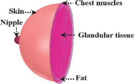
Figure 1 3D view of female breast multi-layer phantom model.
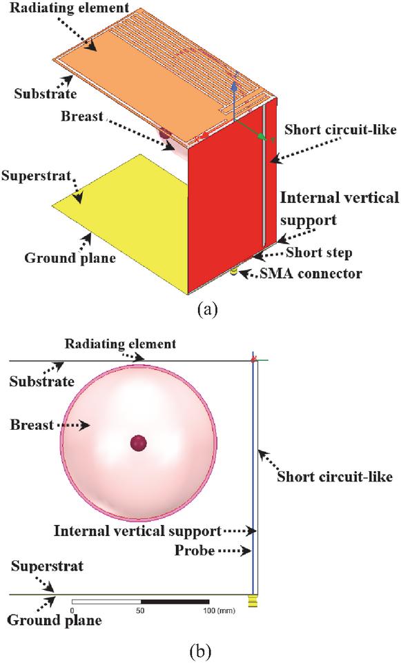
Figure 2 IFA-SCL antenna sensor structure: (a) 3D view and (b) frontal view.
The surficial dimensions of the five parts (MS.I_Prt.1 to MS.I_Prt.5) of the first meandered slot MS.I are (41.5 1.5), (2.5 11), (47 2), (1.5 8), and (48 2) mm2 for parts from Part.1 to Part.5, respectively. The element MS.I_Prt.1 is away from the close edge of the radiating element by 3 mm along the y axis. The element MS.I_Prt.5 branches out to five other slots (MS.I_ST.1 to MS.I_ST.5) in a saw teeth shape. These slots measure surficial dimensions of (2 152) mm2, and they are away from the close edges of the radiating element by 2, 12, 22, 32, and 42 mm along the y axes, respectively.
For the second meandered slot, i.e., MS.II, the length and width of its three parts (MS.II_Prt.1 to MS.II_Prt.3) are (50 2.5), (3 175), and (99 2) mm2, respectively. The element MS.II_Prt.3 is attached to four slots (MS.II_ST.1 to MS.II_ST.4) in saw teeth shape of dimensions of (2 152) mm2 for each of them. These four slots are away from the close edge of the radiating element by 7 mm for the slot MS.II_ST.1, 17 mm for the slot MS.II_ST.2, 27 mm for the slot MS.II_ST.3, and 37 mm for the slot MS.II_ST.4 along the x axis. The element MS.II_Prt.1 is distant from close edges of the radiating element by 5, and 2 mm along the x and y axes, respectively.
The short circuit-like is depicted in Fig. 3 (b). This antenna constituent measures surficial dimensions of (XSCL ZSCL) = (111 167.6) mm2. The length and the width of the slot inserted in this short circuit-like are 165 and 4 mm, respectively. Also, the surficial dimensions of the rectangular short step used to connect the short circuit-like to the ground plane are (11 2.4) mm2. The slot and the rectangular short step are away from the close edge of the short circuit-like by 14 and 30 mm along the x axis, respectively. The internal vertical support corresponding to the short circuit-like is to enforce the antenna solidity. Its dimensions are (XIVS Z mm2. Figure 3 (c) illustrates the ground plane and the corresponding superstrate. Their dimensions are (X mm2. The surficial dimensions of the open-end slot inserted to reformulate the ground plane are (44 2) mm2. This open-end slot is away from the close edge of the ground plane by 3.9 mm along the y axis.
The final structure of the IFA-SCL antenna is the outcome of the design process that can be summarized in three principal steps. The simulation is performed using the 3D full-wave software of High-Frequency Structure Simulator (HFSS), which is based on the finite element method to solve electromagnetic problems. Also, the simulation run-time is very high due to the heterogeneity of the breast phantom model, and also due to the large dimensions of the designed 3D antenna. Furthermore, this time increases from one design step to the next.
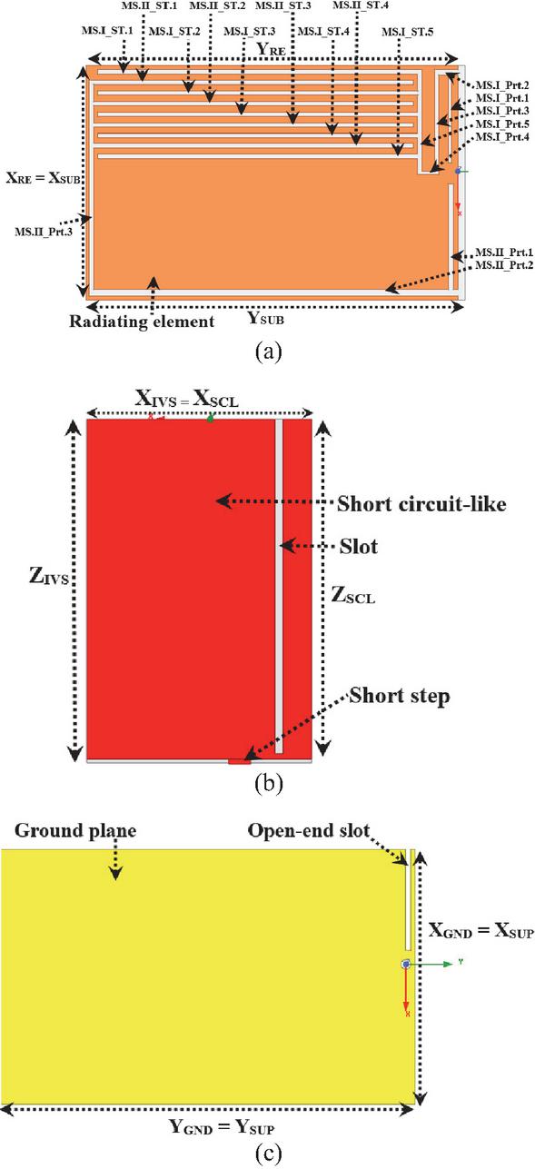
Figure 3 2D view of the designed 3D antenna sensor elements: (a) radiating element, (b) short circuit-like, and (c) ground plane.
Figure 4 shows the radiating element, the short circuit-like, and the ground plane structures issuing from successive design and simulation steps. To validate each step, the reflection coefficient representation is adopted as indicated by Fig. 5. The design and simulation steps are as follows:
First, using two Cuflon dielectric Printed Circuit Boards (PCBs) of size (111 180 0.38) mm3 and copper thickness of 18 m for each of them, a patch antenna with a full ground plane and rectangular radiating element is designed and simulated. The first PCB is used to print the radiating element; however, the second PCB is used to print the ground plane as depicted in Fig. 4 (a).
The radiating element is connected to a coax-feed via a SMA connector with a probe of full length of 170 mm and radius of 0.38 mm (Fig. 2 (b)), which yields a 3D patch antenna. The breast (Brst_mdl.1) to be examined is placed inside the antenna. The computed reflection coefficient that corresponds to this first step is represented by Fig. 5 (First step). In the frequency range of interest, i.e., from 0.85 to 2.8 GHz, three resonance frequencies are obtained at frequencies of 0.96 GHz, 1.76 GHz, and 2.64 GHz. For the lower resonance, it is close to the first targeted frequency band of ISM 915 MHz, but its impedance matching is not sufficient. The third resonance is close to the second targeted frequency band of ISM 2.45 GHz and presents a practical impedance matching. In the next design and simulation steps, these first and third resonance frequencies will be reduced and tuned to cover the two targeted frequency bands with enhanced impedance matching as possible.
Second, a short circuit-like is inserted in the antenna between the radiating element and the ground plane and connected to the ground plane by a rectangular short step. In addition, to enforce the solidity of the 3D antenna, the short circuit-like is printed on the side of an internal vertical support of Cuflon dielectric material. To reduce the first and third resonance frequencies obtained in the precedent design step, a rectangular slot is inserted in this short circuit-like as shown by Fig. 4 (b).
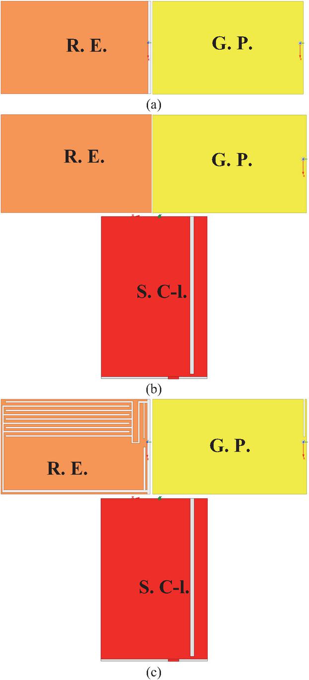
Figure 4 Design and simulation process steps: (a) first step, (b) second step, and (c) third and final step. R.E. Radiating element, G.P. Ground plane, S.C-l. Short circuit-like.
The reflection coefficient corresponding to this step is represented by Fig. 5 (Second step). A shift to lower frequencies is obtained for the first resonance frequency, and the first targeted frequency band of ISM 915 MHz is partially covered with a practical impedance matching. Furthermore, the third resonance frequency obtained in the first step of this design is also reduced, leading to covering the second targeted frequency band of ISM 2.45 GHz with a satisfactory impedance matching.
Finally, to cover the two targeted frequency bands with impedance bandwidth as wide as possible and improved impedance matching as possible, two meandered slots constituted of five parts for the first and three for the second are inserted in the radiating element as represented in Fig. 4 (c). Also, these two meandered slots are enforced by five and four other slots shaped like saw teeth. These two shaped like saw teeth aim to increase the antenna sensing to dielectric properties changing and, thus, tumor(s) presence. In addition, an open-end slot is inserted in the ground plane. Finally, dimensions are tuned to yield the best design and simulation results.
The simulated reflection coefficient obtained from this third and final step is represented by Fig. 5 (Third step, Final design). The final design yields a 3D antenna operating in two frequency bands allocated for medical devices, which are ISM 915 MHz and 2.45 GHz. The first frequency band is covered with a resonance at a frequency of 0.875 GHz; the corresponding magnitude of the reflection coefficient (S11) is 30.94 dB, and the achieved impedance bandwidth is around 80 MHz. For the second frequency band, the corresponding resonance is at a frequency of 2.465 GHz, the magnitude of the reflection coefficient (S11) is 32.29 dB, and the available impedance bandwidth is 50 MHz.
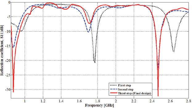
Figure 5 Reflection coefficient corresponding to design and simulation steps.
3 TUMOR DETECTION PERFORMANCES
In pathologic cases, breast tumors are generally produced in the glandular tissue. Electromagnetically, the tumor is characterized by particular dielectric properties, which are completely different from those of the healthy tissue. Dielectric properties of breast tumors used in this work are from the most agreed-upon and used empirical model [31]. Malignant tissues are characterized by different water and ionic content than other human body tissues, which leads to particular permittivity and conductivity and thus enables tumor detection.
3.1 Tumor detection and its size effect
It must be noted here that, while breasts are similar, very slight differences in size, shape, and internal structure are very common and normal for most women due to natural variations in tissue (fat/glandular) distribution, hormones, and genetics. The proposed approach is based on the reality that breast cancer is typically unilateral, meaning it starts in one breast, with bilateral (both breasts) cases occurring in only 1–3 % of patients [32, 33]. Thus, breast cancer detection with the proposed approach entails the examination of the two breasts of the patient and then comparing the shifting and magnitude of resonance frequencies covering the two operating frequency bands.
To evaluate the performances of the proposed IFA_SCL antenna sensor for tumor detection, the adopted scenario is given by Fig. 6 (a). The tumor to be detected is supposed to be of spherical shape with radii of 1, 2, and 5 mm and placed deeply in the glandular layer of the female breast phantom model (Brst_mdl.1) presented in section II, part A. Figure 6 (b) shows the obtained mesh of breast skin part corresponding to solved problem of this scenario. The entire model geometry is discretized into 469066 tetrahedrons, with the tumor divided into 649 finite elements having a minimum volume of 2.25794 10-5 mm3. The corresponding reflection coefficient is shown in Fig. 7. By comparison with the reflection coefficient corresponding to the final design obtained in section 2, part B, which is also represented in this figure, the tumor presence produces a resonance frequency shift and return loss modification in both lower and higher resonance frequencies covering the two operating frequency bands.
For the lower functional frequency band, the resonance frequency shifts from 0.875 GHz to higher frequencies of 0.879, 0.880, and 0.880 GHz for tumor radii of 1, 2, and 5 mm, respectively. Also, the simulated return loss (S11) changes from 30.94 dB to 31.38, 29.75 and 29.54 dB for these same tumor radii. For the higher operating frequency band, the resonance frequency shifts also occur to higher frequencies but it is less remarkable especially for the tumor radius of 1 mm. For this higher operating frequency band, the resonance frequency shifting and the corresponding amplitude are from (2.465 GHz, 32.29 dB) to values of (2.465, 33.94), (2.466, 34.91), and (2.467, 39.62) (GHz, dB) for tumor radii of 1, 2, and 5 mm, respectively.
From the obtained outcomes, a tumor presence with a radius of only 1 mm is detectable based on the resonance frequency shifting and the corresponding return loss magnitude changing. Effectively, the tumor presence is sensed in both operating frequency bands with some difference in sensing ability. Thus, the use of a multi-band antenna sensor allows for the efficient sensing of the tumor presence with remarkable resonance frequency shifting and/or return loss magnitude changing in at least one of their operating frequency bands. From the simulation performed in this section, tumor presence produces a shifting of value of at least 4 MHz for the resonance frequency that covers the ISM band of 915 MHz. This shifting value is very remarkable which means that this lower operating frequency is more sensitive to tumor presence in considered breast shape and size. Obtaining remarkable values allows practitioners to confirm easily the tumor presence. In addition, tumors of various sizes are also detectable. In fact, a tumor size increase leads to more resonance frequency shifting and/or more impedance matching in at least in one of the two operating frequency bands. Tumor presence produces variations in the impedance bandwidth corresponding to the two operating bands.
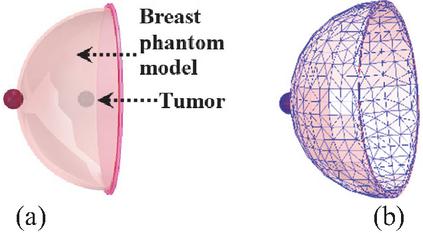
Figure 6 Tumor detection using designed IFA_SCL antenna: (a) tumor to be detected and (b) skin part meshing.
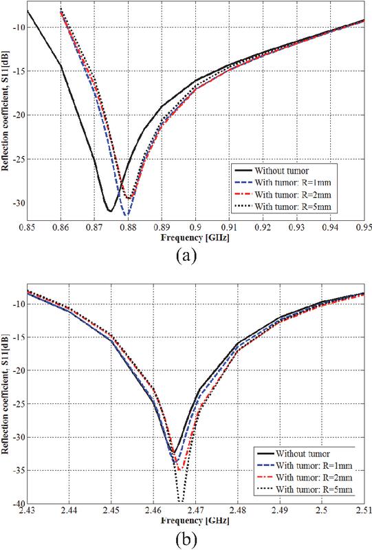
Figure 7 Effect of tumor presence on reflection coefficient: (a) ISM band of 915 MHz and (b) ISM band of 2.45 GHz.
3.2 Multiple tumors detection
In the breast, the tumor can appear in various regions of glandular tissue. The scenario of the parallel presence of six spherical shape tumors with same radius is examined using the breast model Brst_mdl.1 as shown in Fig. 8. To study the mentioned scenario, three stages are considered by varying the six tumors the same radius from 1, 2, to 5 mm in each stage. The corresponding simulated reflection coefficient is shown in Fig. 9. Effectively, multiple tumor presences are also detectable considering the resonance frequency shifting and the corresponding magnitude changing. For tumors with radius of 1 mm, the resonance frequency amplitude changes by 8.04 dB within the ISM band of 2.45 GHz without a shift in the resonance frequency, and for the ISM band of 915 MHz, a shifting of 4 MHz is simulated for the resonance frequency. A radius of 2 mm leads to resonance frequency shifting by around 4 MHz within the two ISM frequency bands. With the radius of 5 mm, the shifting is clearer within the frequency band of 2.45 GHz where a shifting of around 6 MHz is simulated. Thus, multiple tumors lead to more resonance frequency shifting for both resonance frequency, and the six tumors presence is sensed more in the ISM frequency band of 915 MHz.
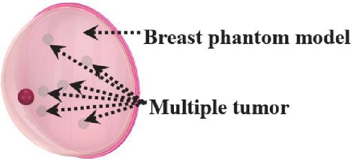
Figure 8 Multiple tumor detection scenario.
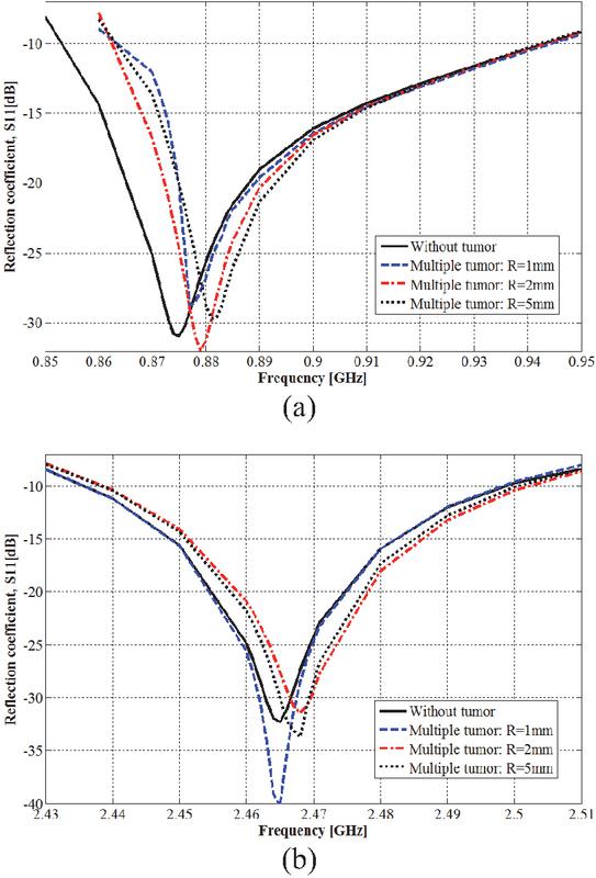
Figure 9 Multiple tumor effect on the IFA_SCL antenna performances: (a) ISM band of 915 MHz and (b) ISM band of 2.45 GHz.
3.3 Breast size effect
Breast size and shape may change naturally from one individual to another. These differences are influenced by genetics, related body weight, and age, and can also be affected by hormonal fluctuations, pregnancy, and weight changes. Because breasts are composed of fatty tissue, weight gain or loss directly impacts size. For these reasons, the antenna sensor must be usable with various sizes and shapes.
To simulate the detection ability of the proposed method considering the breast size variability, the spherical shape breast model Brst_mdl.1 used previously is added to two other spherical shape breast models: Brst_mdl.2 and Brst_mdl.3. The model Brst_mdl.2 has skin, fat, and glandular layers of radii of 51, 48.5, and 47 mm, respectively. The skin, fat, and glandular layers radii of the model Brst_mdl.3 are 47, 46, and 44.5 mm, respectively.
The simulated reflection coefficients corresponding to these three models are given in Fig. 10. Herein, the tumor is also suggested to be of spherical shape with a radius of 1 mm and placed deep within the glandular tissue.
Without a tumor and based on performed simulations, breast size and structure variations lead to different resonance frequencies for both the lower and upper operating frequency bands. While the spherical shape breast model of Brst_mdl.1 simulates resonance frequencies of 0.875 GHz and 2.465 GHz for lower and higher operating frequency bands, the model Brst_mdl.2 yields resonance frequencies of 0.881 GHz and 2.465 GHz, and the model Brst_mdl.3 produces resonance frequencies of 0.877 GHz and 2.464 GHz. Despite the distinguished resonance frequencies obtained with various breast spherical models, the two operating frequency bands of ISM 915 MHz and 2.45 GHz remain covered with high impedance matching. Thus, the 3D antenna sensor is usable with breasts of various sizes.
With a tumor and also based on performed simulations, the breast spherical model Brst_mdl.2 shifts the resonance frequencies from 0.881 to 0.882 GHz and from 2.465 to 2.466 GHz for the first and second operating frequency bands. The shifted resonance frequency corresponding to the higher frequency band is accompanied by amplitude changing of value of 3.32 dB and it is more than the amplitude changing (1.55 dB) corresponding to shifted resonance frequency within the lower frequency band. Thus, with this breast model of Brst_mdl.2, the ISM frequency band of 2.45 GHz is more sensitive to tumor presence. Also, for the breast spherical model Brst_mdl.3, the resonance frequencies shift from 0.877 to 0.879 GHz, and from 2.464 to 2.465 GHz for the first and the second operating frequency bands, respectively. The resonance frequency shifting observed with all three breast phantom models is accompanied by changes in the corresponding reflection coefficient magnitudes. From these various breast spherical models, the proposed approach and thus the proposed dual-band 3D antenna sensor have the potential to be used with breasts of various sizes.
From simulations affected in this section, the breast cancer detection ability of the proposed method is demonstrated by its capability to detect minor tumors even those with a radius only of 1 mm, either in single or multiple locations, and across various considered breast sizes. Tumor presence results in a significant frequency shift at least in one resonance frequency within two covered frequency bands of ISM 915 MHz and 2.45 GHz. The simulated value of resonance frequency shifting may reach 6 MHz, which is a very remarkable value. Furthermore, this shifting is accompanied by a change in the corresponding magnitudes with difference values until 7.33 dB.
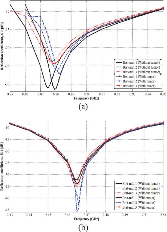
Figure 10 Breast size effect on tumor detection: (a) in the ISM 915 MHz frequency band and (b) in the ISM 2.45 GHz frequency band.
Since both the antenna’s electrical and radiation performances are significantly related to the surrounding material’s dielectric properties, the resonance frequencies and their magnitudes of the proposed 3D antenna are exploited to sense variations in dielectric properties of breast tissues due to the tumor presence. By placing the breast under examination between the radiation element and the ground plane, it becomes part of the effective substrate of the 3D antenna which leads to reach high sensing capability for variations in the breast’s dielectric properties.
To better show the detection ability of the proposed method, the next section designs and simulates this ability using breasts of teardrop and side-set shapes.
4 PRACTICAL TESTS AND TUMOR DETECTION USING MORE BREAST VARIABILITY SIMULATION
For both testing the clinical applicability and demonstrating the performance of the tumor detection with more breast shapes using the proposed method, two realistic human female breast models in side-set and teardrop shapes are simulated. A human tissues model, denoted Tbrst_mdl, is obtained by merging the side-set shape within a frontal torso phantom model, while the teardrop shape breast is included in the middle part of the computational and realistic female human body of VHP-Female version 2.1 and the resulting human tissues model is denoted Vbrst_mdl. The frontal torso is constituted of muscle, fat, and skin tissues. The entire version 2.1 of the VHP-Female realistic model contains 25 individual tissues distributed in 203 tissue parts. As in previous, the dielectric properties of various tissues are based on the Cole-Cole model.
A top and lateral view of the model Tbrst_mdl and the side-set shape breast tissues are depicted in Figs. 11 (a), (b) and (c). A top and lateral view of the model Vbrst_mdl, and the teardrop shape breast tissues are shown by Figs. 12 (a), (b) and (c).
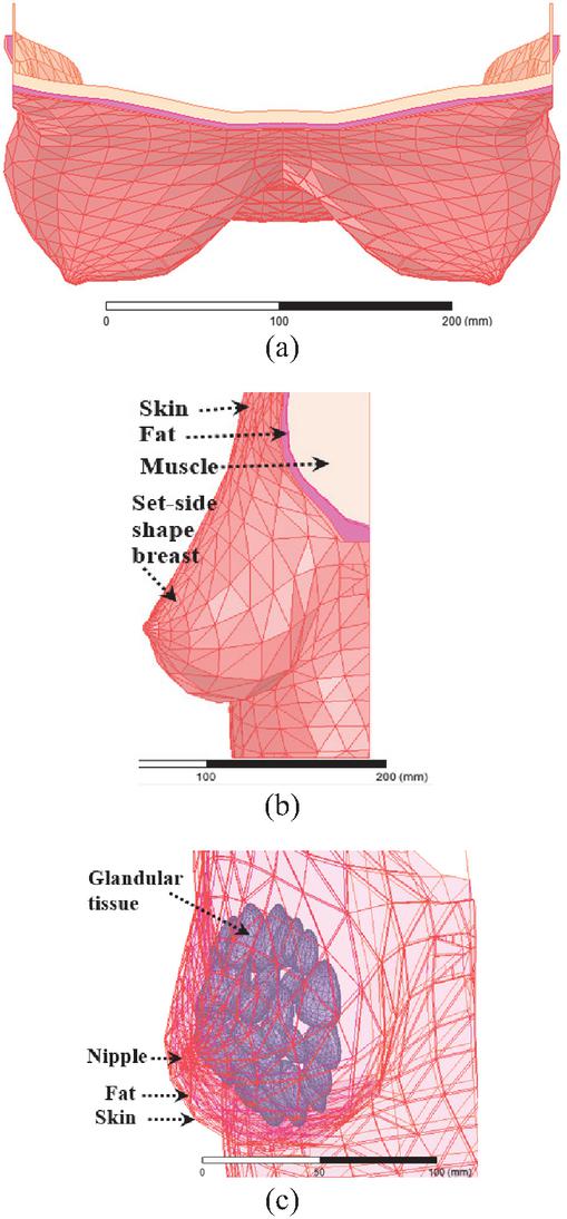
Figure 11 Tbrst_mdl model: (a) top view, (b) lateral view, and (c) side-set shape breast tissues.
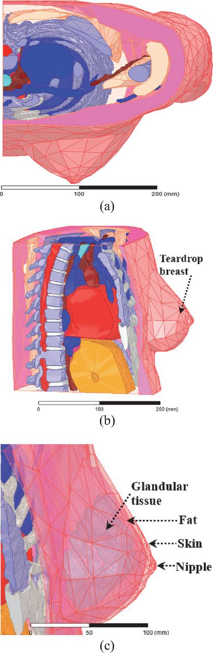
Figure 12 Vbrst_mdl model: (a) top view, (b) lateral view, and (c) teardrop shape breast tissues.
Figure 13 (a) presents the application of the 3D antenna sensor for tumor detection in practical testing for the Tbrst_mdl model, while Fig. 13 (b) shows this testing with the Vbrst_mdl model. The mesh corresponding to the geometry of the solved model depicted in Fig. 13 (b) is represented by Fig. 13 (c). Herein, the full mesh is constituted of 703454 tetrahedrons. The tumor is discretized into 766 tetrahedra finite elements with a minimum volume of 7.61211 10-6 mm3.
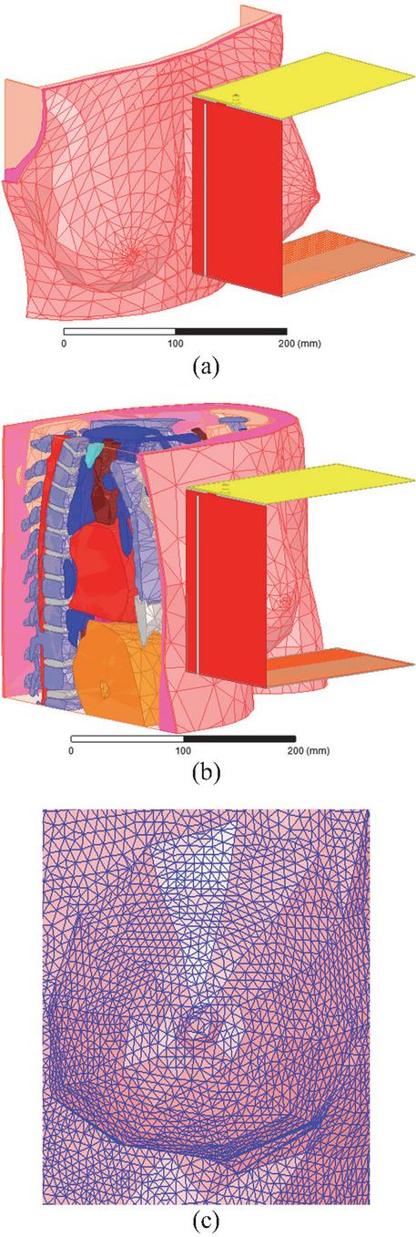
Figure 13 Clinical testing of the 3D antenna sensor with breast variability: (a) side-set shape breast examination, (b) teardrop shape examination, and (c) breast skin part meshing.
The tumor to be detected is positioned within the side-set shape breast of the Tbrst_mdl model as illustrated in Fig. 14 (a). For the teardrop shape breast of the model Vbrst_mdl examination, tumor presence is positioned in two different locations (upper and lower) as indicated in Figs. 14 (b) and (c). In all cases, the tumor is spherical, located within the glandular tissue, and has radii of 1, 2, or 5 mm.
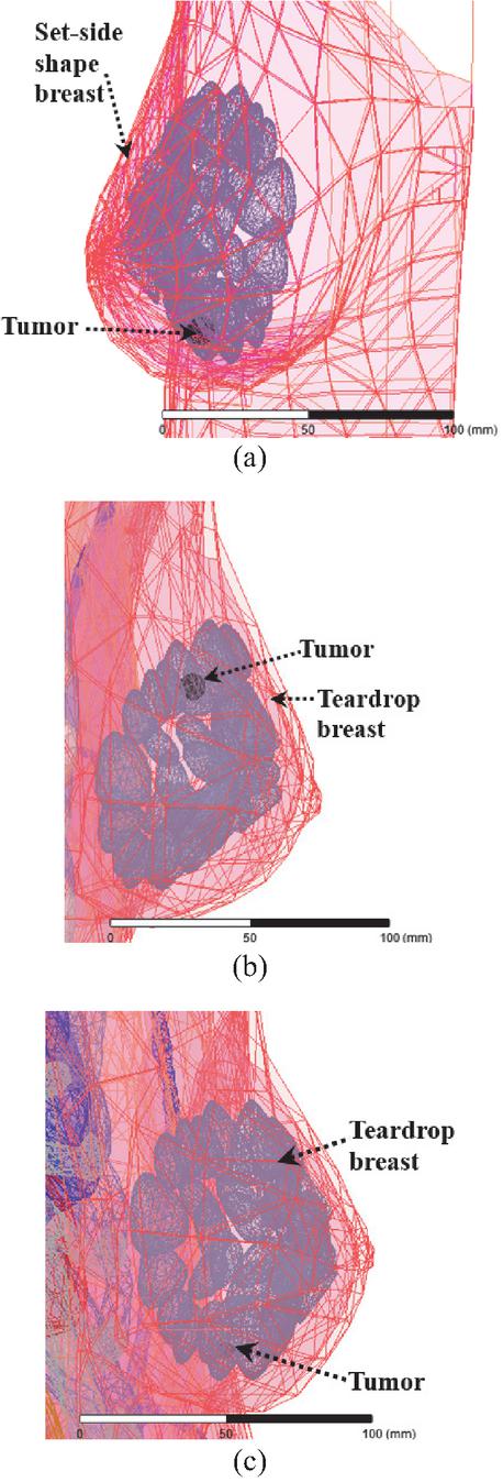
Figure 14 Tumor presence in glandular tissue: (a) tumor in side-set shape breast, (b) tumor in upper location in teardrop shape breast, and (c) tumor in lower location in teardrop shape breast.
As a function of tumor radius, simulated reflection coefficients obtained with the side-set and teardrop shape breast are shown in Figs. 15 (a, b), and Figs. 16 (a, b), with the tumor in the upper location for the latter.
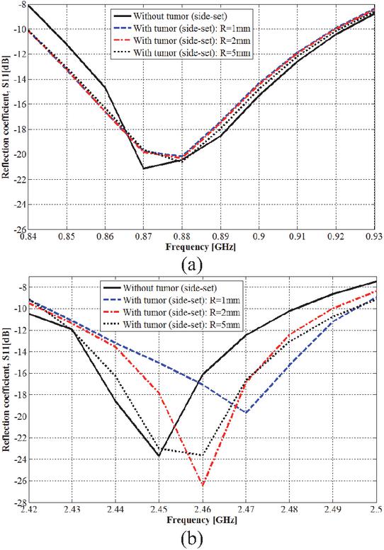
Figure 15 Tumor detection in side-set shape breast: (a) 915 MHz ISM band and (b) 2.45 GHz ISM band.
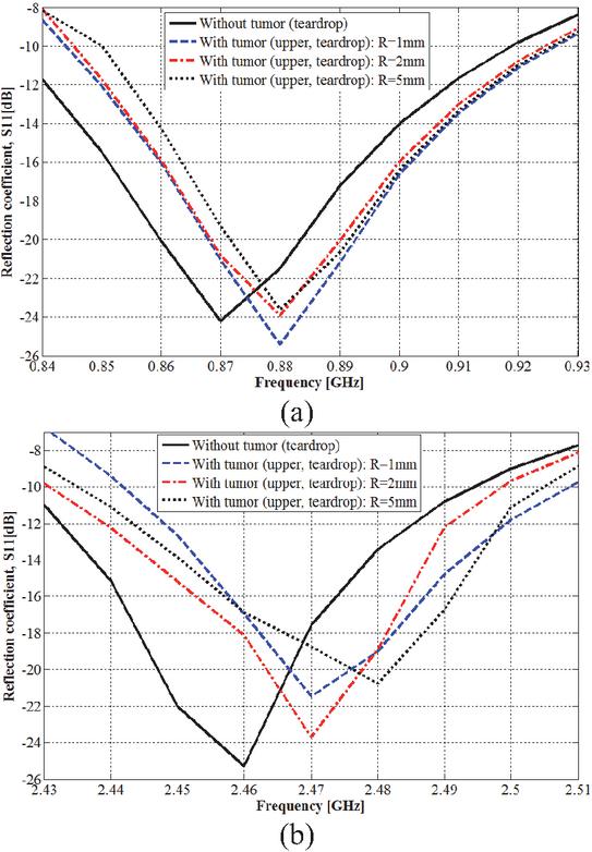
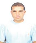
Figure 16 Tumor detection in teardrop shape breast: (a) 915 MHz ISM band and (b) 2.45 GHz ISM band.
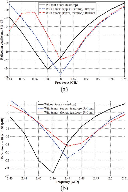
Figure 17 Tumor location effect on tumor detection: (a) 915 MHz ISM band and (b) 2.45 GHz ISM band.
Depending on the tumor location, simulated reflection coefficients obtained with the teardrop shape breast are shown in Figs. 17 (a) and (b), with the tumor radius fixed at 1 mm.
Herein, it must be noted that the required time for problem analysis and solving increases from the Tbrst_mdl to the Vbrst_mdl models due to the more model geometry complexity of this letter.
As precisely indicated in Fig. 15, the presence of a tumor within the breast model (Tbrst_mdl) results in a shift to higher frequencies (and changes in amplitude) for both lower and higher resonance frequencies of the 3D antenna sensor. The lower resonance frequency shifts (amplitude changes) from 0.870 GHz (21.15 dB) to 0.880 (20.17), 0.880 (20.29), and 0.880 GHz (20.62 dB) when the tumor radius is of 1, 2, and 5 mm, respectively. The higher resonance frequency shifts (amplitude changes) from 2.450 GHz (23.68 dB) to 2.470 (19.67), 2.460 (26.44), and 2.460 GHz (23.63 dB) also when the tumor radius is 1, 2, and 5 mm, respectively. Thus, the tumor presence is sensed significantly in both operating frequency bands with more remarkable shifting within the ISM frequency band of 2.45 GHz.
From Fig. 16, when the tumor is placed in the upper location within the teardrop shaped breast, both resonance frequencies shift to higher frequencies, which also yields a change in amplitude. The lower resonance frequency shifts (and amplitude changes) from 0.870 GHz (24.21 dB) to 0.880 (25.40), 0.880 (23.92) and 0.880 GHz (23.61 dB), and the higher resonance frequency shifts (and amplitude changes) from 2.460 GHz (25.29 dB) to 2.470 (21.45), 2.470 (23.69) and 2.480 MHz (20.47 dB). Tumor radius is of value at 1, 2, and 5 mm consecutively. Detection ability is more remarkable within the frequency band of 2.45 GHz, especially with tumor radius of 5 mm.
As shown in Fig. 17, the presence of a spherical tumor with a 1 mm radius in the lower location was detected by the 3D antenna sensor. A shift in the two resonance frequencies and a change in amplitude were obtained for various reached resonance frequencies. For the lower resonance frequency, the frequency shift (and the amplitude change) is from 0.870 GHz (24.21 dB) to 0.880 GHz (21.86 dB); the higher resonance frequency shifts (and amplitude changes) from 2.460 GHz (25.29 dB) to 2.470 GHz (18.43 dB).
For various simulations corresponding to this section, tumor presence introduces a significant shift of at least of 10 MHz in at least resonance frequency.
Based on reflection coefficients obtained by simulation with various breast spherical models (Brst_mdl.1, Brst_mdl.2, and Brst_mdl.3) used in sections II and III, as well as the side-set shape breast of the Tbrst_mdl model and the teardrop shape breast of the Vbrst_mdl model used in this section, it can be deduced that, despite the influence of the breast variability on the resonance frequencies and their amplitudes, the operating frequency bands remain covered and the 3D antenna sensor maintains its full-power for tumor detection. A tumor with radius of only 1 mm can be sensed and, in all cases, at least one resonance frequency shift by a remarkable value of few MHz is simulated.
The detection ability of the proposed method was confirmed in the two simulated practical tests, where remarkable frequency shifts were obtained. For both first and second tests, simulated frequency shifting is of minimum value of 10 MHz and a maximum value of 20 MHz were achieved for the two ISM frequency bands of 915 MHz and 2.45 GHz. Additionally, the shifted resonance frequency magnitude increases by up to 6.86 dB for the second test. Therefore, after examination of a woman’s breasts and by comparing the corresponding reflection coefficients, practitioners can deduce a tumor’s presence if there’s a remarkable difference in resonance frequency at least in one operating frequency band. The unhealthy breast is that which exhibits the higher resonance frequency (or frequencies).
5 PATIENT SAFETY CONFIRMATION
In any interaction between human body tissues and electromagnetic waves, the patient’s safety must be ensured. To reach this goal, the general public exposure is restricted by the two standards of IEEE C95.1-1999 (1-g Averaged SAR 1.6 W/Kg) [34] and IEEE C95.1-2005 (10-g Averaged SAR 2 W/Kg) [35]. For the proposed approach, the net-input power of the 3D antenna sensor should not exceed the corresponding value for each limit. Since the first limit is the most restricted, it will be used in this work.
Proposed experimental and clinical systems used in breast cancer detection using radar-based MWBI commonly operate at very low power levels where the power transmitted by antennas is within the 0.1 (10 dBm) to 10 mW (10 dBm) range. More exactly, many systems settle near 1 mW (0 dBm) as a practical balance point.
To verify patient safety during examination for early-stage breast cancer detection using the proposed antenna sensor, its net-input power is set to 1 mW. The simulated maximum 1-g averaged SAR values at resonance frequencies that cover the two interested frequency bands using the breast phantom model Brst_mdl.1 are given by Table 1.
Table 1 Simulated maximum 1-g averaged SAR in breast phantom model Brst_mdl.1 tissues
| Frequency [GHz] | Tissue | Max 1-g Avg. |
| SAR [mW/Kg] | ||
| 0.875 | Skin | 1.93 |
| Fat | 2.83 | |
| Glandular | 2.40 | |
| Muscle | 2.24 | |
| 2.465 | Skin | 3.79 |
| Fat | 3.68 | |
| Glandular | 2.00 | |
| Muscle | 3.15 |
From simulated maximum values of averaged SAR using the 1-g standard, patient safety remains ensured even as the antenna net-input power rises until 422.16 mW, which is much higher than the experimental transmitted power by radar-based MWBI antennas.
6 CONCLUSION
The present work discusses and presents a novel approach for early-stage breast cancer detection using only a single radiofrequency 3D antenna sensor. The simulated, designed, and used IFA-SCL antenna is of an innovative structure that allows placing the entire breast to be examined inside between its radiating element and ground plane, this enables efficient sensing of the dielectric properties of the breast under examination.
The proposed antenna is operational in two allocated frequency bands for medical applications, which are ISM 915 MHz and 2.45 GHz. Based on the shifting of resonance frequencies corresponding to these two bands and the related return loss magnitude changing, tumor presence and thus its detection is realized. A tumor with a radius of only 1 mm and placed deeply in the glandular tissue is detectable with various sizes of a spherical shape breast model; a shifting of 4 MHz in the resonance frequency that covers the ISM 915 MHz is obtained. Testing by simulation of the proposed approach with realistic and variable breasts yields very satisfactory results for practical use. From these tests, a significant and a remarkable resonance frequency shifting of 20 MHz is simulated within the frequency band of ISM 2.45 GHz. From simulated results, the 3D antenna sensor is able to sense tumor presence with variable breast shapes and sizes.
With the proposed approach, tumor detection is easy, fast, less painful, safe and comfortable, and with low-cost. In addition, false-positive (a suspicious area that appears to be cancerous, but no cancer is present) and false-negative (incorrectly suggesting no cancer is present, when a tumor is actually present) results are fully detected by the proposed 3D antenna sensor, which may allow this novel approach to become a promising and alternative way for early-stage breast cancer detection.
References
[1] H. M. E. Misilmani, T. Naous, S. K. A. Khatib, and K. Y. Kabalan, “A survey on antenna designs for breast cancer detection using microwave imaging,” IEEE Access, vol. 8, pp. 102570–102594, 2020.
[2] N. Rezaei, Breast Cancer Treatment: An Interdisciplinary Approach. Switzerland: Springer Nature, 2024.
[3] Y. Bakar and A. Tugral, Managing Side Effects of Breast Cancer Treatment. Switzerland: Springer Nature, 2024.
[4] K. V. Ramani, H. Ramani, S. S. Alurkar, B. S. Ajaikumar, and R. G. Trivedi, Breast Cancer: Medical Treatment, Side Effects and Complementary Therapies. New York: Momentum Press, 2017.
[5] U. Veronesi, A. Goldhirsch, P. Veronesi, O. D. Gentilini, and M. C. Leonardi, Breast Cancer: Innovations in Research and Management. Switzerland: Springer International Publishing, 2017.
[6] O. Al Jarroudi, K. El Bairi, and G. Curigliano, Breast Cancer Research and Treatment. Switzerland: Springer Nature, 2023.
[7] K. H. R. Tkaczuk, S. B. Kesmodel, and S. J. Feigenberg, Handbook of Breast Cancer and Related Breast Disease. New York: Demos Medical Publishing, 2017.
[8] G. Gasparini and D. F. Hayes, Biomarkers in Breast Cancer: Molecular Diagnostics for Predicting and Monitoring Therapeutic Effect. New Jersey: Humana Press, 2006.
[9] E. Bombardieri, G. Bonadonna, and L. Gianni, Breast Cancer: Nuclear Medicine in Diagnosis and Therapeutic Options. Berlin Heidelberg: Springer-Verlag, 2008.
[10] S. Mallick and C. K. Sharma, Evidence in Breast Cancer. Singapore: Springer Nature, 2024.
[11] S. J. Nass, I. C. Henderson, and J. C. Lashof, Mammography and Beyond: Developing Technologies for the Early Detection of Breast Cancer. Washington DC: National Academic Press, 2001.
[12] M. Z. Mahmud, M. T. Islam, N. Misran, S. Kibria, and M. Samsuzzaman, “Microwave imaging for breast tumor detection using uniplanar AMC based CPW-fed microstrip antenna,” IEEE Access, vol. 6, pp. 44763–44775, 2018.
[13] D. N. Elsheakh, O. M. Fahmy, M. Farouk, K. Ezzat, and A. R. Eldamak, “An early breast cancer detection by using wearable flexible sensors and artificial intelligent,” IEEE Access, vol. 12, pp. 48511–48529, 2024.
[14] N. Nithya and M. S. K. Manikandan, “Enhancement of multifrequency microwave tomography breast imaging system using flexible preconditioner based Krylov subspace methods,” Applied Computational Electromagnetics Society (ACES) Journal, vol. 37, no. 6, pp. 664–671, June 2022.
[15] A. K. Alqallaf, R. K. Dib, and S. F. Mahmoud, “Microwave imaging using synthetic radar scheme processing for the detection of breast tumors,” Applied Computational Electromagnetics Society (ACES) Journal, vol. 31, no. 2, pp. 98–105, Feb. 2016.
[16] B. Guetaf, A. Chaabane, A. Khalfallaoui, and H. Attia, “Narrow-band circularly polarized antenna for medical microwave imaging and health monitoring applications,” Applied Computational Electromagnetics Society (ACES) Journal, vol. 38, no. 6, pp. 424–438, June 2023.
[17] I. Unal, B. Türetken, and C. Canbay, “Spherical conformal bow-tie antenna for ultra-wide band microwave imaging of breast cancer tumor,” Applied Computational Electromagnetics Society (ACES) Journal, vol. 29, no. 2, pp. 124–133, Feb. 2014.
[18] R. A. Petrella, K. H. Schoenbach, and S. Xiao, “A dielectric rod antenna for picosecond pulse stimulation of neurological tissue,” IEEE Transactions on Plasma Science, vol. 44, no. 4, pp. 708–714, Apr. 2016.
[19] M. R. S. Ramu and K. Arunachalam, “Miniaturized 434 MHz cavity encapsulated patch antenna for superficial hyperthermia treatment,” IEEE Journal of Electromagnetics, RF and Microwaves in Medicine and Biology, vol. 7, no. 4, pp. 392–399, Dec. 2023.
[20] M. Behih, F. Bouttout, T. Fortaki, and C. Dumond, “A novel wideband and multiband implantable antenna design for biomedical telemetry,” Applied Computational Electromagnetics Society (ACES) Journal, vol. 37, no. 04, pp. 441–457, Apr. 2022.
[21] M. Behih, F. Bouttout, T. Fortaki, and C. Dumond, “A novel multifunction implantable antenna design for biomedical telemetry,” in 2021 International Applied Computational Electromagnetics Society Symposium (ACES), Hamilton, ON, Canada, pp. 1–4, 2021.
[22] N. Hammouch, A. Rghioui, and H. Ammor, “A low-cost UWB microwave imaging system for early-stage breast cancer detection,” Multimed. Tools Appl., July 2024.
[23] M. A. Aldhaeebi, T. Almoneef, S. Bamatraf, A. O. Aldhaibain, O. Bakhalah, S. Alhdad, S. Bakhalah, and M. K. Saleem, “Near-field metasurface sensor for an early-stage breast cancer detection,” Sensors International Journal, vol. 6, 2025.
[24] S. Reelekshmi and S. P. Sankar, “Design and analysis of novel miniaturised triple band antenna for breast cancer detection,” Microsyst. Technol. Journal, vol. 28, pp. 1715–1726, 2022.
[25] I. Jahan and M. A. Kabir, “Microstrip patch antenna for breast cancer detection,” in 5th International Conference on Electrical Information and Communication Technology (EICT), Khulna, Bangladesh, Dec. 2021.
[26] T. Lanka, D. Chaturvedi, M. V. L. Bhavani, and A. Kumar, “Design of PRS enabled monopole slotted-antenna sensor for breast tumor detection,” Scientific Reports, vol. 15, 2025.
[27] K. Youssef, M. A. Zahhad, H. Kanaya, and A. H. El-Malek, “A unified approach for breast cancer discrimination using metasurface-based microwave technology,” Discover Applied Sciences, vol. 6, July 2024.
[28] S. N. Makarov, G. M. Noetscher, J. Yana-Madala, M. W. Piazza, S. Louie, A. Proko, A. Nazarian, and A. Nummenmaa, “Virtual human models for electromagnetic studies and their applications,” IEEE Reviews in Biomedical Engineering, vol. 10, pp. 95–121, Dec. 2017.
[29] V. R. Nawati, B. K. Sujatha, and G. S. Karthikeya, “A compact dual-polarized probe-fed UWB antenna system for breast cancer detection applications,” Wireless Netw., vol. 30, pp. 3039–3050, 2024.
[30] S. Gabriel, R. W. Lau, and C. Gabriel, “The dielectric properties of biological tissues,” Phys. Med. Biol., vol. 41, pp. 2231–2293, 1996.
[31] M. Lazebnik, L. McCartney, D. Popovic, C. B. Watkins, M. J. Lindstrom, J. Harter, S. Sewall, A. Magliocco, J. H. Booske, M. Okoniewski, and S. C. Hagne, “A large-scale study of the ultrawide band microwave dielectric properties of normal breast tissue obtained from reduction surgeries,” Phys. Med. Biol., vol. 52, no. 10, pp. 2637–2656, 2007.
[32] M. Nameur, “Unilateral versus bilateral breast cancers, synchronous versus non-synchronous bilateral breast cancers: Results of a long survey (25 years) concerning 3632 patients,” Journal of Clinical Oncology, vol. 22, pp. 729–729, 2004.
[33] J. Oh and B. Park, “Bilateral breast cancer,” Journal of Clinical Oncology, vol. 25, pp. 17073–17073, June 2007.
[34] Safety Levels with Respect to Human Exposure to Radiofrequency Electromagnetic Fields, 3 kHz to 300 GHz, IEEE Standard C95.1, 1999.
[35] Safety Levels with Respect to Human Exposure to Radiofrequency Electromagnetic Fields, 3 kHz to 300 GHz, IEEE Standard C95.1, 2005.
Biographies
Mohamed Behih was born in Bordj Bou Arreridj, Algeria, in 1981. He received the Engineer degree in electronic engineering and Magister degree in communication from Setif University, in 2004 and 2007, respectively, and the Ph.D. degree in communication engineering from the University of Batna 2, in 2024. Presently, he is a doctor at the Institute of Electronics and Telecommunications, University of Bordj Bou Arreridj. His fields of research include telecommunications systems and networks, biomedical engineering, interaction between electromagnetic wave and human body, and medical devices and antennas.

Christophe Dumond was born in Tulle, France, on 22 October 1966. He received the Ph.D. in Optic Communications and Microwaves from University of Limoges in 1994. His works concern the electromagnetic answer of wire structures to fast transient perturbations. In 2007, he joined the Institut Pluridisciplinaire de Recherche en Ingénierie des Systèmes Mécaniques et Energétique (PRISME) of University of Orléans. His fields of research include fractal antennas, high Tc superconducting microstrip patch, phased arrays and implantable antennas for bio-telemetry. He is also a teacher and head of the electrical engineering department at the Institut Universitaire de Technologie (IUT) of Chartres.

Farid Bouttout received the B.Sc. and M.Sc. degrees in electronic engineering from the University of Constantine, Constantine, Algeria, in 1994 and 1997, respectively, and the Ph.D. degree in electronic engineering from the University of Setif in 2001. He was granted a three-year postdoc study on design of planar antennas for medical applications at the Commissariat à l’Energie Atomique (CEA) and at the University of Paris VI, France. He is currently a professor with the Institute of Electronics and Telecommunications, University of Bordj Bou Arreridj. His current research interests include planar and cylindrical microstrip antennas and transmission lines, computational electromagnetics, high performance computing, neural networks, and fuzzy logic.

Tarek Fortaki was born in Constantine, Algeria, in 1972. He received the State Engineer, M.Sc., and Ph.D. degrees in electronics and communications engineering from the University of Constantine, Constantine, Algeria, in 1995, 1999, and 2004, respectively. He joined the Department of Electronics at University of Batna in 2000; he was promoted to full professor in 2010. He has supervised 21 Ph.D. theses (including 19 defended). He has authored or co-authored more than 150 research publications in peer-reviewed journals and conference proceedings. He has served as a TPC/IPC member for different international conferences, alongside a reviewer for several prestigious scientific journals. He has been invited to deliver numerous keynote or plenary talks in international conferences. He is widely recognized for his contributions to the numerical modelling of patch antennas embedded in multilayered anisotropic media. His current research interests include microwave electronics, numerical and analytical techniques for electromagnetic modelling, antennas, HF propagation, complex media, artificial materials, computational intelligence, and intelligent design of microwave devices.
ACES JOURNAL, Vol. 41, No. 01, 48–63
DOI: 10.13052/2026.ACES.J.410106
© 2026 River Publishers