A Miniaturized Dual-Band Circularly Polarized Antenna With Broadband and Flexible Frequency Ratio
Yunlong Mao1, Deshun Li1, Yifan Shen1, Atef Z. Elsherbeni2, and Si Li1
1Ocean College
Jiangsu University of Science and Technology, Jiangsu 212003, China
maoyunlong0511@just.edu.cn, just_lds@163.com, shenyifan@stu.just.edu.cn, lisi0511@just.edu.cn
2Electrical Engineering Department
Colorado School of Mines, Golden 80401, USA
aelsherb@mines.edu
Submitted On: August 12, 2025; Accepted On: November 03, 2025
ABSTRACT
A dual-band circularly polarized antenna with AR (Axial Ratio) bandwidth enhanced using parasitic strips and triangle notches is proposed in this paper. The proposed antenna comes with a size of mm ( at 2.45 GHz), which is composed of two layers of substrate and three layers of metallic patterns. With the introduction of parasitic strips on the top metallic layer and etched triangles on the ground plane, this antenna exhibits dual-band circularly polarized character. A flexible frequency ratio from 1.57 to 2.01 could be obtained by changing the size of the triangle notches. Simulations and measurements verified that the proposed antenna shows relative S11-10 dB bandwidth of 36.6% (2.23–3.25 GHz) and 51.3% (3.58–6.05 GHz), relative AR3 dB bandwidth of 17.6% (2.32–2.77 GHz) and 11.1% (4.65–5.30 GHz), peak gains of 4.45 dBic and 6.24 dBic, respectively. This antenna is a good candidate for the 2.45 GHz communication band and the 5G sub-6 NR band applications.
Keywords: Circular polarization, dual-band, microstrip antenna, parasitic patch, ultra-wideband.
I. INTRODUCTION
The rapid development of 5G networks has brought many opportunities, driving the advent of new applications in areas such as the Internet of Things (IoT) [1]. Given the proliferation of diverse communication standards, contemporary wireless devices require multiband antenna operation to ensure functional compatibility. Consequently, antennas must support multiple frequency bands while maintaining a low-profile, planar form factor to facilitate seamless integration into compact and geometrically constrained platforms.
There are various approaches proposed in the realm of dual-band circularly polarized antenna design. One such approach integrates two radiating structures on a substrate, each with distinct operating frequencies. This configuration can be utilized for array antenna [2, 3, 4], stack of patches [5, 6, 7, 8], or a combination of electric and magnetic dipoles [9, 10]. The second approach uses the integration of dual-band antennas with polarization-converting surfaces, such as the polarization rotation AMC (Artificial Magnetic Conductor) [11] and the dual-linear-to-circular polarization converters [12]. These designs in general necessitate the use of additional substrates to facilitate specific polarization transitions or rotating structures, which also result in high-profile and structural complexity. To deal with these limitations, researchers are focusing on the study of the incorporation of slots into the radiating patch [13, 14]. This method renders the antenna structure uncomplicated, while maintaining the antenna’s dimensions, and enables the antenna’s operational frequency band to be flexibly adjustable. However, a common issue is that the circularly polarized bandwidth is relatively narrow. A thorough analysis of circular polarization reveals that the primary factor contributing to the constricted circularly polarized bandwidth is the substantial Q value [14, 15] introduced by the narrow slots. Several approaches were employed to obtain reduced Q value, such as widening the width of slots [14, 16, 17] and employing parasitic patches [15, 16, 18, 19]. However, from the aspect of equivalent circuits, either of these methods could widen the AR (Axial Ratio) bandwidth at one frequency but may not be applicable for two or more bands. Therefore, it is still a challenge to obtain wide AR bandwidth at multiple bands.
In this paper, we propose a low-profile miniaturized dual-band circularly polarized antenna with wideband AR in both operational bands. At the lower frequency band, the AR bandwidth is widened using parasitic strips, while at the higher frequency band, the AR bandwidth is widened by triangle notches etched on the ground plane. As a consequence, both AR bands are individually adjustable. Moreover, the proposed antenna achieved FFR (Flexible Frequency Ratio) from 1.57 to 2.01 by changing the size of the notched triangles. Simulations and measurements were operated, and comparisons to some recent researchers identified the advancement of the proposed antenna.
II. ANTENNA DESIGN AND PARAMETRIC STUDIES
A. Antenna element configuration
The geometry of the designed dual-band circularly polarized antenna is shown in Fig. 1. It is composed of two layers of substrates with plane size of 5353 mm2. The first substrate height is 3 mm and its relative permittivity is . The radiation patch is printed on the top side of the substrate, and the ground plane is on the other side. The second substrate height is 0.813 mm with . An L-shaped feedline is printed on its bottom side. Detailed geometrical parameters are listed in Table 1.
Table 1: Parameters of the proposed antenna (unit: mm)
| D | L | W | l1 | l2 | l3 | l4 |
| 53 | 10 | 2 | 14 | 7 | 8 | 28 |
| l5 | w1 | w2 | w3 | w4 | w5 | lb |
| 15 | 4.5 | 5.5 | 1.5 | 6 | 7.5 | 32 |
| ls | h1 | h2 | g1 | g2 | a | b |
| 28 | 3 | 0.813 | 0.3 | 0.4 | 12 | 4 |
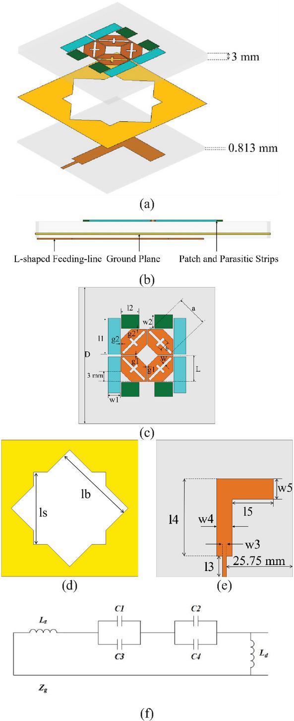
Figure 1: Antenna structure. (a) 3D view, (b) side view, (c) top view, (d) ground plane, (e) bottom view, (f) equivalent circuit.
B. Design procedure
To generate circularly polarized waves, it is essential to produce two orthogonal currents with 90 degrees phase difference. Therefore, we first designed an octagonal patch as displayed in Fig. 2 (a), and the ground plane is as displayed in Fig. 2 (d). This patch is fed by an L-shaped microstrip. Such a structure exhibits the potential of generating circularly polarized waves, but the bandwidth is limited.
The frequency resonance condition can be expressed as [20]
| (1) |
Therefore, resonance frequency modulation can be achieved by introducing additional capacitive or inductive components into the circuit system. The inductance value is predominantly governed by the thickness of the substrate in planar circuit implementations. Concurrently, the equivalent capacitance exhibits dual dependency on both the geometric configuration of patch elements and the inter-element gap . Therefore, in this paper, the addition of parasitic strips near the center patches results in the formation of a capacitance at the gap between the center patch and the parasitic strips, due to the accumulation of moving electrons. Consequently, edge capacitors , and were introduced at the gap to facilitate the desired electrical effects. Additionally, the center patches and ground plane inherently exhibit inductive characteristics. Therefore, the resonant frequency can be expressed as [21, 22, 23, 24, 25]
| (2) |
in equation (B.), C, , and can be approximated as follows:
| (3) | |
| (4) | |
| (5) | |
| (6) |
Thus, it can be observed that, with the center patches dimensions and gap being fixed, the dimensions of the parasitic strips constitute the critical factor affecting the total capacitance. Therefore, adjusting the dimensions of two distinct parasitic strip sets enables modulation of the total capacitance , thereby influencing the antenna’s resonant frequency.
In this study, we compared the case with and without parasitic strips, Ant. 1 and Ant. 2. It is shown that the introduction of parasitic strips improved the impedance matching at higher frequencies while successfully achieving a wideband circular polarization at frequencies around 2.5 GHz. The introduction of parasitic strips modifies the current distribution, resulting in y-direction and x-direction currents exhibiting equal amplitude with a 90∘ phase difference in the low-frequency band, thus achieving circular polarization at lower frequencies. However, the circular polarization at around 4.6 GHz is almost vanished.
To introduce circular polarization bandwidth in the high-frequency band, observation of surface current vectors on the ground plane at 5 GHz revealed a current mismatch condition at the etched edges. Consequently, a set of triangular notches were etched around the original square slot, with the final configuration shown in Fig. 1 (d). Comparing Ant. 2 and the proposed one, it is observed that the introduction of the triangle notches enhanced circularly polarization at higher frequencies while maintaining a similar operating band as Ant. 2. Circular polarization is also observed from 4.45.22 GHz. Such an effect is a result of the strategy that extended the current path as illustrated in Fig. 3, making it close to the half wavelength at 5 GHz.
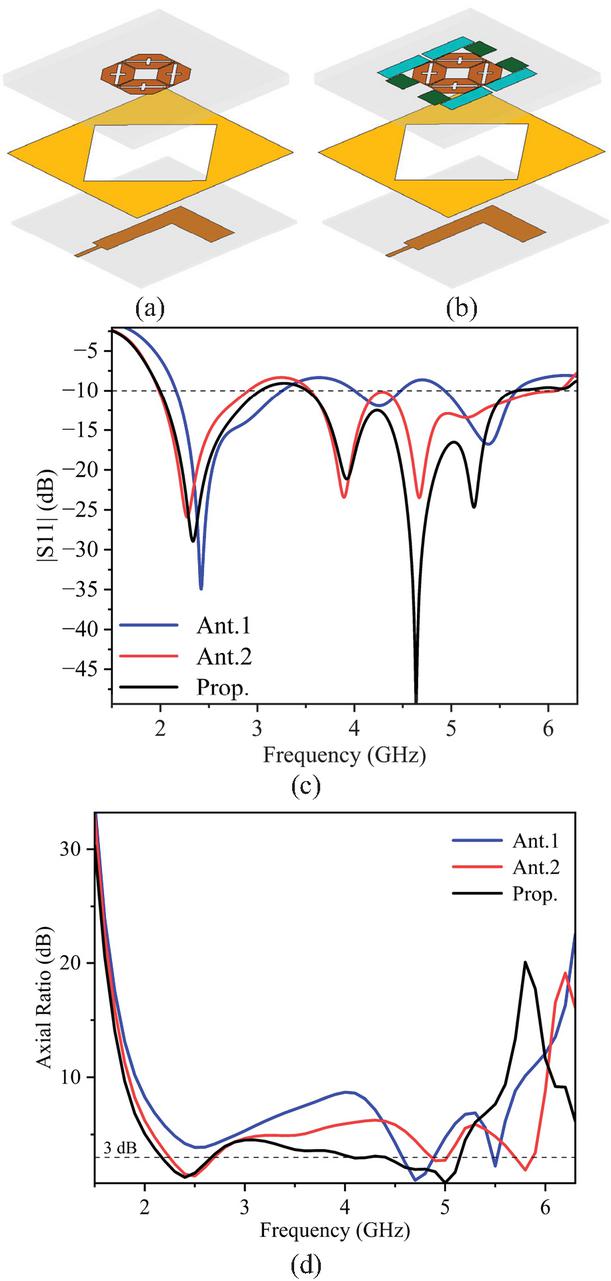
Figure 2: (a) Structure of Ant. 1, (b) structure of Ant. 2, (c) simulated S parameters S11, (d) simulated axial ratio AR of Ant. 1, Ant. 2, and proposed antenna.
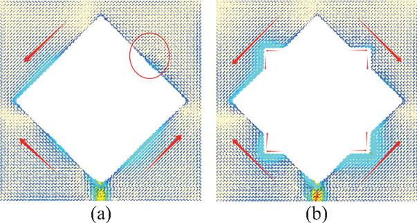
Figure 3: Current path at 5 GHz. (a) Ant. 2 and (b) proposed antenna.
C. Parametric analysis
To further validate the effects of parasitic strip integration and slot etching on antenna performance, we analyzed their parameters separately using CST Studio Suite. The impacts of parasitic strips and etched notches on antenna S11 and AR are demonstrated in Figs. 4 and 5. As observed in Fig. 4, the two distinct parasitic strip sets with differentiated dimensions induce frequency band-specific modifications, enabling independent regulation of impedance matching across distinct frequency bands.
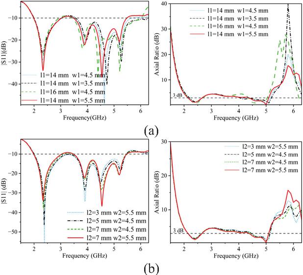
Figure 4: S11 and AR versus frequency for (a) l1 and w1 and (b) l2 and w2.
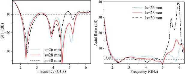
Figure 5: S11 and AR versus frequency for different values of ls.
As shown in Fig. 5, significant modifications in S11 and AR are observed. With the increase of ls, the operational bandwidth at lower frequencies exhibits minor expansion, while the upper cutoff frequency at higher frequencies demonstrates a pronounced downward shift. Figure 5 (b) reveals that the first AR frequency range remains nearly unchanged, whereas the second AR frequency range shifts substantially from 4.65–5.20 GHz to 3.34–4.37 GHz, with its corresponding minimum AR value shifting from 5 GHz to 4.13 GHz. This phenomenon occurs because ls directly governs the resonant frequency. As ls increases, the frequency ratio decreases from 2.01 to 1.57, elongating the current propagation path and thereby exciting resonance at lower frequencies.
The effects that the parasitic strips and the notches have on S11 and AR are plotted in Figs. 4 and 5. In Fig. 4, the increase of the parasitic strips size barely affects S11 and AR at lower frequencies but would cause a little shift at higher frequency. That is because the impedance at the operating frequencies is changing smoothly, hence slight changes of the parasitic strips would cause little difference on the antenna input impedance.
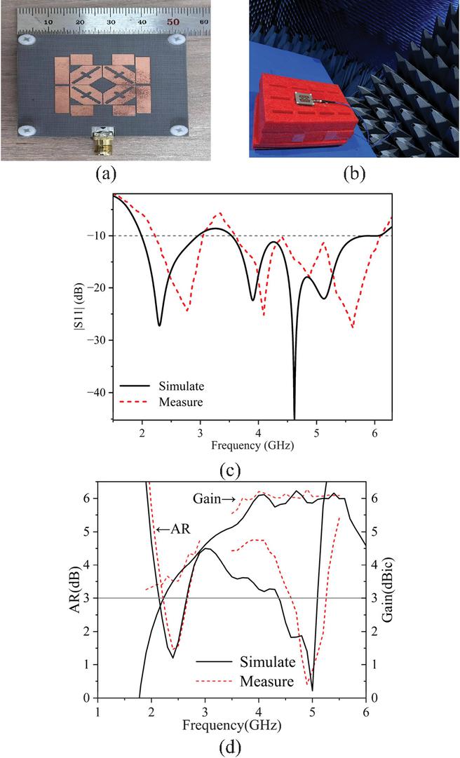
Figure 6: (a), (b) Photo of antenna prototype. Simulation and measurement results of (c) S11 and (d) AR and gain.
In Fig. 5, significant changes are observed for both S11 and AR. In Fig. 5, with the increase of ls, the working frequency band at lower frequencies is only slightly extended, while at higher frequencies, the upper cut-off frequency is greatly shifted to a lower frequency. As reflected in Fig. 5 (b), the first AR frequency range is barely changed, while the second AR frequency range exhibits significant shift, from 4.655.20 GHz to 3.344.37 GHz, of which the corresponding minimum AR value shifted from 5 GHz to 4.13 GHz. As a consequence, the frequency ratio is changed from 2.01 to 1.57. That is because ls affects the resonant frequency. With the increasement of ls, the current flow path would be extended, hence excited resonances at lower frequencies.
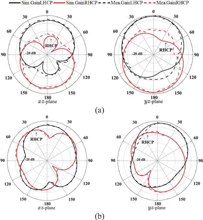
Figure 7: Simulated and measured normalized radiation patterns of the proposed antenna at (a) 2.45 GHz on xz-plane and yz-plane and (b) 5.0 GHz on xz-plane and yz-plane.
Table 2: Comparison with other dual-band circularly polarized antennas
| Ref. | (GHz) | FB/FB | ARB/ARB | Gai/Gai (dBic) | Antenna Size ( at ) |
| [13] | 2.35/4.15 | 18.2%/17.8% | 72.1%/63.5% | 7.87/5.71 | 0.94*0.82*0.22 |
| [14] | 2.49/3.44 | 35.48%/25% | 7.1%/5.06% | 3.36/3.16 | 1.47*1.47*0.01 |
| [26] | 3.48/5.03 | 30.48%/18.51% | 8.06%/6.38% | 6.9/7.3 | 1.33*1.33*0.34 |
| [27] | 2.91/5.41 | 18.56%/10.45% | 37.03%/33.9% | 4.79/4.27 | 1.79*1.79*0.02 |
| [28] | 5.77/9.3 | 4.5%/2.7% | 23.07%/28% | 8.4/6.35 | 1.28*1.28*0.07 |
| This Work | 2.74/4.64 | 36.6%/51.3% | 53.19%/21.56% | 4.45/6.24 | 0.64*0.64*0.04 |
| : actual wavelength of the center frequency of the low-frequency range,ARBW: relative bandwidth of circular polarization within the passband [13]. | |||||
III. ANTENNA MEASUREMENT
The proposed antenna was fabricated as shown in Fig. 6 (a) and measured using Keysight N5227A network analyzer and Satimo system. Figures 6 (b)–(c) shows that the measured and simulated results are well matched. Due to fabrication and measuring errors, a slight frequency shift was observed, but still within the required frequency range. The proposed antenna achieves a measured S11-10 dB bandwidth of 36.6% (2.23–3.25 GHz) and 51.3% (3.58–6.05 GHz), AR3 dB bandwidth of 17.6% (2.32–2.77 GHz) and 11.1% (4.65–5.20 GHz), and peak gains of 4.45 dBic and 6.24 dBic, respectively. Figures 7 (a)–(b) show the simulated and measured normalized radiation patterns in the xz- and yz-planes of the two frequency bands·
Comparisons between the proposed antenna and recent reported ones are listed in Table 2. As observed, the proposed antenna has achieved widest relative bandwidth for both impedance frequency bands and AR bandwidth, while obtaining high gain and small size. Therefore, it is a better candidate for wireless applications.
IV. CONCLUSION
This paper proposes a low-profile dual-band circularly polarized antenna for use in the 2.45 GHz communication band and the 5G sub-6 NR band (3.5–5.7 GHz). The proposed antenna employs a stacked and microstrip line-fed structure to produce ultra-wide operating bandwidths as well as circularly polarized radiation responses in the low- and high-frequency bands, respectively. The introduction of a star-slot structure at the ground plane not only affects the coupling efficiency but also affects the operating bandwidth and circularly polarized bandwidth. Test results show that the antenna has wide operating bandwidth and circularly polarized bandwidth. Comparing with existing methods, the antenna does not require the use of two antenna radiators or additional polarization conversion or rotating substrate, which provides a new approach for the design of dual-band antennas. These features make the proposed antenna attractive in duplex communication systems.
REFERENCES
[1] G. A. Akpakwu, B. J. Silva, G. P. Hancke, and A. M. Abu-Mahfouz, “A survey on 5G networks for the Internet of Things: Communication technologies and challenges,” IEEE Access, vol. 6, pp. 3619–3647, 2017.
[2] C. D. Bui, N. Nguyen-Trong, and T. K. Nguyen, “A planar dual-band and dual-sense circularly polarized microstrip patch leaky-wave antenna,” IEEE Antennas and Wireless Propagation Letters, vol. 19, no. 12, pp. 2162–2166, Dec. 2020.
[3] N. Nguyen-Trong, S. J. Chen, and C. Fumeaux, “High-gain dual-band dual-sense circularly polarized spiral series-fed patch antenna,” IEEE Open Journal of Antennas and Propagation, vol. 3, pp. 343–352, 2022.
[4] J.-N. Wang, Z.-J. Guo, and Z.-C. Hao, “A millimeter-wave planar dual-band array antenna having individually LHCP and RHCP radiation characteristics,” IEEE Open Journal of Antennas and Propagation, vol. 3, pp. 768–773, 2022.
[5] N. Yan, K. Ma, H. Zhang, and P. Jia, “An SISL triple-band multimode stacked-patch antenna with L-strips for multiband applications,” IEEE Transactions on Antennas and Propagation, vol. 67, no. 2, pp. 1284–1288, Feb. 2019.
[6] Y. Liu, Z. Yue, Y. Jia, Y. Xu, and Q. Xue, “Dual-band dual-circularly polarized antenna array with printed ridge gap waveguide,” IEEE Transactions on Antennas and Propagation, vol. 69, no. 8, pp. 5118–5123, Aug. 2021.
[7] N. Claus, “High-performance air-filled multiband antenna for seamless integration into smart surfaces,” IEEE Antennas and Wireless Propagation Letters, vol. 20, pp. 2260–2264, 2021.
[8] K. Xue, “A dual-polarized filtering base-station antenna with compact size for 5G applications,” IEEE Antennas and Wireless Propagation Letters, vol. 19, pp. 1316–1320, 2020.
[9] C. D. Bui, N. Nguyen-Trong, and T. K. Nguyen, “A planar dual-band and dual-sense circularly polarized microstrip patch leaky-wave antenna,” IEEE Antennas and Wireless Propagation Letters, vol. 19, no. 12, pp. 2162–2166, Dec.2020.
[10] P. Liu, F. Jia, Y. Zhang, G. Su, Q. Wang, and X. Y. Zhang, “Dual-polarized dipole antenna with dual-band spatial filtering response for aperture-shared triband base station array application,” IEEE Antennas and Wireless Propagation Letters, vol. 22, no. 12, pp. 3057–3061, Dec. 2023.
[11] J. Zhu, Y. Yang, S. Li, S. Liao, and Q. Xue, “Dual-band dual circularly polarized antenna array using FSS-integrated polarization rotation AMC ground for vehicle satellite communications,” IEEE Transactions on Vehicular Technology, vol. 68, no. 11, pp. 10742–10751, Nov. 2019.
[12] M. A. Sofi, K. Saurav, and S. K. Koul, “Four-port orthogonal circularly polarized dual-band MIMO antenna with polarization and spatial diversity using a dual-band linear-to-circular polarization converter,” IEEE Transactions on Antennas and Propagation, vol. 70, no. 9, pp. 8554–8559, Sep. 2022.
[13] N. An and Y. Zhang, “Dual-band dual-sense circularly polarized antenna utilizing a radiating slot antenna as feeding structure,” IEEE Antennas and Wireless Propagation Letters, vol. 23, no. 4, pp. 1321–1325, Apr. 2024.
[14] Q.-S. Wu, Z.-K. Lin, Z.-X. Du, and X. Zhang, “A dual-band dual-sense circularly polarized slot antenna with cascaded nonradiative resonator,” IEEE Antennas and Wireless Propagation Letters, vol. 23, no. 10, pp. 3123–3127, Oct. 2024.
[15] Y. Mao, M. Zhu, H. Liu, S. Li, and S. Zhang, “A novel metasurface antenna with enhanced CP bandwidth through decreasing Q factor,” Microw. Opt. Technol. Lett., vol. 66, p. e34159, 2024.
[16] N. An and Y. Zhang, “Dual-band dual-sense circularly polarized antenna utilizing a radiating slot antenna as feeding structure,” IEEE Antennas and Wireless Propagation Letters, vol. 23, no. 4, pp. 1321–1325, Apr. 2024.
[17] E. Demircioglu, M. H. Sazlı, S. T. İmeci, and O. Sengul, “Soft computing techniques on multi-resonant antenna synthesis and analysis,” Microwave and Optical Technology Letters, vol. 55, no. 11, pp. 2643–2648, Nov. 2013.
[18] B. Tutuncu, H. Torpi, and S. T. Imeci, “Directivity improvement of microstrip antenna by inverse refraction metamaterial,” Journal of Engineering Research, vol. 7, no. 4, pp. 151–164, Dec. 2019.
[19] M. Y. Imeci, B. Tütüncü, and S. T. Imeci, “A 3-dB 90∘ microstrip hybrid directional coupler at 2.27 GHz,” AEU-International Journal of Electronics and Communications, vol. 155, Mar. 2023.
[20] B. Zheng, N. Li, X. Li, X. Rao, and Y. Shan, “Miniaturized wideband CP antenna using hybrid embedded metasurface structure,” IEEE Access, vol. 10, pp. 120056–120062, 2022.
[21] D. Sievenpiper, Z. Lijun Zhang, R. F. J. Broas, N. G. Alexopolous, and E. Yablonovitch, “High-impedance electromagnetic surfaces with a forbidden frequency band,” IEEE Transactions on Microwave Theory and Techniques, vol. 47, pp. 2059–2074, 1999.
[22] D. Chen, W. Yang, Q. Xue, and W. Che, “Miniaturized wideband planar antenna using interembedded metasurface structure,” IEEE Transactions on Antennas and Propagation, vol. 69, no. 5, pp. 3021–3026, 2021.
[23] Z. Xia, X. Xiong, W. Xia, X. Cao, J. Hu, and R. Cheng, “Miniaturized wideband single-layer CP metasurface antenna using CPW-fed,” Microw. Opt. Technol. Lett., vol. 67, 2025.
[24] R. Mittra, T. Marinovic, O. Ozgun, S. Liu, and R. K. Arya, “Novel strategies for efficient computational electromagnetic (CEM) simulation of microstrip circuits, antennas, arrays, and metamaterials. Part-II: Characteristic basis function method, perfectly matched layer, GPU acceleration,” Applied Computational Electromagnetics Society (ACES) Journal, vol. 40, no. 6, pp. 471–498, June 2025.
[25] Y. Fan, L. Li, R. K. Arya, X. Ma, S. Kong, and J. Dong, “Outdoor Wi-Fi dual-band dual-polarized base station antenna design,” Applied Computational Electromagnetics Society (ACES) Journal, vol. 39, no. 12, pp. 1042–1050, Dec. 2024.
[26] C.-W. Tong, H. Tang, W. Qin, W.-W. Yang, X.-F. Zhang, and J.-X. Chen, “Differentially inserted-fed compact dual-band circularly polarized dielectric resonator antenna,” IEEE Antennas and Wireless Propagation Letters, vol. 18, no. 12, pp. 2498–2502, Dec. 2019.
[27] Y. Xu, L. Zhu, and N.-W. Liu, “Design approach for a dual-band circularly polarized slot antenna with flexible frequency ratio and similar in-band gain,” IEEE Antennas and Wireless Propagation Letters, vol. 21, no. 5, pp. 1037–1041, May 2022.
[28] S. Ji, Y. Dong, S. Wen, and Y. Fan, “C/X dual-band circularly polarized shared-aperture antenna,” IEEE Antennas and Wireless Propagation Letters, vol. 20, no. 12, pp. 2334–2338, Dec. 2021.
BIOGRAPHIES

Yunlong Mao was born in Taizhou, Jiangsu, China, in 1989. He received the B.S. degree in electrical information engineering from the Jiangsu University of Science and Technology, Zhenjiang, in 2011, and the Ph.D. degree in information and communication engineering from Harbin Engineering University, Harbin, in 2018. He is currently an Assistant Professor with the School of Oceanology, Jiangsu University of Science and Technology. His research interests include antennas and finite difference time domain method.

Deshun Li was born in Yinchuan, Ningxia, China, in 2001. He received the B.S. degree in Ocean College from the Jiangsu University of Science and Technology. Zhenjiang, in 2023. He is currently a graduate student at Ocean College, Jiangsu University of Science and Technology. His research focuses on the microstrip antenna.

Yifan Shen was born in Wuxi, Jiangsu Province, China, in 2000. She received her B.S. degree in electronic information science and technology from Ocean College, Jiangsu University of Science and Technology in 2019. She is currently a graduate student at Ocean College, Jiangsu University of Science and Technology. Her research focuses on the cross-application of microwave technology, especially microwave hyperthermia treatment, including antenna design and optimization, phased array systems, and adaptive beamforming algorithms.

Atef Z. Elsherbeni is a renowned expert in electromagnetism, currently a professor at the Colorado School of Mines, and an IEEE Fellow and ACES Fellow. He received his Ph.D. in electrical engineering from the University of Manitoba in 1987 and subsequently taught at the University of Mississippi, where he held several academic and administrative positions. Elsherbeni’s research has focused on computational electromagnetics, particularly in the application of finite-difference time-domain (FDTD) and finite-element methods (FEM). He has published a large number of academic papers and has given keynote speeches at several international conferences to share his research results and experience.

Si Li was born in Harbin, Heilongjiang, China, in 1987. She received the B.S. degree in electrical information engineering from the Jiangsu University of Science and Technology, Zhenjiang, in 2011, and the Ph.D. degree in information and communication engineering from Harbin Engineering University, Harbin, in 2018. She is now an Assistant Professor with the School of Oceanology, Jiangsu University of Science and Technology. Her research interests include metamaterials and antenna designs.
ACES JOURNAL, Vol. 40, No. 11, 1109–1115
DOI: 10.13052/2025.ACES.J.401107
© 2025 River Publishers