An Analytical Method for Shielding Effectiveness of Complex Metallic Cavities Based on the BLT Equation
Ai-Guo Gao, Da-Zhao Yu, Yi-Jiang Du, and He-Xiang Huang
School of Basic Sciences for Aviation
Naval Aviation University, Yantai, Shandong 264001, China
gaoaiguo2024@163.com, ytyudazhao@qq.com, 478342934@qq.com, 1052267738@qq.com
Submitted On: August 18, 2025; Accepted On: November 21, 2025
ABSTRACT
A hybrid analytical method integrating the equivalent circuit method, electromagnetic topology theory, and the generalized BLT (Baum-Liu-Tesche) equation is proposed. This method systematically incorporates plane-wave incidence-angle effects and lossy conducting material properties and is further extended to heterogeneous configurations such as stepped cavities and series-parallel hybrid cascaded three-layer cavities, thus enabling rapid yet accurate assessment of both the shielding effectiveness (SE) and resonant behavior in complex metallic cavities. First, a model based on equivalent circuit theory is established. Next, a corresponding signal flow graph is established using electromagnetic topology theory, after which the generalized BLT equation is derived to compute the SE. Comparisons with CST full-wave simulation results demonstrate that the proposed method achieves a significant improvement in computational efficiency while maintaining high accuracy. It effectively accommodates arbitrarily eccentric apertures, aperture arrays, and arbitrary observation points, and can rapidly and accurately predict the SE and higher-order resonant frequencies, even at elevated frequencies. This work provides a simple and efficient analytical method for analyzing the SE of various heterogeneous and complex metallic cavities.
Keywords: Electromagnetic topology (EMT) theory, equivalent circuit method, general Baum-Liu-Tesche (BLT) equation, shielding effectiveness (SE).
I. INTRODUCTION
As aviation equipment advances rapidly, the number and variety of airborne electronic devices are increasing at an accelerating pace. These electronic devices generate significant unintended electromagnetic emissions during operation, giving rise to a series of self-interference and mutual interference problems. Furthermore, against the backdrop of the evolving modern warfare, various directed energy electromagnetic pulse weapons are being developed at an unprecedented rate. The reliable operation of electronic devices in complex electromagnetic environments has become a critical factor determining the outcome of modern warfare. Electromagnetic shielding is a key means of achieving electromagnetic protection. Its core principle involves using shielding structures to reflect and absorb electromagnetic energy, thereby effectively blocking electromagnetic radiation coupling pathways. Shielding effectiveness (SE) is typically evaluated by measuring the reduction in electromagnetic field strength at an observation point with and without the shielding structure. However, in practical applications, due to constraints imposed by manufacturing processes, signal transmission requirements, ventilation and heat dissipation requirements, shielded cavities inevitably contain certain apertures and gaps, such as cable feedthrough apertures, ventilation openings, and display windows. The existence of these apertures and gaps significantly degrades the shielding performance, creating pathways for radiation coupling that allow external electromagnetic fields to penetrate the cavity, thereby interfering with or even damaging the cavity’s internal components. Therefore, investigating the electromagnetic shielding performance of metallic cavities is vital for guaranteeing the reliable functioning of airborne electronic systems.
Currently, research methods for addressing metallic cavity shielding issues are broadly classified into numerical, analytical, and experimental approaches. Numerical methods include the finite-difference time-domain method [1], transmission line matrix method [2], and method of moments [3]. While these methods can achieve high-precision computational results through accurate modeling of cavity structures, they demand significant computational resources and time costs. Analytical methods primarily include the small aperture coupling theory [4], the equivalent circuit method [5, 6], and the Baum-Liu-Tesche (BLT) equation method [7]. These methods offer distinct advantages such as high computational efficiency and a streamlined modeling process, enabling rapid analysis and evaluation of the SE and resonant characteristics of metallic cavities. In recent years, significant advancements have been made in extending Robinson’s classical equivalent circuit model and the BLT equation method. Researchers have further refined the circuit model, thereby extending the prediction method to higher-order modes over a broader frequency range [8]. However, this approach remains limited to single-cavity structures and does not adequately clarify its applicability to complex multi-stage cascaded cavities. Further extensions have been applied to cavities featuring aperture arrays and two cascaded double-layer cavities [9, 10]. Although some of these studies have considered the influence of incident wave angles and the adaptability to double-layer structures, they still fail to resolve the challenges for irregular multi-stage cascaded cavities. An extended hybrid analytical model has been put forward that considers the effects of central, eccentric apertures, higher-order modes, and aperture arrays in multi-cavity structures [11, 12]. However, reference [11] only considers the configuration of aperture arrays. Reference [12] only analyzes resonant characteristics in the low-frequency range (01 GHz) and did not extend to higher-order resonant behavior at higher frequencies. Furthermore, studies on irregular cavities also focus on low-frequency (01 GHz) resonances and do not examine the effects of eccentric apertures and arbitrary observation points [13, 14]. Additionally, studies on complex cavity structures with internal sub-cavities do not consider aperture array effects or high-frequency higher-order resonant responses [15]. In summary, existing research still has the following main limitations: (a) Most methods do not systematically consider the impact of plane-wave incidence-angles on SE; (b) There is a prevalent assumption that cavities are ideal conductors, neglecting the practical effects of lossy conducting materials; (c) The majority of studies focus on simple single-cavity and regular multi-cavity structures, lacking targeted analyses for irregular and complex multi-stage cascaded cavities; (d) Some works only address fundamental mode resonance and SE in low-frequency ranges, lacking in-depth exploration of higher-order resonant characteristics at high frequencies.
This paper presents a hybrid analytical method that integrates the equivalent circuit method, electromagnetic topology theory, and the generalized BLT equation. This method systematically incorporates two key factors, namely plane-wave incidence-angle effects and lossy conducting material properties, and is further extended to stepped cavities and series-parallel hybrid cascaded three-layer cavities. The method enables rapid and accurate evaluation of the SE and high-frequency higher-order resonant characteristics of lossy, complex metallic cavities with eccentric apertures, aperture arrays, and arbitrarily positioned observation points. First, a refined equivalent circuit model of apertured cavities is constructed based on equivalent circuit theory. Subsequently, using electromagnetic topology theory, a corresponding signal flow graph is established to characterize the propagation and coupling mechanisms of electromagnetic fields, which culminates in the derivation of the generalized BLT equations. Finally, the equivalent circuit method is reintroduced to calculate the SE.
II. THEORETICAL DERIVATION OF THE ANALYTICAL METHOD
This section presents the theoretical foundation of the hybrid analytical method for evaluating the SE of shielded cavities, which is further extended to stepped cavities and series-parallel hybrid cascaded three-layer cavities.
A. Modeling of shielded cavities
The geometric model of the rectangular metallic cavity is illustrated in Fig. 1. The cavity has dimensions of abd. The aperture, with dimensions of lw, is centered at . The coordinates of an arbitrary point P are .
Figure 1: Apertured shielded cavity under plane-wave excitation.
The incident electric field E can be decomposed into the x, y, and z components [16]. The analytical expressions for these components are given by:
| (1) |
The amplitude of the electric field E is denoted by , and the constant terms of E are defined by the polarization factors , , and .
The propagation vector is given by:
| (2) |
Here, the constant terms in each direction are defined by the incident factors , , and .
The equivalent circuit for an apertured shielded cavity is shown in Fig. 2.

Figure 2: Equivalent circuit for apertured cavity under plane-wave excitation.
The voltage represents the incident plane-wave’s equivalent voltage source, denotes free space’s characteristic impedance, while denotes the characteristic impedance, and denotes the propagation constant. The voltage at point P is denoted by .
Assuming that the cavity is made of an ideal conductor, the equivalent impedance of the aperture is expressed as:
| (3) | |
| (4) | |
| (5) | |
| (6) | |
| (7) |
Here, Cm is the aperture position factor.
When the cavity is made of lossy conducting materials, the equivalent impedance is modified to:
| (8) | |
| (9) |
Here, denotes the characteristic impedance of the cavity made of lossy conducting material.
For an array of n apertures, the total equivalent impedance is defined as the sum of the equivalent impedances of each individual aperture.
| (10) |
B. Establishment and solution of the generalized BLT equation
The shielded cavity signal flow diagram is presented in Fig. 3.
Figure 3: Shielded cavity signal flow diagram.
Here the nodes , , , and correspond to the external observation point, the aperture, the internal observation point, and the cavity bottom, respectively. The paths , , and represent distinct energy transmission channels, and denote the incident voltage and the reflected voltage, respectively.
The generalized BLT equation for determining the target voltage is expressed as:
| (11) |
in the scattering matrix, the reflection coefficient is zero, while , , and are expressed as:
| (14) | |
| (17) |
Here, is the free space admittance, is the cavity admittance, and is the aperture admittance. Assuming the cavity is made of an ideal conducting material, the characteristic impedances for TE modes and TM modes in a rectangular waveguide, denoted as and , and the within the cavity are defined as follows:
| (18) | ||
| (19) |
for a cavity made of lossy conducting materials, the characteristic impedance and propagation constant of the cavity are expressed as:
| (20) | |
| (21) | |
| (23) | |
| (24) | |
| (25) |
Here, is the phase constant, is the cutoff wave number, and are the Norimura coefficients, and is the skin depth.
The propagation coefficients , and in the propagation matrix are given by:
| (30) | |
| (33) |
The excitation source S is expressed as:
| (34) |
Here, the sum of and is equal to .
According to equation (11), voltage . The specific expression for the TE mode voltage response component is given by:
| (35) |
Here , and the position coefficients and of the observation point are expressed as follows:
| (36) |
The specific expression for the TM mode is written as:
| (37) |
Here is the maximum voltage response of the observation point in TM mode. The position coefficient of the observation point is given by:
| (38) |
As shown in equations (39) and (40). The total voltage is obtained by:
| (39) | ||
| (40) |
Without the shielded cavity, the voltage at the observation point is expressed as:
| (41) |
Therefore, the SE can be calculated using equation (42).
| (42) |
C. Extension of analytical methods
This section extends the aforementioned methods to calculate the SE of stepped cavities and series-parallel hybrid cascaded three-layer cavities.
The geometric model of the stepped shielded cavity is shown in Fig. 4, where the heights of cavity 1 and cavity 2 are denoted by and . The equivalent circuit model and signal flow diagram corresponding to this configuration are shown in Figs. 5 and 6.
Figure 4: Geometric modelling for stepped cavity.
Figure 5: Equivalent circuit for stepped cavity.
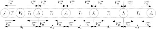
Figure 6: Signal flow diagram for stepped cavity.
Here, the node represents the stepped structure. The corresponding scattering matrix is given by:
| (43) |
Here and are the admittances of electromagnetic waves propagating in the cavity 1 and cavity 2, respectively, and is the admittance of the stepped structure, which is expressed as:
| (45) | |
| (46) | |
| (47) |
The voltage at and can be calculated as and . Similarly, the SE of the stepped cavity can be determined using this proposed hybrid analytical algorithm.
The geometric model of the series-parallel hybrid cascaded three-layer cavity is shown in Fig. 7. Cavity 1 has a height of b, while cavity 2 and cavity 3 are arranged in a parallel configuration, with heights of and . The corresponding equivalent circuit model and signal flow diagram are shown in Figs. 8 and 9.
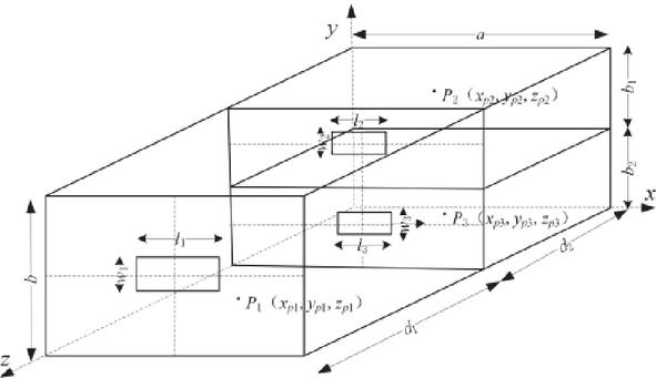
Figure 7: Geometric modeling for series-parallel hybrid cascaded three-layer cavity.
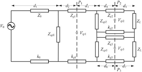
Figure 8: Equivalent circuit for series-parallel hybrid cascaded three-layer cavity.
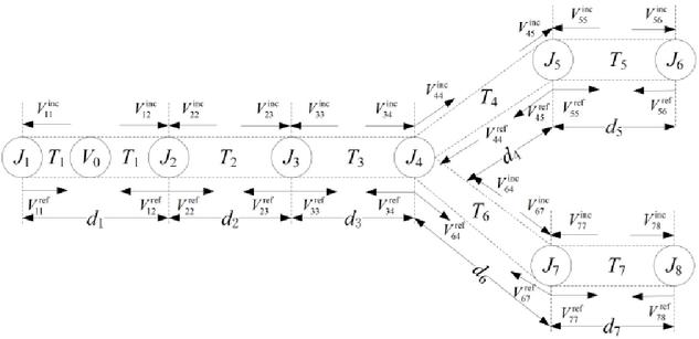
Figure 9: Signal flow diagram for series-parallel hybrid cascaded three-layer cavity.
In the signal flow diagram, node represents the two apertures of cavity 2 and cavity 3 and is modeled as a three-port network. Node corresponds to the observation point in cavity 2, while node represents the bottom of cavity 2. Similarly, node corresponds to the observation point in cavity 3, and node represents the bottom of cavity 3. The calculation method for the scattering matrices associated with each node remains unchanged. The scattering matrix corresponding to node is given by:
| (51) | |
| (53) | |
| (54) | |
| (55) | |
| (57) | |
| (58) | |
Here , , and represent the admittances of electromagnetic waves propagating in cavity 1, cavity 2, and cavity 3, while and denote the admittances of the apertures in cavity 2 and cavity 3.
The propagation coefficients, denoted by , , and , are the same as those previously described, while the expressions for and are:
| (67) | |
| (70) |
Here and denote the propagation constants in cavity 2 and cavity 3.
The voltage at is , the voltage at is , and the voltage at is . Similarly, the SE of the series-parallel hybrid cascaded shielded cavity can be calculated using this proposed hybrid analytical algorithm.
III. NUMERICAL VERIFICATION
To validate the hybrid analytical method proposed in this study, several cavity models were designed to perform numerical verification of the SE. Comparisons and analyses between the results of the proposed method and those from CST simulations were carried out to confirm the reliability of this method.
The cavity models were fabricated from a lossy conducting material with a magnetic permeability of 1.2610-6 H/m and an electrical conductivity of S/m. The thickness of the walls was set as mm. The incident plane-wave angles were specified as , , and , whereby the wave is incident perpendicularly to the aperture plane along the direction. The frequency range investigated spans from 0.1 to 3 GHz. The cavity dimensions, aperture dimensions, aperture positions, and observation point positions used in the models are summarized in Table 1.
Table 1: Parameter settings for calculation cases
| Case No. | Cavity Dimensions (mm) | Aperture Dimensions (mm) | Aperture | Observation |
| Positions | Point | |||
| (mm) | Positions (mm) | |||
| 1 | (55,140,85) | |||
| 2 | array, Each aperture:20 , Spacing:4 | (225,140,255) | ||
| 3 | Cavity 1: Cavity 2: |
(45,90,155) | ||
| 4 | Cavity 1: Cavity 2: |
array, Each aperture:20 , Spacing: 4 | (150,60,120) | |
| 5 | Cavity 1: | |||
| Cavity 2: | ||||
| Cavity |
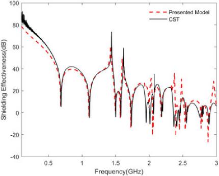
Figure 10: SE results of Case 1.
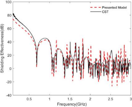
Figure 11: SE results of Case 2.
Figure 10 presents the results for Case 1, the observation point lies at the top-left corner. The results demonstrate that the method enables accurate prediction of SE at eccentric locations, with excellent agreement between the analytical approach and CST simulations.
Figure 11 presents the results for Case 2, the aperture configuration consists of a 33 eccentric square aperture array. Due to the increased complexity of the aperture geometry, more modes must be considered compared to a single aperture, which results in additional resonance peaks. The analytical results from the proposed method exhibit a high degree of agreement with CST simulation results in both amplitude and resonant frequencies. These results demonstrate that the proposed method can accurately address both central aperture and eccentric aperture array configurations, enabling reliable calculation of SE and identification of resonant points for eccentric observationpoints.
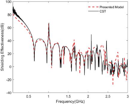
Figure 12: SE results of Case 3.
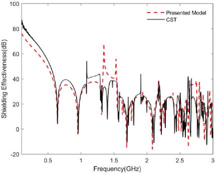
Figure 13: SE results of Case 4.
Figure 12 presents the results for Case 3 of the stepped cavity. In this case, the eccentric aperture is situated at the bottom-right corner. The results derived from the method proposed herein display strong consistency with CST simulation results in both amplitude and resonant frequencies, which effectively validates the accuracy of the method when extended to stepped cavities with eccentric apertures.
Figure 13 presents the results for Case 4 of the stepped cavity, The aperture configuration consists of a 22 eccentric square aperture array, with the observation point situated along the central axis of Cavity 2. These results demonstrate that this method can accurately predict the SE for stepped cavities with eccentric aperture arrays, which further confirms its applicability to complex aperture configurations.
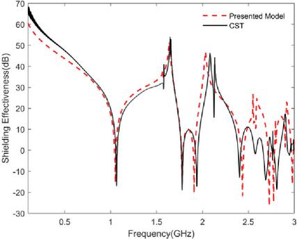
Figure 14: SE results of Case 5 point .
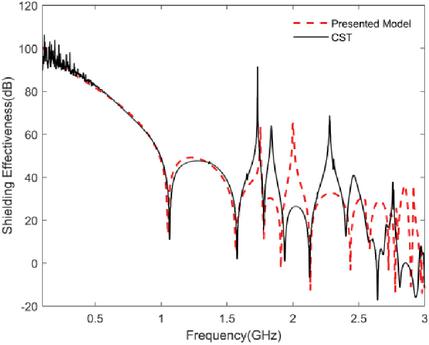
Figure 15: SE results of Case 5 point .
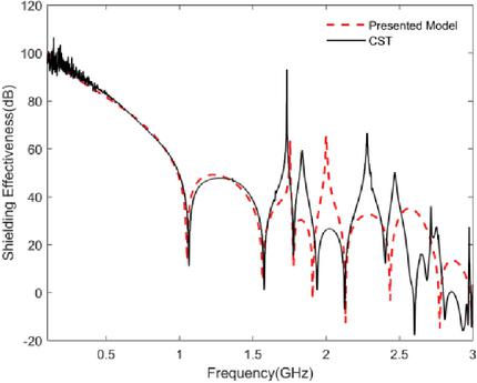
Figure 16: SE results of Case 5 point .
Figures 14, 15, and 16 present the results for Case 5 of the series-parallel hybrid cascaded three-layer cavity, findings from the proposed method exhibit strong agreement with CST simulation results in both amplitude and resonant frequencies, indicating that the method is suitable for calculating the SE of complex cavity structures. However, as the frequency increases, the discrepancy between the calculated and simulated results becomes more pronounced, though the overall trend remains consistent. Additionally, since cavity 2 and cavity 3 are arranged in parallel, their SE and resonant frequencies are identical if their aperture sizes and observation point positions are the same. Furthermore, the inner cavity exhibits resonances corresponding to those of the outer cavity. This is attributed to the higher energy levels in the outer cavity at its resonant frequencies, which, when coupled to the inner cavity, cause a reduction in the SE in the inner cavity at those frequencies.
All numeric calculations were carried out on one computer, fitted with Intel Core i3-10110U CPU @2.10 GHz and 8 GB of RAM. The proposed hybrid analytical method took no more than 20 seconds per calculation, whereas the corresponding CST simulations took more than 20 minutes. This substantial reduction in computation time highlights the distinct advantage of the proposed method in terms of computational efficiency.
IV. CONCLUSION
This paper presents a hybrid analytical method that integrates the equivalent circuit method, electromagnetic topology theory, and generalized BLT equations, while systematically accounting for plane-wave incidence-angle effects and lossy conducting material properties. The approach enables rapid evaluation of both the SE and the resonant behavior of lossy metallic cavities. Compared with the results from CST simulations, the method exhibits excellent performance in both accuracy and computational efficiency. By introducing aperture and observation point position factors, the method is applicable to arbitrarily eccentric apertures, aperture arrays, and arbitrarily positioned observation points. Even at elevated frequencies, the method can quickly and accurately predict the SE and higher-order resonant frequencies. Furthermore, the proposed hybrid analytical method has been successfully extended to various complex cavity structures, including stepped cavities and series-parallel hybrid cascaded three-layer cavities, thus demonstrating its broad applicability for SE analysis in complex cavity configurations. This work provides a simple and efficient approach for SE calculations in complex shielding structures, and numerical validation via CST simulations has confirmed its efficacy. Future work will focus on experimental validation to further corroborate these numerical findings.
ACKNOWLEDGMENT
This work was supported by the National Natural Science Foundation of China (Grant 51375490).
REFERENCES
[1] P. Radhakrishnan, L. Koraqi, T. Claeys, J. Catrysse, and D. Pissoort, “FDTD simulation and experimental comparative study of a Gasket’s shielding effectiveness characterization: Dipole Vs. log-periodic antenna,” IEEE Trans. Electromagn. Compat., vol. 67, no. 2, pp. 598–608, Apr. 2025.
[2] Y. A. Medjaouri, K. Benzaoui, A. Ales, B. Rekioua, R. Tahmi, D. Peumans, J. Gyselinck, and Y. Rolain, “Equivalent modeling of multilayered conductive composite materials for EMI shielding applications,” IEEE Trans. Dielectr. Electr. Insul., vol. 32, no. 4, pp. 1923–1929, Aug. 2025.
[3] M. Kalantari and S. H. H. Sadeghi, “An efficient method for computing the shielding effectiveness of arbitrary-shape multilayered composite enclosures,” IEEE Trans. Electromagn. Compat., vol. 66, no. 2, pp. 444–452, Apr. 2024.
[4] Z. Sun, W. Dong, D. Qin, L. Zheng, P. Qiu, C. Ding, X. Yang, and C. Jiao, “Approximate simulation of low frequency magnetic shielding of a rectangular shielding box with all walls perforated periodical holes,” Prog. Electromagn. Res. Lett., vol. 109, pp. 31–39, Feb. 2023.
[5] M. P. Robinson, J. D. Turner, D. W. P. Thomas, J. F. Dawson, M. D. Ganley, A. C. Marvin, S. J. Porter, T. M. Benson, and C. Christopoulos, “Shielding effectiveness of a rectangular enclosure with a rectangular aperture,” Electron. Lett., vol. 32, no. 17, pp. 1559–1560, Aug. 1996.
[6] A. Rabat, P. Bonnet, K. E. K. Drissi, and S. Girard, “Analytical models for electromagnetic coupling of an open metallic shield containing a loaded wire,” IEEE Trans. Electromagn. Compat., vol. 59, no. 5, pp. 1634–1637, Oct. 2017.
[7] S. Shen, Y. Wang, and P. Xing, “The prediction of shielding effectiveness of the rectangular enclosure with complex apertures based on the BLT equation,” IEICE Electron. Express, vol. 22, no. 10, pp. 20250159-20250159, May 2025.
[8] M. C. Yin and P. A. Du, “An improved circuit model for the prediction of the shielding effectiveness and resonances of an enclosure with apertures,” IEEE Trans. Electromagn. Compat., vol. 58, no. 2, pp. 448–456, Apr. 2016.
[9] B. L. Nie, P. A. Du, and P. Xiao, “An improved circuital method for the prediction of shielding effectiveness of an enclosure with apertures excited by a plane wave,” IEEE Trans. Electromagn. Compat., vol. 60, no. 5, pp. 1376–1383, Oct.2018.
[10] Y. Gong, Y. Li, and L. Jiang, “Efficient analytical method for the shielding effectiveness of an apertured enclosure based on the BLT equation,” IET Sci. Meas. Technol., vol. 14, no. 8, pp. 897–904, Sep. 2020.
[11] W. Shen, S. Wang, W. Li, H. Jin, and H. Zhang, “An extended hybrid analytical model for the shielding effectiveness prediction of a multi-cavity structure with numerous apertures,” Prog. Electromagn. Res. M., vol. 96, pp. 181–190, Sep. 2020.
[12] H. Jin, H. Zhang, Y. Ma, K. Chen, and X. Sun, “An analytical hybrid model for the shielding effectiveness evaluation of a dual-cavity structure with an aperture array,” Prog. Electromagn. Res. Lett., vol. 91, pp. 109–116, May 2020.
[13] J. Ren, Y. Pan, Z. Zhou, and T. Zhang, “Research on testing method for shielding effectiveness of irregular cavity based on field distribution characteristics,” Electronics, vol. 12, no. 4, p. 1035, Feb. 2023.
[14] K. Chen, H. Jin, H. Zhang, X. Zhang, and Z. Liu, “A hybrid analytical model for estimating the shielding effectiveness of an irregular cavity structure with aperture arrays,” in 22nd International Symposium on High Voltage Engineering (ISH 2021) Hybrid Conference, Xi’an, China, pp. 949–954, 2021.
[15] J. C. Zhou and X. T. Wang, “An efficient method for predicting the shielding effectiveness of an apertured enclosure with an interior enclosure based on electromagnetic topology,” Applied Computational Electromagnetics Society (ACES) Journal, vol. 37, no. 10, pp. 1014–1020, Oct. 2022.
[16] J. Shim, D. G. Kam, J. H. Kwon, and J. Kim, “Circuital modeling and measurement of shielding effectiveness against oblique incident plane wave on apertures in multiple sides of rectangular enclosure,” IEEE Trans Electromagn. Compat., vol. 52, no. 3, pp. 566–577, Aug. 2010.
BIOGRAPHIES

Ai-Guo Gao was born in Lianyungang, Jiangsu Province, China, in 1984. He received his B.S. degree in communication engineering from Ocean University of China, Qingdao, in 2007, and the M.S. degree in Communication and Information Systems from Naval University of Engineering, Wuhan, in 2009. He is currently working toward the Ph.D. degree in Aerospace Science and Technology with Naval Aviation University, Yantai, China. His research interests include electromagnetic shielding and electromagnetic compatibility technology.

Da-Zhao Yu was born in Yuncheng, Shandong Province, China, in 1976. He received his Ph.D. degree from Naval Aviation University, Yantai, in 2008. He is currently a Professor with the School of Basic Sciences for Aviation, Naval Aviation University. His research interests include flight safety, electromagnetic compatibility measurement, and corrosion protection and control.

Yi-Jiang Du was born in Jincheng, Shanxi Province, China, in 1989. He received his M.S. degree from Beihang University, Beijing, in 2018. He is currently a Lecturer with the School of Basic Sciences for Aviation, Naval Aviation University. His research interests include flight mechanics and flight control.

He-Xiang Huang was born in Wuhan, Hubei Province, China, in 2001. He is currently working toward the M.S. degree in Aerospace Science and Technology with Naval Aviation University, Yantai. His research interests include electromagnetic compatibility modeling and testing techniques.
ACES JOURNAL, Vol. 40, No. 11, 1116–1125
DOI: 10.13052/2025.ACES.J.401108
© 2025 River Publishers