Multi-Objective Optimization of a Rectangular Structured Linear, Actuator Based on Taguchi Method
Muhammad Jawad1, Haitao Yu1, Fariba Farrokh2, and Zahoor Ahmad3
1School of Electrical Engineering, Southeast University, Nanjing, Jiangsu 210096, China, m.jawad35@yahoo.com, htyu@seu.edu.cn
2Faculty of Electrical Engineering, Shahid Beheshti University Tehran, Iran, f_farrokh@sbu.ac.ir
3Department of Electrical Power Engineering and Mechatronics, Tallinn University of Technology, Tallinn 19086, Estonia, zahoor.ahmad@taltech.ee
Submitted On: August 21, 2025; Accepted On: January 14, 2026
Abstract
This paper introduces an innovative rectangular structured Linear Oscillating Machine (LOM) featuring an innovative arrangement of permanent magnets (PMs) which are positioned on the mover. A sinusoidal magnet arrangement (SMA) is chosen to minimize PM materials while ensuring the performance parameter, in terms of electromagnetic force, remains unaffected. The focus of the design is to reduce the cogging force and enhance the electromagnetic force to the PM mass ratio. The optimization is accomplished by utilizing design-of-experiment (DOE) Taguchi method optimization for a linear actuator, along with the finite element method (FEM). A multi-objective optimization approach is employed to refine the parameters of the linear actuator, focusing on the maximum force, the force-to-PM-weight ratio, and minimizing cogging force. By identifying the most effective parameters, an appropriate case with high sensitivity and accuracy is selected. The output parameters, like electromagnetic force and stroke of the proposed optimization approach, score very well, while the design is simply structured due to the utilization of a rectangular structured core part. The proposed design significantly reduces the cogging force to an exceptionally low level, enhancing performance and reliability.
Keywords: Cogging force reduction, sinusoidal magnet arrangement, Taguchi method of optimization..
1 INTRODUCTION
The Linear Oscillating Machine (LOM) offers an innovative solution for enabling pistons to move back and forth along a single axis without the complexity of screws, gears, or crankshafts. By producing linear oscillatory motion directly within the piston, LOM streamlines the mechanism and eliminates the need for converting rotary motion into linear oscillation. This makes LOM a highly effective alternative for applications that traditionally utilize rotary motors, enhancing efficiency and reducing mechanical complexity [1, 2, 3, 4, 5, 6]. The advantages of LOA include a higher oscillation frequency, reduced power consumption, and lower fabrication costs. LOM performs optimally when operated at its resonance frequency, where the excitation frequency aligns perfectly with the mechanical resonance frequency. Under resonance conditions, the armature requires minimal electrical current, which reduces input power while maintaining the same output power, thereby enhancing the system’s efficiency [7, 8, 9].
Cogging force plays an essential role in the design of conventional PM linear motors. As a result, many innovative methods have been introduced to enhance the accuracy and speed of detent force calculations. These advancements contribute significantly to the optimization of motor performance [10]. The first optimized linear actuator [11] was developed by utilizing design-of-experiment (DOE) and response surface method (RSM) techniques. This approach helps verify the effectiveness of the initial design and enhances its performance characteristics, including output power and compactness. Following this [12], space mapping, manifold mapping, and optimization were implemented for linear actuators. While a Maxwell stress tensor analysis has been applied to the linear actuator, it tends to increase calculation time due to the complexity and nonlinearity of the equations involved [13]. The Taguchi method has been established as the most effective optimization technique for assessing influential parameters. Research has shown that multi-objective optimization can efficiently identify the key factors affecting electric machines in a short amount of time [14, 15, 16]. The inductance-based analytical model in [17] highlights the importance of accurate field prediction in PM linear machines.
Recent research has shown that the Taguchi DOE method is an efficient and reliable tool for optimizing electromagnetic devices with multiple interacting parameters [18]. Reference [19] employed a comprehensive Taguchi-based framework to optimize a coaxial magnetic coupling, demonstrating its ability to reduce computational effort while accurately identifying dominant design variables. Likewise, [19] applied the Taguchi method to optimize an outer-rotor double-PM flux-switching generator, validating the optimized design experimentally and confirming the method’s effectiveness in multi-objective performance improvement. Together, these works highlight the suitability of the Taguchi approach for systematic and statistically grounded optimization of complex electrical machine structures.
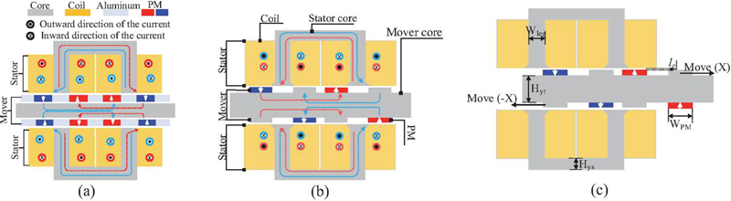
Figure 1 Topology of the linear actuator: (a) conventional design of the actuator [2], (b) proposed SMA design of the actuator, and (c) optimization parameters of the proposed SMA design of the actuator.
The main purpose of this paper is to design an optimized linear actuator. The focus is on reducing costs and enhancing the electromagnetic performance of the linear actuator, making it suitable for implementation in conventional actuator structures. The key contributions of this paper include a novel topology that introduces a sinusoidal magnet arrangement (SMA) in the mover for the first time. A new technique of optimization is adopted to optimize the performance. This technique aims to achieve multi-objective optimization, addressing factors such as maximum force, improving the force-to-permanent magnet weight ratio, and minimizing cogging force, all using the Taguchi method. The highlights of this paper are:
(1) The proposal features a linear actuator with an SMA, focusing on low cost and minimum PM material utilization.
(2) DOE optimization utilizing the Taguchi method identifies influential parameters efficiently.
(3) The optimization process adopts a multi-objective approach for a comprehensive outcome.
2 DESIGN AND OPERATING PRINCIPLE
Figure 1 (a) presents a benchmark mark design of the proposed SMA design of the actuator, included to illustrate its significance. The proposed SMA design of the actuator shown in Fig. 1 (b) delivers an identical electromagnetic force while utilizing 50% of the PM materials.
The investigated SMA design includes a C-shaped stator core with a rectangular structure. Coils are wound around both legs of the C-shaped stator core as shown in Figs. 1 (b) and (c). The currents in the coils are arranged to flow in opposite directions, causing the magnetic flux to combine and enter the rotor core. This setup is also adopted for the coils of another stator. The mover is composed of core materials and PMs, which are placed in a sinusoidal pattern. The design parameters are clearly outlined in Table 1.
Table 1 Parameters of the linear actuator
| Parameter | Initial | Optimized |
| Value | Value | |
| Height of the actuator [mm] | 100 | 102 |
| Depth of the actuator [mm] | 120 | |
| Rotor yoke height [mm] | 16 | |
| PM length [mm] | 4 | 3.8 |
| PM width (WPM) [mm] | 15 | 14 |
| Stator yoke height (Hys) [mm] | 7 | 8 |
| Height of the pole shoe [mm] | 4 | |
| Length of the pole shoe [mm] | 4 | |
| Air gap (lg) [mm] | 1 | 1.2 |
| Coil width [mm] | 20 | |
| Coil height [mm] | 30 | |
| Stator leg [mm] | 10 |
The proposed SMA design operates using single-phase alternating current (AC). During one half-cycle of the AC, the mover adjusts its position to one extreme, providing the least reluctant path for the magnetic flux. During the remaining half cycle of the AC, the mover shifts to the opposite extreme. By maintaining a continuous supply of AC, the mover experiences a linear oscillatory electromagnetic force.
3 MULTI-OBJECTIVE DOE/OPTIMIZATION METHOD
The Taguchi method, a DOE technique, is here applied for the first time to identify effective parameters in linear actuator characteristics. Known for its effectiveness in optimizing electrical machines, the method uses fractional factorial experiments arranged in an “Orthogonal Array.” This structure ensures an even distribution of parameter levels across columns and symmetrical combinations for each pair of columns. While the Taguchi method yields optimization results, they may not always be optimal. Increasing the levels of each variable can improve accuracy, but it can also be inefficient and time-consuming. The main goal of this approach is to pinpoint the effective parameters. To comprehensively evaluate the optimization effect of the linear actuator, the overall process is divided into three levels. The structural parameters of both the stator and rotor (shown in Fig. 2) are optimized independently using an improved iterative Taguchi method combined with sensitivity analysis, as illustrated in Fig. 2.
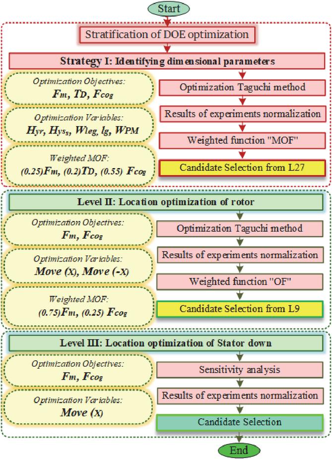
Figure 2 Flowchart of multi-objective stratification of DOE optimization.
As clearly illustrated in Fig. 2, the optimization procedure is generally carried out in three main stages. The proposed optimization framework integrates the Taguchi method with sensitivity analysis. The primary objective is to systematically identify the influential parameters and evaluate their effects step by step, ensuring a purposeful and targeted optimization process.
In the first stage, the goal is to optimize the geometric dimensions based on three main performance criteria: maximum force, maximum force-to-magnet-weight ratio, and cogging force. Five geometric parameters were examined in this phase, and only the Taguchi method was employed.
The second stage aims to determine the optimal rotor position for start-up. In this phase, the Taguchi method was again applied to optimize two objectives (maximum force and cogging force) at two different magnet positions. By the end of this stage, both the geometry and the rotor position were optimized using the minimum required amount of magnet material.
In the final stage, the position of the second stator was relevant only to the two objectives from the second stage. Sensitivity analysis was therefore used to evaluate and optimize this parameter. The detailed step-by-step implementation of the proposed methodology is comprehensively described in the following section.
3.1 Layer I: Optimization of geometric parameters
To improve the working stability of the linear actuator, the maximum force, the force-to-permanent PM weight ratio, and minimizing cogging force are selected as the primary optimization objectives.
Table 2 Combinations of variables using the Taguchi method of optimization
| Exp. | (mm) | (mm) | (mm) | (mm) | (mm) | (N) | (N/Kg) | (N) | OF |
| 1 | 14 | 7 | 10 | 0.8 | 14 | 0.94 | 0.75 | 0.81 | 0.83 |
| 2 | 14 | 7 | 10 | 0.8 | 15 | 0.88 | 0.66 | 0.78 | 0.788 |
| 3 | 14 | 7 | 10 | 0.8 | 16 | 0.87 | 0.61 | 0.81 | 0.785 |
| 4 | 14 | 8 | 11 | 1 | 14 | 0.917 | 0.66 | 0.66 | 0.72 |
| 5 | 14 | 8 | 11 | 1 | 15 | 0.983 | 0.765 | 0.561 | 0.707 |
| 6 | 14 | 8 | 11 | 1 | 16 | 0.956 | 0.692 | 0.598 | 0.706 |
| 7 | 14 | 9 | 12 | 1.2 | 14 | 0.844 | 0.739 | 0.779 | 0.787 |
| 8 | 14 | 9 | 12 | 1.2 | 15 | 0.883 | 0.713 | 0.776 | 0.79 |
| 9 | 14 | 9 | 12 | 1.2 | 16 | 0.870 | 0.652 | 0.778 | 0.775 |
| 10 | 15 | 7 | 11 | 1.2 | 14 | 0.812 | 0.775 | 0.782 | 0.789 |
| 11 | 15 | 7 | 11 | 1.2 | 15 | 0.797 | 0.728 | 0.758 | 0.762 |
| 12 | 15 | 7 | 11 | 1.2 | 16 | 0.806 | 0.677 | 0.771 | 0.761 |
| 13 | 15 | 8 | 12 | 0.8 | 14 | 0.999 | 0.875 | 0.575 | 0.741 |
| 14 | 15 | 8 | 12 | 0.8 | 15 | 0.999 | 0.807 | 0.437 | 0.652 |
| 15 | 15 | 8 | 12 | 0.8 | 16 | 0.999 | 0.777 | 0.503 | 0.682 |
| 16 | 15 | 9 | 10 | 1 | 14 | 0.905 | 0.826 | 0.914 | 0.894 |
| 17 | 15 | 9 | 10 | 1 | 15 | 0.879 | 0.769 | 0.895 | 0.866 |
| 18 | 15 | 9 | 10 | 1 | 16 | 0.841 | 0.679 | 0.880 | 0.83 |
| 19 | 16 | 7 | 12 | 1 | 14 | 0.675 | 0.709 | 0.971 | 0.845 |
| 20 | 16 | 7 | 12 | 1 | 15 | 0.679 | 0.648 | 0.946 | 0.82 |
| 21 | 16 | 7 | 12 | 1 | 16 | 0.692 | 0.632 | 0.951 | 0.823 |
| 22 | 16 | 8 | 10 | 1.2 | 14 | 0.794 | 0.878 | 0.998 | 0.923 |
| 23 | 16 | 8 | 10 | 1.2 | 15 | 0.780 | 0.780 | 1 | 0.901 |
| 24 | 16 | 8 | 10 | 1.2 | 16 | 0.767 | 0.732 | 0.998 | 0.887 |
Figure 1 (c) shows the parameter model of the linear actuator model, and Table 2 shows the variation range of the design parameters according to the design experience and geometrical limits. The specific values for rotor yoke height , stator yoke height , stator leg , length of the air-gap (, and PM width are provided in Table 2. Three levels are considered for each variable, by selecting eight variables at three levels, the Orthogonal Array L27 is established, requiring the performance of 27 experiments. In this paper only five experiments are shown due to space constraint. The corresponding results are analyzed through the finite element method (FEM). The mean effect of various variables on the optimization responses has been assessed. Specifically, the average impact of the selected variables on the optimization responses including maximum force (), force-to-PM-weight ratio (), and cogging force () has been analyzed and illustrated in Fig. 3. Using the S/N ratio, the impact of each experiment’s parameters has been measured. Based on the optimization goal, S/N ratios are calculated as:
| (1) |
where is the number of repeats in each scenario and is the output of the scenario in th repetition. In this study, larger is better is specified as SN quality for four object optimizations to analyze the impact of maximum force, the force-to-PM-weight ratio, and minimizing cogging force. Simultaneously, it is aimed to select the one optimal level from three available options. The results of each experiment have been normalized according to:
| (2) | |
| (3) | |
| (4) |
MOF is defined as the multi-objective function, computed from normalized and weighted values of maximum electromagnetic force, cogging force, and force-to-PM-weight ratio. In a linear actuator, predicting the cogging force is essential. The cogging force is assigned a weight of 0.55, as indicated in equation (4). Next, the maximum force is prioritized with a weight of 0.25. Finally, the force-to-PM-weight ratio is given a weight of 0.2. All metrics are normalized for optimization purposes.
In this regard, Table 2 includes all the experiments. The parameter limits are as follows:
Table 2 displays five chosen experiments to optimize manuscript space, highlighting the normalized results for the targeted parameters. Exp. 22, which incorporates at least four parameters (, , , ) produced the most favorable outcomes. Following this, Exps. 23 and 24 showed improved results with at least three parameters (, , ). Therefore, among the 27 experiments derived from Taguchi optimization, Exp. 22 has been selected as the Layer I optimization model.
Figure 3 (a) shows the force for two linear actuators. The maximum force achieved is approximately 794.77 N for the optimized SMA model 1 and 793.52 N for the initial SMA model. Typically, optimizations aimed at reducing cogging result in a decrease in force or torque in machines. However, through multi-objective optimization and the identification of sensitive parameters, the optimal model was chosen to maintain force levels without any reduction. Figure 3 (b) illustrates the cogging force for the two models. The initial SMA model has a cogging force of 395.82 N, while the optimized SMA model 1 has a cogging force of 183.86 N. This means that the optimized SMA model exhibits a 53.5% reduction in cogging force when the winding current is zero.
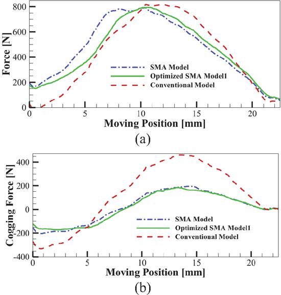
Figure 3 The force and cogging force of the conventional and SMA actuators after optimization. Layer I: (a) electromagnetic force and (b) cogging force.
3.2 Layer II: Location optimization of mover
Optimization is continued in Layer II due to the substantial cogging force achieved in the first layer. In this phase, one of the optimization objectives, specifically, the ratio of maximum force to PM weight, has been removed because the geometric parameters in the first layer have already been optimized. Instead, the focus is on optimizing the positions of the upper and lower PMs and the rotor teeth relative to one another. This is done using the Taguchi method to identify their most effective arrangements.
As a result, the optimization objectives in this layer, the targeted parameters are maximum force and minimum cogging force. To facilitate this, L9 orthogonal experiments have been conducted, employing two displacement factors for the upper and lower PMs as well as the rotor teeth. Table 3 illustrates the normalized results of these objectives.
Table 3 Variable combination according to mover’s position
| Exp. | Move (X) | Move (-X) | OF | ||
| (mm) | (mm) | (N) | (N) | ||
| 1 | 1 | 1 | 0.99 | 0.26 | 0.807 |
| 2 | 1 | 2 | 0.988 | 0.4 | 0.841 |
| 3 | 1 | 3 | 0.973 | 0.52 | 0.861 |
| 4 | 2 | 1 | 0.99 | 0.39 | 0.84 |
| 5 | 2 | 2 | 0.983 | 0.54 | 0.873 |
| 6 | 2 | 3 | 0.953 | 0.657 | 0.879 |
| 7 | 3 | 1 | 1 | 0.633 | 0.908 |
| 8 | 3 | 2 | 0.981 | 0.808 | 0.938 |
| 9 | 3 | 3 | 0.892 | 1 | 0.919 |
The maximum force is assigned to a weight of 0.75, while the cogging force is assigned a weight of 0.25. All metrics are normalized for optimization purposes. Table 3 illustrates the normalized targets for each parameter. Exp. 8, which incorporates at least two parameters, produced the most favorable outcomes. Following this,
Exp. 7 exhibited improved results in maximum force, while Exp. 9 showed enhancements in cogging torque. Therefore, among the nine experiments derived from Taguchi optimization, Exp. 8 has been selected as the optimization model for Layer II. The electromagnetic and cogging force responses of the proposed SMA topology after Layer II optimization are shown in Figs. 4 (a) and (b), respectively.
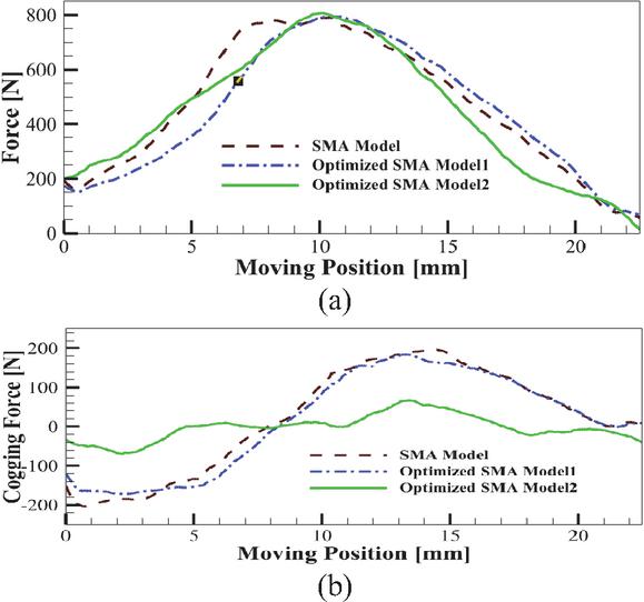
Figure 4 The force and cogging force of the conventional and SMA actuators after optimization. Layer II: (a) EM force and (b) cogging force.
3.3 Layer III: Location optimization of stator down
In Layer III, the position of the stator below the actuator, which has two stators and one central mover, significantly affects the optimization objectives. To address this, a sensitivity analysis is conducted at three different optimization levels, focusing on two objectives: maximum force and cogging force. The normalized results of this analysis are presented in Table 4. The results in Table 4 indicate that optimization was achieved in the third layer, positioning the two goals correctly.
Table 4 Variable combination according to the lower stator position relative to the upper stator
| Exp. | Move (X) | (N) | (N) |
| 1 | 1 | 1 | 1.081 |
| 2 | 2 | 0.921 | 1 |
| 3 | 3 | 0.871 | 0.628 |
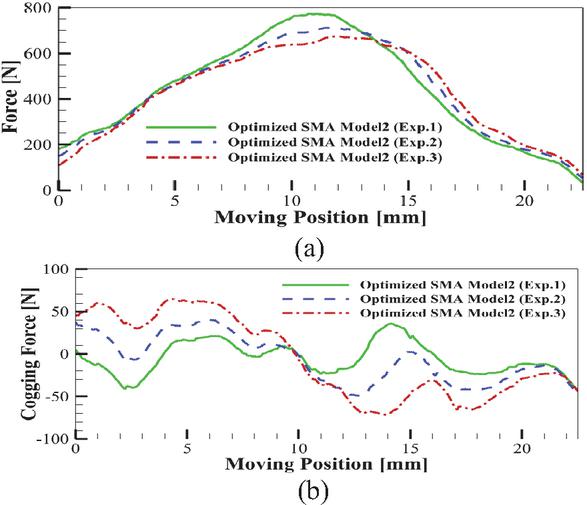
Figure 5 The force and cogging force of the conventional and SMA actuators after optimization. Layer III: (a) EM force and (b) cogging force.
The results of the last Layer III optimization are presented in Fig. 5. Exp. 1 has much better results than the other two experiments. In the three sensitivity analyses, Exp. 1 demonstrated the highest force and the lowest cogging force, which is why it has been selected as the final model.
3.4 Summary of the proposed DOE optimization
The normalized results for the targets are summarized in this section. Exp. 22, which incorporates at least four parameters () yielded the most favorable outcomes in Layer I. In Layer II, Exp. 8 demonstrated improved results with at least two parameters: Mover (x) and Mover (-x). Consequently, among the 27 experiments in Layer I and the nine experiments in Layer II derived from Taguchi optimization, Exp. 1 has been selected as the final optimization model in Layer III.
4 FEM SIMULATION AND RESULTS OF THE OPTIMIZED SMA TOPOLOGY
4.1 FEM model setup and meshing strategy
The proposed model is developed using ANSYS Maxwell, while the optimization process is performed in Minitab. A two-dimensional FEM model of the target actuator is first established in Maxwell to obtain the initial geometric dimensions for preliminary design. The linear motion of the rotor is defined using the motion setup module. An adaptive finite-element meshing strategy is employed to ensure numerical accuracy and convergence, with local mesh refinement applied to critical regions such as the air gap which passes the permanent magnets (PMs), rotor edges, and areas with high magnetic field gradients. In particular, the air-gap region is discretized with a significantly finer mesh to accurately capture flux-density variations and electromagnetic flux during linear motion.
Mesh quality is controlled by limiting element aspect ratios and enforcing minimum element sizes in sensitive regions. A mesh convergence study is conducted to verify that further refinement does not significantly affect key electromagnetic quantities, including flux density, force, and induced voltage.
The initial actuator dimensions and multi-objective optimization goals are processed in Minitab using a multi-stage Taguchi-based DOE approach. Sensitivity analyses identify the most influential parameters at each optimization stage, and these parameters are directly applied to the Maxwell FEM model. Consequently, an effective multi-stage and multi-objective optimization is achieved, and the corresponding FEM simulation results are presented in sections B and C.
4.2 Flux density distribution and field analysis
The flux density and flux lines of the proposed SMA topology is illustrated in Figs. 6 (a) and (b). The FEM results indicate that the optimized SMA linear actuator does not experience significant magnetic saturation. According to the basic operating principle of a linear actuator, the mover moves to a position where the magnetic flux forms a complete closed path with minimal reluctance. From Fig. 6, the magnetic flux path is completed at extreme mover positions.
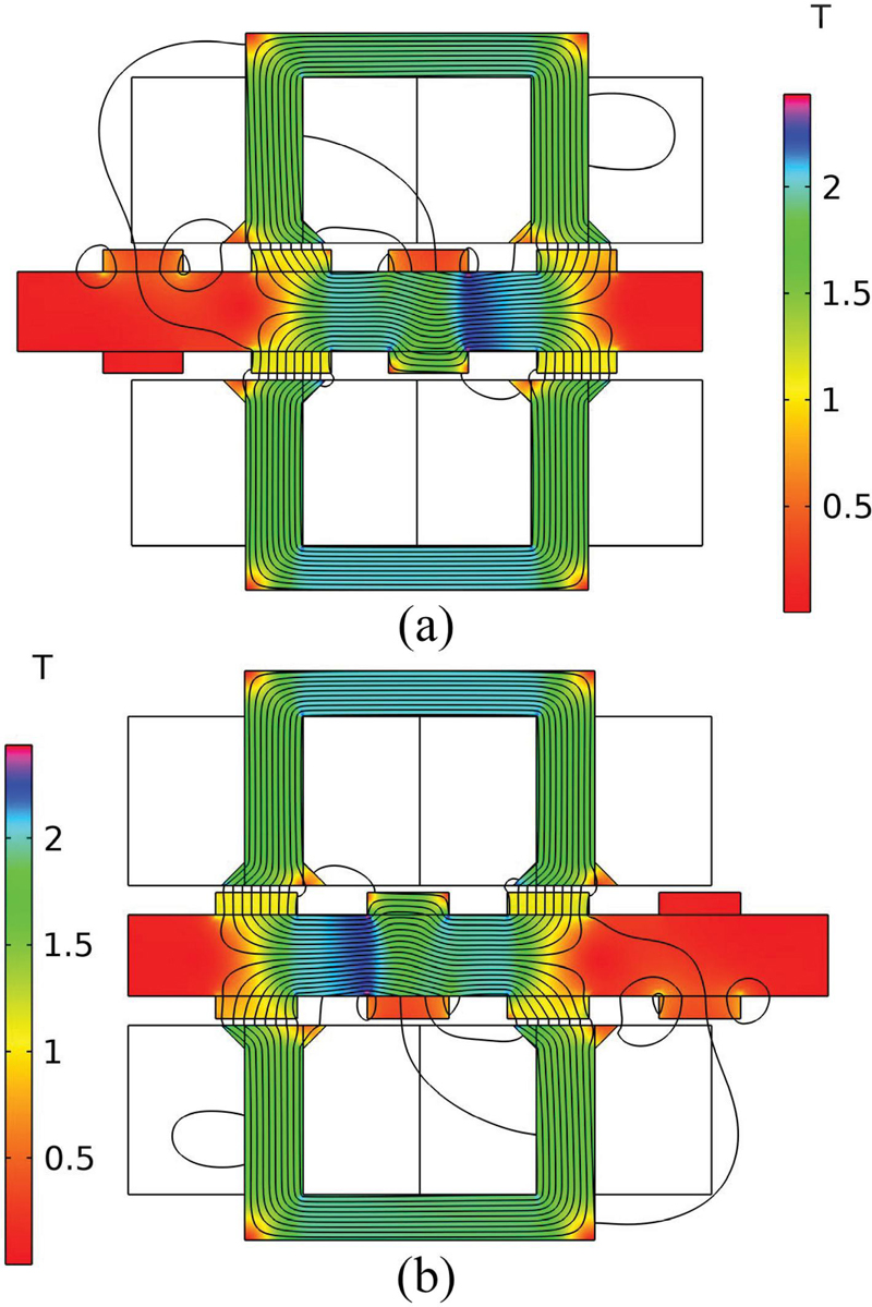
Figure 6 Flux density distribution and flux lines for the SMA linear actuator at alternate extreme mover positions (a) left extreme mover position, (b) right extreme mover position.
4.3 Electromagnetic and cogging force results
Figures 7 (a) and (b) show the EM force and cogging force of the conventional design of the actuator and the proposed SMA actuators, respectively. In the optimized SMA model, the maximum force decreased by 2.53% compared to the initial model and by compared to the conventional model. Additionally, the cogging force is reduced in the optimized SMA model, with a decrease of compared to the initial model and compared to the conventional model. Additionally, the proposed SMA design utilizes around 50% PM materials compared to the conventional design of the actuator.
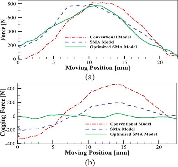
Figure 7 Force and cogging force of the conventional, SMA, and optimized SMA actuators models. (a) Electromagnetic force and (b) cogging force.
5 CONCLUSION
The LOM’s rectangular structure and sinusoidal arrangement have halved magnet costs compared to traditional designs. Using the Taguchi DOE optimization strategy, key parameters were targeted across three layers. The optimized LOM shows over reduction in cogging force and 50% cost savings of the PMs due to comprehensive multi-objective optimization. In addition, the proposed design provides a concept of designing a rectangular topology, an alternative design concept to the conventional tubular topology. The main significance that can be achieved is the fabrication of a laminated core structure. Moreover, the cost of the rectangular PM is lower than that of the tubular PM. Furthermore, in the case of the rectangular PM, the desired dimension can be conveniently achieved by attaching numerous small PMs. The proposed SMA linear actuator is a structurally simple, low-cost, and produces feasible output parameters such as electromagnetic force and stroke.
This study has been validated through comprehensive FEM simulations; however, experimental verification has not yet been performed. As part of our future work, we plan to develop an analytical model based on a magnetic equivalent circuit (MEC) formulation to complement the FEM results. Furthermore, a prototype of the proposed linear actuator will be fabricated, and experimental measurements will be carried out to validate the analytical and numerical results.
ACKNOWLEDGEMENT
This work is supported by Haitao Yu.
References
[1] A. Hassan, A. Bijanzad, and I. Lazoglu, “Dynamic analysis of a novel moving magnet linear actuator,” IEEE Transactions on Industrial Electronics, vol. 64, no. 5, 2017.
[2] M. Jawad, H. Yu, Z. Ahmad, B. Ullah, and B. Alghamdi, “Design optimization and resonance analysis of rectangular structured moving magnet linear actuator,” IEEE Access, vol. 11, 2023.
[3] S. Khalid, F. Khan, B. Ullah, Z. Ahmad, and S. Akbar, “Review of moving magnet linear oscillating actuators for linear compressor application,” 2023.
[4] Z. Ahmad, B. Ullah, F. Khan, S. Ullah, and I. Sami, “Electromagnetic performance investigation of rectangular-structured linear actuator with end ferromagnetic poles,” Energies (Basel), vol. 16, no. 15, 2023.
[5] H. Zhang, Z. Xu, L. Jin, J. Leng, H. Yu, Z. Shen, B. Ye, and S, Fang, “Electromagnetic calculation of tubular permanent magnet linear oscillation actuator considering corrected air gap permeance,” IEEE Trans Magn, vol. 59, no. 5, 2023.
[6] H. Zhang, “Detent force reduction design for the C-core single-phase permanent magnet linear oscillation actuator,” in IEEE Transactions on Industry Applications, 2023.
[7] Z. Ahmad, A. Kallaste, T. Vaimann, and M. U. Sardar, “Design and resonance analysis of tubular structured dual stator linear oscillating actuator,” in 2024 International Conference on Electrical Machines, ICEM 2024, Institute of Electrical and Electronics Engineers Inc., 2024.
[8] S. Khalid, F. Khan, B. Ullah, Z. Ahmad, A. H. Milyani, and S. Alghamdi, “Electromagnetic and experimental analyses of a low-cost miniature tubular moving magnet linear oscillating actuator for miniature compressor applications,” IET Electr Power Appl, vol. 17, no. 1, 2023.
[9] M. Jawad, Y. Haitao, Z. Ahmad, and Y. Liu, “Design and analysis of a novel linear oscillating actuator with dual stator rectangular geometry,” Appl Comput Electromagn Soc J, vol. 36, no. 10, 2021.
[10] H. Zhang, “Electromagnetic design of single-phase permanent magnet linear oscillation actuator considering detent force minimum,” IEEE Trans Magn, vol. 58, no. 8, 2022.
[11] D. J. Lee, K. S. Woo, N. C. Park, and Y. P. Park, “Design and optimization of a linear actuator for subminiature optical storage devices,” IEEE Trans Magn, vol. 41, no. 2, 2005.
[12] D. Echeverría, D. Lahaye, L. Encica, E. A. Lomonova, P. W. Hemker, and A. J. A. Vandenput, “Manifold-mapping optimization applied to linear actuator design,” IEEE Trans Magn, vol. 42, no. 4, 2006.
[13] J. Lee, E. M. Dede, D. Banerjee, and H. Iizuka, “Magnetic force enhancement in a linear actuator by air-gap magnetic field distribution optimization and design,” Finite Elements in Analysis and Design, vol. 58, 2012.
[14] Z. Xing, X. Wang, W. Zhao, X. Li, L. Xiong, and X. Zhang, “Optimization design of interior permanent magnet synchronous motor with u-shaped rotor for low-level torque ripple and electromagnetic vibration,” IEEE Transactions on Transportation Electrification, vol. 10, no. 1, 2024.
[15] Z. Shi, X. Sun, Y. Cai, and Z. Yang, “Robust design optimization of a five-phase PM hub motor for fault-tolerant operation based on taguchi method,” IEEE Transactions on Energy Conversion, vol. 35, no. 4, 2020.
[16] J. He, G. Li, R. Zhou, and Q. Wang, “Optimization of permanent-magnet spherical motor based on Taguchi method,” IEEE Trans Magn, vol. 56, no. 2, 2020
[17] E. Yucel, M. Mutluer, and M. Çunkaş, “Analysis and design of a permanent magnet linear synchronous motor based on inductance calculation,” Archives of Electrical Engineering, vol. 74, no. 4, pp. 773–794, 2025.
[18] F. Farrokh, A. Ghaheri, and E. Afjei, “A comprehensive DOE-optimization method of coaxial magnetic coupling for aircraft applications,” 2024 4th International Conference on Electrical Machines and Drives (ICEMD), Tehran, Iran, Islamic Republic of, pp. 1–6, 2024.
[19] M. Farahzadi, S. Ali, S. Mirnikjoo, K. Abbaszadeh, F. Marignetti, and M. Salehi, “Design and experimental validation of a new outer rotor double PM excited flux switching generator for direct drive wind turbines,” in IEEE Access, vol. 12, pp. 62256–62267, 2024.
Biographies

Muhammad Jawad was born in Pakistan in 1993. He received his Bachelor of Science degree in Electrical Engineering from UST Bannu in Khyber Pakhtunkhwa, Pakistan, in 2016. He subsequently pursued advanced studies at Southeast University in Nanjing, China, where he completed his master’s degree in Electrical Engineering. Currently, he is engaged in doctoral research in Electrical Engineering at Southeast University. His research interests focus on the design of linear actuators.

Haitao Yu, Ph.D., professor, doctoral supervisor, and director of China Energy Society. He received his Ph.D. from Huazhong University of Science and Technology (HUST), China, in 1995. In 1997, he served as an associate professor in the School of Electric Engineering, and 1998–2003 he took part in academic exchange visits to Duke University and Canada. He served as editor of special issue “Ocean Power Generation” in Advances in Mechanical Engineering (SCI) and is a reviewer of various IEEE journals.

Fariba Farrokh (Student Senior Member, IEEE) received B.Sc. and M.Sc. degrees in electrical engineering in 2012 and 2014, respectively, and Ph.D. degree in electrical power engineering from Shahrood University of Technology, Shahrood, Iran, in 2024. She is currently with the Faculty of Electrical Engineering at Shahid Beheshti University, Tehran. Her research interests include electrical machine design and optimization, analytical and multi-physics modeling, demagnetization analysis, and development of high-performance permanent magnet machines for electric vehicles, renewable energy systems, and aerospace applications. Farrokh is a Student Senior Member of the IEEE, and has received several research awards, including Best Paper Presentation Award at ICEMD 2024 and Global Research Award 2025.

Zahoor Ahmad (Student Member, IEEE) was born in Khyber Pakhtunkhwa, Pakistan, in 1993. He received a B.S. degree in Electrical Engineering from the University of Science and Technology, Bannu, Khyber Pakhtunkhwa, in 2016 and an M.S. degree in Electrical Engineering from COMSATS University Islamabad at Abbottabad, Pakistan, in 2020. During his M.S. degree program, he worked on the Design and Analysis of Moving Magnet Linear Oscillating Actuators. Currently, he is pursuing a Ph.D. at Tallinn University of Technology, Department of Electrical Power Engineering and Mechatronics. His research interests include Advanced Design Methodology for Additively Manufactured Electrical Machines.
ACES JOURNAL, Vol. 41, No. 01, 1–9
DOI: 10.13052/2026.ACES.J.410101
© 2026 River Publishers