Distributed Heterogeneous Conformal Meter-Wave Phased Array Using Characteristic Mode for Airship Platform
Yuhao Feng and Zijian Yang
Department of Electronic Science and Engineering
University of Electronic Science and Technology of China, Chengdu 611731, China
yuhao.feng@uestc.edu.cn, 923679355@qq.com
Submitted On: August 29, 2025; Accepted On: October 26, 2025
ABSTRACT
This paper presents an advanced characteristic mode (CM)-based synthesis and optimization framework for designing conformal meter-wave phased array antennas on airship platforms. Unlike previous studies that focused on planar or small UAV (Unmanned Aerial Vehicle) surfaces, this work extends CM analysis to a large-scale, irregular, fully metallic airship structure in the low-frequency band. The CMs of the airship body are analyzed to extract dominant modal currents and field distributions. To achieve controllable beam scanning and polarization characteristics, a decomposition-based multi-objective evolutionary algorithm (MOEA/D) is integrated with the modal synthesis process, enabling physics-informed optimization of co-/cross-polarization energy and sidelobe level. Guided by the synthesized modal currents, distributed heterogeneous coupling elements (CEs) are conformally arranged on the platform. The fabricated 1:40 scale model demonstrates a 60∘ beam scanning range and a measured gain exceeding 10 dBi with over 80% radiation efficiency, in good agreement with simulations. The proposed method bridges CM theory and practical conformal array realization, providing a generalized approach for large-scale, platform-integrated antenna design.
Keywords: Characteristic mode (CM), distributed heterogeneous array, meter-wave, platform-integrated antenna.
I. INTRODUCTION
As a highly maneuverable platform, the aircraft carries an electronic system that can communicate with other end users at various weather, terrains, and visibility conditions [1]. To enhance gain and electronic beam scanning, antenna arrays, instead of single-element antennas, are commonly installed on the aircraft platform [2, 3]. However, designing integrated phased array antennas for aircraft presents challenges. Firstly, meter-wave phased array radar is effective for stealth and long-range detection [4, 5]. Yet, the resonant length of meter-wave antennas equals their wavelength, making it challenging to form arrays on platforms with limited space [6]. Secondly, larger antennas negatively impact aerodynamics, stability, and increase the radar cross-section (RCS) of the platform. Thirdly, platforms with complex electromagnetic materials may experience coupling issues, affecting radiation performance.
Designing conformal antenna arrays on space-constrained platforms is challenging. Current integration of platforms and antennas faces deficiencies, with electromagnetic full-wave analysis being the predominant optimization method [7]. While joint simulation reduces development time, it has limited physical explanations for antenna radiation mechanisms. Addressing these challenges, the low-frequency platform-integrated antenna design, based on the characteristic mode (CM) theory, offers advantages.
For instance, in a shipboard antenna system embedded in the platform [8], CMs synthesize radiating currents for a desired radiation pattern. Designs with multiple beam directions and consideration of polarization information offer versatile applications. In examples like [9] and [10], three beams with different directions on an aircraft platform were synthesized, and [11] achieved the switching ability of four angle beams. While some designs, like [12], focus on using polarization characteristics for incident wave detection in aircraft platforms, beam scanning is limited. In [13], coupling elements (CEs) on both sides of the platform allow 45∘ beam scanning, considering polarization characteristics and beam switch ability during CM analysis and pattern synthesis. However, not all aircraft platforms have sufficient regular edge structures for placing CEs.
Compared with existing CM-based antenna designs [9, 10, 11, 12, 13], which primarily target local or planar aircraft structures, the proposed work introduces a distributed heterogeneous conformal array framework suitable for large, irregular, and low-frequency airship platforms. First, the CM theory is extended to analyze and synthesize the global radiation modes of a fully metallic airship body, enabling efficient mode selection and field synthesis over complex surfaces. Second, a decomposition-based multi-objective evolutionary algorithm (MOEA/D) is integrated with the modal analysis to achieve physics-informed optimization of co- or cross-polarization energy, beam direction, and sidelobe control. Third, a practical conformal coupling-line excitation structure is designed according to the synthesized modal currents, realizing an experimentally validated 60∘ beam scanning with over 10 dBi gain and 80% radiation efficiency. These advancements bridge the gap between theoretical CM analysis and the engineering implementation of large-scale conformal phased arrays at meter-wave frequencies.
CM-based platform-integrated antenna research has been extensively applied in low-frequency aircraft and vehicular systems. For instance, Wang et al. [19] proposed a CM-based multiantenna system in the HF band (8–28 MHz) for aircraft platforms. Their approach achieved omnidirectional and directional radiation patterns by combining dominant modes and manually selecting exciter locations, but it was limited to discrete-frequency operation without beam scanning capability.
Subsequently, Wang et al. [20] extended this framework to the VHF band (100 MHz) and demonstrated switchable-beam array synthesis using a MOEA/D. Although effective for low-frequency flush-mounted metallic aircraft, their design required more than 10 exciters and did not consider aerodynamic constraints or scalable array realization.
In contrast, the present work proposes a closed-loop methodology that integrates platform CM analysis, multiobjective optimization, and distributed CE excitation synthesis. The use of CMs as a “hidden aperture” enables conformal array beam scanning at meter-wave frequencies without modifying the airship geometry. Furthermore, the proposed framework maintains modal continuity, physical scalability, and aerodynamic compatibility, representing a fundamental advancement beyond the HF/VHF fixed-aperture designs in [19, 20].
This article discusses designing integrated antennas for low-frequency airship platforms. Airships are ideal for long-term use in communication systems, weather forecasting, surface remote sensing, and aerial monitoring due to their cost-effectiveness.
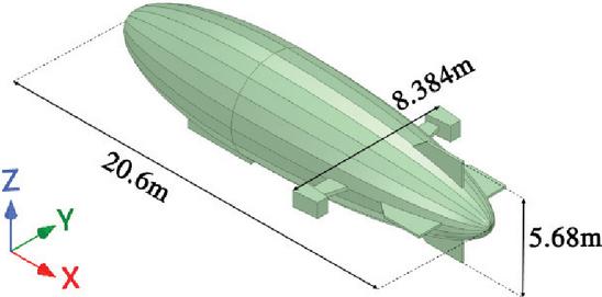
Figure 1: Geometry of a simplified airship model.
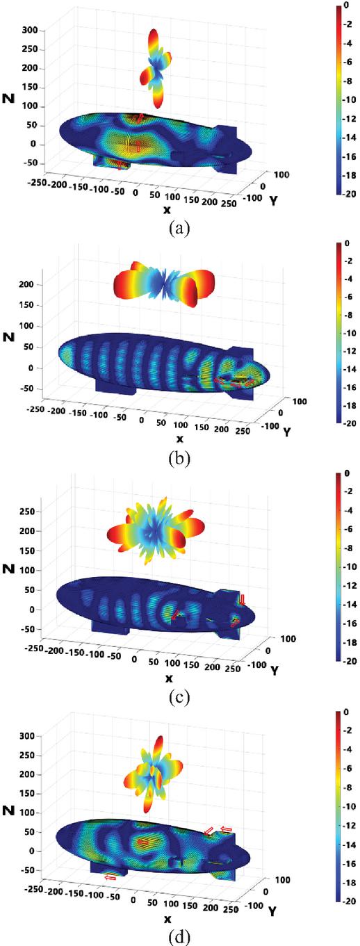
Figure 2: Normalized characteristic fields and currents of the airship at 4 GHz (units: dB). (a) 1st mode. (b) 11th mode. (c) 31th mode. (d) 61th mode.
II. RADIATION PATTERN SYNTHESIS
We aim to streamline analysis of the airship in communication systems, focusing on a distributed heterogeneous array design. Treating the airship as a fully metallic body based on electromagnetic theory, we propose an antenna for a simplified model with dimensions of 20.68.3845.68 m (LWH), as illustrated in Fig. 1. To meet remote detection requirements, we design a conformal array with high gain at 100 MHz. In specific scenarios, the array must generate a horizontally polarized switchable beam within a designated range of the XOY plane. For practical experimental verification, we reduce the airship model to a 1:40 scale, and the working frequency is adjusted to 4 GHz.
A. Characteristic modes of the airship
For any metal conductor, distinct CM currents exist on its surface, and their distribution is an intrinsic property of the conductor [14, 15]. These CMs are independent of the excitation source and are solely determined by the shape, size, and materials of the electromagnetic structure. This independence offers a clear physical basis for investigating the inherent radiation mechanism.
It should be noted that in equation (1), R and X denote the symmetric and antisymmetric parts of the impedance matrix Z, rather than its strict real and imaginary components. This definition follows the classical Hermitian decomposition of the impedance operator proposed by Harrington and Mautz and later applied to microstrip structures by Angiulli et al. [16].
First, we decompose the impedance matrix Z into a combination of Hermitian real and imaginary parts:
| (1) |
Among them are:
| (2) | ||
| (3) |
If the impedance matrix Z is symmetric, then both R and X are real symmetric matrices, and R is positive semidefinite. Consider the following weighted eigenvalue equation:
| (4) |
where is the eigenvector, is the eigenvalue, and W is a constructed matrix that diagonalizes the impedance matrix Z on the left. It is easy to see that as long as W is a symmetric matrix, the requirement is met. However, to ensure orthogonality in the far field of the mode, and is chosen. Substituting into equation (4) get equation (5). The CMs of a perfectly electrically conducting (PEC) body can be determined through a generalized eigenvalue equation [17]:
| (5) |
Here and are characteristic current and eigenvalue of the nth CM, n is the index of the order, and R and X are the real and imaginary parts of a method of moment (MoM) impedance matrix calculated for the electric field integral equation (EFIF) [18].
Figure 2 displays normalized characteristic electric field and characteristic current distribution diagrams for four randomly chosen significant modes (mode 1, mode 11, mode 31, and mode 61) out of the 90 identified modes. In mode 1, dominant currents spread in four directions along both sides of the pod and the airship gasbag. Mode 11 exhibits maximum transverse currents along the three edges of the two tail fins. Mode 31 resonates along the edges of the tail and the propulsion unit. Mode 61’s maximum current is distributed across multiple structures.
To ensure that only physically meaningful modes contribute to pattern synthesis, a quantitative criterion was used to define “significant” modes. The modal significance (MS) is expressed as:
| (6) |
where is the eigenvalue of the th mode. Modes with and radiation efficiency exceeding 80% were selected as significant modes. In total, 90 modes were calculated, from which four representative significant modes (1st, 11th, 31st, and 61st) were extracted for optimization and synthesis. This formal selection criterion aligns with the classical CM theory proposed by Harrington and Mautz [18], ensuring both physical interpretability and numerical robustness of the optimization process.
For exciting a specific mode, a suitable current excitation should align with the characteristic current distribution. Modes 1 and 11 have radiation patterns with four beams of nearly equal amplitude, but their distribution planes differ (XOZ for mode 1 and XOY for mode 11). The lobes of modes 31 and 11 are relatively close, and the maximum radiation direction of mode 61 is also close to that of mode 1. However, these higher-order modes exhibit high sidelobe levels (SLL), as predicted from their current distributions. The selected modes are representative, and other significant modes lack scanning beams in their characteristic electric fields. Although a single mode is insufficient, their characteristic fields provide sufficient degrees of freedom for scanning pattern synthesis.
Table 1: Modal significance for a metal platform’s first four modes. Mode 1 resonates at 4 GHz, with no other significant modes at this frequency
| Mode No. | 1 | 2 | 3 | 4 | 5 |
| MS | 0.898951 | 0.294527 | 0.189356 | 0.136325 | 0.0504503 |
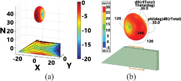
Figure 3: (a) Characteristic electric field and characteristic current of the significant mode of a metal platform. (b) Schematic diagram of significant mode and electric field of metal platform excited by half loop antenna.
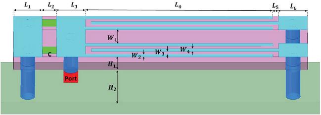
Figure 4: Top view of couple-line CE integrated on the platform.
B. Radiation pattern synthesis
Conventionally, the cost function of the multi-objective optimization algorithm is set according to the parameters of desired radiation patterns. In this design, to optimize the beam direction and the energy distributions, the following three cost functions are set:
| (7) | |
| (8) | |
| (9) |
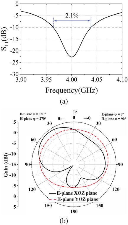
Figure 5: Couple-line CE: (a) reflection coefficient and (b) radiation pattern.
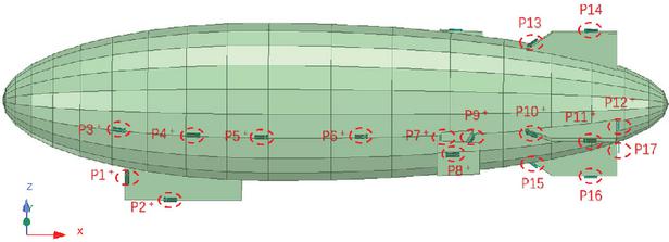
Figure 6: Excitation locations over the airship platform.
CM analysis and modal impedance extraction were conducted using an in-house C++ MoM solver compiled with Code::Blocks (MinGW64), following the workflow described in the program instruction manual, where the HFSS-derived mesh model (.nas) was imported and solved in Release mode for improved numerical stability. The subsequent beam synthesis optimization employed a C++ implementation of the MOEA/D multi-objective differential evolution algorithm, targeting main-lobe steering accuracy, polarization purity, and sidelobe suppression, while post-processing and visualization were performed in MATLAB. Each optimization run included 300 generations with about 178500 fitness evaluations, executed on a workstation equipped with an 11th Gen Intel Core i7-1165G7 CPU (2.80 GHz, 4 cores), 16 GB RAM, and Intel Iris Xe Graphics, requiring a total runtime of approximately 57574 s (16 h). This configuration confirms that the proposed CM-MOEA/D closed-loop framework can be efficiently implemented on a standard PC.
Based on the cost function established by the MOEA/D, the characteristic field and current component obtained from the CM analysis platform can be utilized to solve at the current scanning angle. Subsequently, the solver produces a set of Pareto-optimal solutions for the synthesized field and current solution.
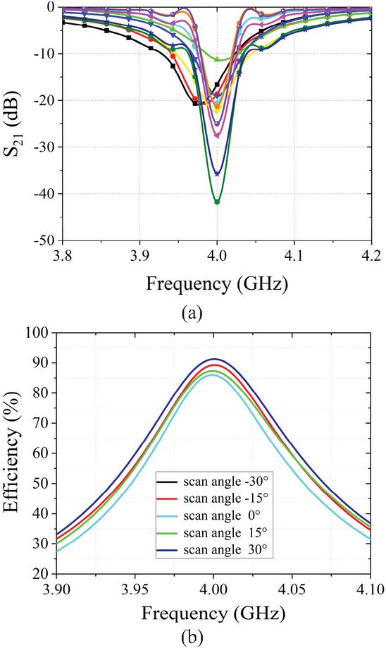
Figure 8: (a) S21 in the array environment active reflection coefficient at scan angle of 0∘. (b) Radiation efficiency of antenna array at different scan angles.
III. DISTRIBUTED HETEROGENEOUS CONFORMAL ARRAY DEVELOPMENT
This paper focuses on the current distribution of the synthesized mode as the main basis for designing a distributed heterogeneous conformal array for an airship platform. The design and arrangement of CEs will be based on this distribution, and MOEA/D will be used to obtain the normalized excitation amplitude and phase of multiple CEs at various scan angles. This section also presents the measured results.
A. Coupling elements design
The excitation structure can stimulate single mode or synthesized mode current using electric field or magnetic field induction methods. The metal platform, based on the airship is tail structure, demonstrates this. Figure 3 (a) shows characteristic fields and currents for the platform’s dominant mode at 4 GHz, with currents mainly along the platform’s longest edges. In Fig. 3 (b), a half-ring antenna is positioned vertically along the platform’s long edge, with a 0.066 pF capacitor at the port. The electric field excited by inductive coupled element (ICE)aligns well with the characteristic electric field. It is also important to mention that the CM isn’t linked to the external excitation source. Thus, CEs don’t need to be included in the airship is CM analysis. However, the CEs’ physical size should be minimized to avoid a significant impact on the characteristic value and electric field of the airship.
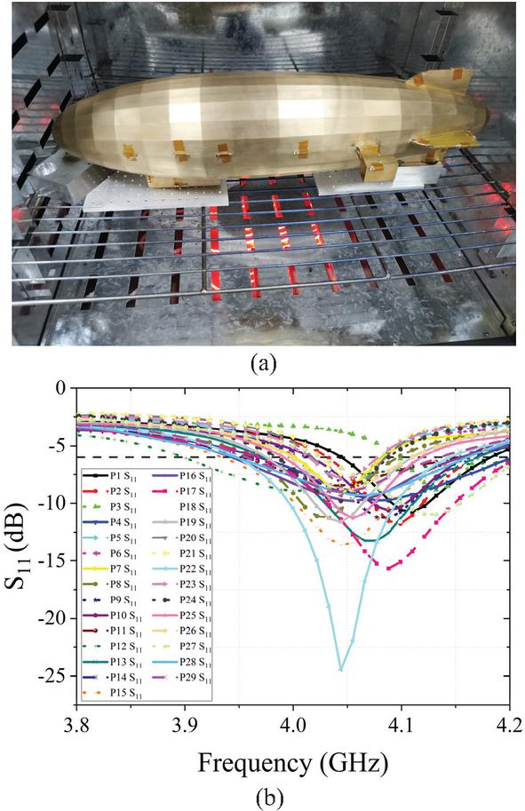
Figure 9: (a) Prototype of the fabricated antenna array. (b) Measured reflection coefficient.
Table 2: Performances comparison for proposed airship-based CM-MOEA/D framework with existing CM-based designs, showing a wider 60∘ continuous scanning range, lower sidelobes, and improved polarization control compared with prior VHF and side
| Ref. | Operating Band | Number of | Beam Scanning | Radiation | Sidelobe |
| Effective Modes | Range | Efficiency | Level (SLL) | ||
| [19] | VHF band (118–137 MHz) | 3–4 dominant modes | 45∘ discrete beams | 75–80 % (main beam) | 10 dB typical |
| [20] | 2.4 GHz WLAN band | 2 magnetic modes | Fixed broadside dual-pol radiation | 70–78 % | 15 dB (E/H planes) |
| This Work | Meter-wave (100 MHz, scaled to 4 GHz model) | 12 dominant modes | 60∘ continuous scan with stable gain | 85 % (full scan) | 13 dB across scan |
The airship platform structure, including the airbag, must ensure continuity. Embedded schemes are avoided in the design of CEs, and conformal requirements are met through low profile and electrically small size. The interdigital coupling line’s deformation structure is based on the classical half-ring CE, as shown in Fig. 4. A lumped capacitor of C 0.6 pF is added to the structure for impedance matching, with a dielectric plate of . Figure 5 depicts the reflection coefficient and radiation pattern of the coupled line CE, with a maximum realized gain of 4.2 dBi. The distributed inductance, created by deforming part of the half-ring radiator into an interdigital coupling line, has a tuning effect on the CE. Additionally, the coupled line CE includes two deformation structures that simultaneously stimulate the CM of the platform, thereby enhancing the bandwidth to a certain extent.
Compared with modal synthesis results in [19], where four dominant aircraft modes produced discrete 45∘ scanning with 9 dB SLL, the present design utilizes 12 significant modes to realize continuous 60∘ beam scanning and SLL below 13 dB. This indicates that the proposed CM-MOEA/D framework approaches the modal-limited directivity bound while balancing beamwidth and side.
In this paper, a scaled prototype was employed, the operating frequency was proportionally scaled, maintaining the same electrical size and equivalent number of effective CEs as in a full-scale airship. This approach, also adopted in [21], ensures electromagnetic equivalence while facilitating laboratory measurement. The proposed array is fully conformal with the airship body, where the CEs function as distributed excitation structures rather than protruding antennas, avoiding added aerodynamic and structural loads. For large apertures, modular subarray optimization can be applied within the same CM-MOEA/D framework, ensuring scalability and practical feasibility.
B. Distributed heterogeneous phased array design
The CEs (P18 to P29) are positioned as shown in Fig. 6. The beam scans in the negative Y-axis direction and transforms into symmetric excitation to obtain the scanning beam on the other side. Fine-tuning the CE size and patch capacitance is necessary to match the input port impedance.
This paper proposes a method to determine excitation amplitude and phase of CEs at different scan angles. It involves: (a) adjusting excitation amplitude based on current distribution; (b) conducting full-wave simulation on the airship platform; (c) using MOEA/D based on far-field information to solve for excitation amplitude and phase. The excitation power of CEs is discretized, and the optimized excitation amplitudes for the radiation beams are shown in Fig. 7. Additionally, some CEs will have small amplitudes of excitation to optimize side lobe and cross-polarization level. The array S21 is depicted in Figs. 8 (a) and 8 (b), the radiation efficiency exceeds 80% at different scan angles near the working frequency, enhancing the platform’s radiation efficiency and increasing the radiation aperture compared to traditional meter-wave antennas.
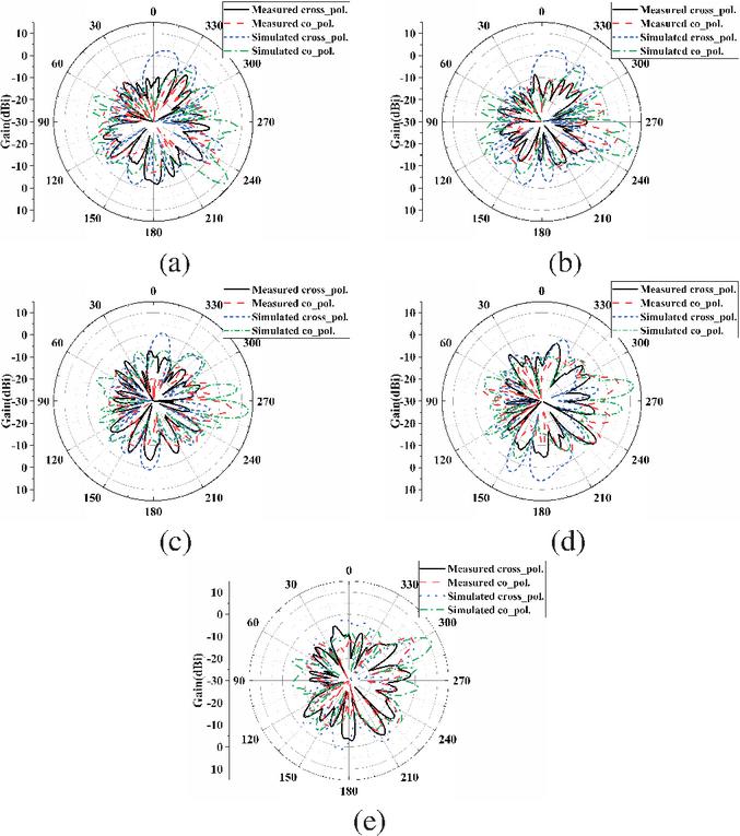
Figure 10: Simulated and measured radiation patterns in the E-plane (XOY plane) at 4 GH. (a) Beam steered [], (b) beam steered [], (c) broadside [], (d) beam steered [], (e) beam steered [].
C. Antenna performance
The scale airship platform and CEs were fabricated. The length of the platform is 515 mm, and the material is brass for easy welding. As for the coupling line CE, it is difficult for the short-circuit column to weld and support the weight of the coaxial transmission line under the scaled size. The overall coupling line structure is not changed. A Taconic RF-35 dielectric plate with thickness 1.52 mm and is adopted. The short-circuit column is redesigned as a metallic via, allowing the entire bottom surface of the CE to be brought into contact with and mechanically fixed to the platform. In addition, since no lumped elements are employed, no extra matching network is required, thereby avoiding the associated tolerance and mismatch errors.
Figure 9 (a) displays the fabricated prototype of the distributed heterogeneous phased array system. Figure 9 (b) illustrates the measured reflection coefficient of the array. Despite machining errors in the platform and CEs, deviation in the fixed position of the CEs, and error amplification during scaling, the reflection coefficient experiences a certain degree of deterioration and frequency deviation. Nevertheless, with the exception of a few CEs, the reflection coefficient satisfies the requirement of being less than 6 dB near 4.06 GHz. As a result, the simulated and measured radiation patterns in the E-plane (XOY plane) at 4 GHz is shown in Fig. 10. To facilitate easy coaxial line fixation and minimize radiation impact with small unit spacing, we adopted a thin coaxial line with an outer diameter of 0.9 mm, which results in relatively large insertion losses. Furthermore, the CEs’ reflection coefficient displays varying degrees of frequency deviation, and installation position and platform structure errors lead to a decrease in measured gain. However, the beam direction at various scan angles correspond well with the simulation results and has low levels of cross-polarization and sidelobes.
The airship-based conformal array is designed with system-level integration in mind. The low-profile structure conforms to the curved envelope, effectively minimizing aerodynamic drag and payload protrusion. The number of active modes is determined using the modal significance threshold (MS 0.707), ensuring efficient excitation without unnecessary modal expansion. This constraint not only reduces structural and computational complexity but also maintains stable directivity and low sidelobe levels. Furthermore, the smooth surface integration helps reduce RCS and improve stealth compatibility for high-altitude platforms.
IV. CONCLUSION
This paper outlines a CM-based approach for designing a distributed heterogeneous conformal phased array system. It considers polarization characteristics and beam switchable ability for specific communication requirements. This guides the placement of the designed coupling line CEs. The system achieves a 60∘ beam scanning range on both sides of the airship platform, with a gain of over 10 dBi at different scan angles. A 1:40 scale model was fabricated and measured to validate the design method. This approach can be applied to the design of conformal phased array antennas on other platforms.
ACKNOWLEDGMENT
This work was supported in part by the Postdoctoral Innovative Talent Support Program (Boshi Plan) of China under Grant No. GZB20250133, National Natural Science Foundation of China (No. 62531021) and in part by the Open Fund of the State Key Laboratory of Millimeter Waves, Southeast University under Grant KN202502-01.
REFERENCES
[1] L. V. Berkner, “Naval airborne radar,” Proceedings of the IRE, vol. 34, pp. 671–706, Sep. 1946.
[2] F. W. Cipola, “A 7.5-GHz microstrip phased array for aircraft-to-satellite communication,” IEEE Trans. Antennas Propag., vol. 29, no. 1, pp. 166–170, Jan. 1981.
[3] Z. Li, K. Wang, Y. Lv, S. Qian, X. Zhang, and X. Cui, “Wing conformal load-bearing endfire phased array antenna skin technology,” IEEE Trans. Antennas Propag., vol. 71, no. 3, pp. 2064–2069, Mar. 2023.
[4] J.-J. Peng, S.-W. Qu, M. Xia, and S. Yang, “Conformal phased array antenna for unmanned aerial vehicle with 70∘ scanning range,” IEEE Trans. Antennas Propag., vol. 69, no. 8, pp. 4580–4587, Aug. 2021.
[5] W. F. Bahret, “The beginnings of stealth technology,” IEEE Transactions on Aerospace and Electronic Systems, vol. 29, no. 4, pp. 1377–1385, Oct. 1993.
[6] V. Manohar, S. Bhardwaj, S. B. Venkatakrishnan, and J. L. Volakis, “VHF/UHF ultrawideband tightly coupled dipole array for CubeSats,” IEEE Open J. Antennas Propag., vol. 2, pp. 702–708, 2021.
[7] J. D. Hawkins, L. B. Lok, P. V. Brennan, and K. W. Nicholls, “HF wiremesh dipole antennas for broadband ice-penetrating radar,” IEEE Antennas Wireless Propag. Lett., vol. 19, no. 12, pp. 2172–2176, Dec. 2020.
[8] Y. Gao, D. Wu, and Q. Wu, “Analysis of conformal antenna arrays using cylindrical periodic Green’s function and RWG basis function,” IEEE Trans. Antennas Propag., vol. 72, no. 2, pp. 1385–1396, Feb. 2024.
[9] Y. Chen and C. F. Wang, “HF band shipboard antenna design using characteristic modes,” IEEE Trans. Antennas Propag., vol. 63, no. 3, pp. 1004–1013, Mar. 2015.
[10] Y. Chen and C.-F. Wang, “Electrically small UAV antenna design using characteristic modes,” IEEE Trans. Antennas Propag., vol. 62, no. 2, pp. 535–545, Feb. 2014.
[11] C. Wang, Y. Chen, and S. Yang, “Application of characteristic mode theory in HF band aircraft-integrated multiantenna system designs,” IEEE Trans. Antennas Propag., vol. 67, no. 1, pp. 513–521, Jan. 2019.
[12] R. F. M. Delgado Castillo, R. Ma, and N. Behdad, “Platform-based, electrically-small HF antenna with switchable directional radiation patterns,” IEEE Trans. Antennas Propag., vol. 69, no. 8, pp. 4370–4379, Aug. 2021.
[13] K. Ren, M. Ranjbar Nikkhah, and N. Behdad, “Design of dual polarized platform-based HF antennas using the characteristic mode theory,” IEEE Trans. Antennas Propag., vol. 68, no. 7, pp. 5130–5141, Feb. 2020.
[14] R. Ma and N. Behdad, “Design of platform-based HF direction-finding antennas using the characteristic mode theory,” IEEE Trans. Antennas Propag., vol. 67, no. 3, pp. 1417–1427, Mar. 2019.
[15] C. Wang, Y. Chen, G. Liu, and S. Yang, “Aircraft-integrated VHF band antenna array designs using characteristic modes,” IEEE Trans. Antennas Propag., vol. 68, no. 11, pp. 7358–7369, Nov. 2020.
[16] G. Angiulli, G. Amendola, and G. Di Massa, “Application of characteristic modes to the analysis of scattering from microstrip antennas,” Journal of Electromagnetic Waves and Applications, vol. 14, no. 8, pp. 1063–1081, 2000.
[17] R. J. Garbacz and R. H. Turpin, “A generalized expansion for radiated and scattered fields,” IEEE Trans. Antennas Propag., vol. 19, no. 3, pp. 348–358, May 1971.
[18] R. Harrington and J. Mautz, “Theory of characteristic modes for conducting bodies,” IEEE Trans. Antennas Propag., vol. 19, no. 5, pp. 622–628, Sep. 1971.
[19] C. Wang, Y. Chen, G. Liu, and S. Yang, “Aircraft-integrated VHF band antenna array designs using characteristic modes,” IEEE Trans. Antennas Propag., vol. 68, no. 11, pp. 7358–7369, Nov. 2020.
[20] C. Wang, Y. Chen, and S. Yang, “Bandwidth enhancement of a dual-polarized slot antenna using characteristic modes,” IEEE Antennas Wireless Propag. Lett., vol. 17, no. 6, pp. 988–992, June 2018.
[21] C. Wang, Y. Chen, and S. Yang, “Application of characteristic mode theory in HF band aircraft-integrated multiantenna system designs,” IEEE Trans. Antennas Propag., vol. 67, no. 1, pp. 513–521, Jan. 2019.
BIOGRAPHIES

Yuhao Feng received the B.S. degree in information science and technology from the University of Arizona, Tucson, AZ, USA, in 2018, the M.S. degree in electronic engineering from the Colorado School of Mines, Golden, CO, in 2020, and the Ph.D. degree in electronic science and technology from the University of Electronic Science and Technology of China (UESTC), Chengdu, China, in 2024. His research interests include antennas, filters, and RF circuits.

Zijian Yang received the M.S. degree in electronic science and technology from the University of Electronic Science and Technology of China (UESTC), Chengdu, China, in 2022, and is currently an RF antenna engineer with Shenzhen.
ACES JOURNAL, Vol. 40, No. 11, 1064–1072
DOI: 10.13052/2025.ACES.J.401102
© 2025 River Publishers