Three-Port Common Aperture Metasurface Antenna Designed Using Characteristic Mode Analysis
Z. N. Jiang1, 2, L. Wu1, B. Z. Sun1, and L. L. Yu1
1School of Computer and Information Hefei University of Technology, Hefei, China
jiangzhaoneng@hfut.edu.cn, 2916956457@qq.com, 2909503223@qq.com, yll@hfut.edu.cn
2National Mobile Communications Research Laboratory Southeast University, Jiangsu, China
Submitted On: September 03, 2025 Accepted On: July 07, 2026
ABSTRACT
In this paper, a three-port common aperture antenna based on metasurface (MTS) is presented. The omnidirectional radiation pattern of the two frequency bands is excited through the coupling of the central coaxial cable and the slit feed, respectively. The annular microstrip structure is introduced into the multi-layer structure design to generate wide-beam radiation along the Z-axis. Characteristic modal analysis (CMA) is used to adjust the shape and size of the MTS patch to increase the bandwidth of the omnidirectional mode. The optimized antenna size is . Simulation and measurement results show that the omnidirectional radiation characteristics can be realized in dual-band impedance bandwidths of 2.92–3.08 GHz and 4.11–4.69 GHz, respectively. In the 1.74–1.87 GHz band, the half-power beamwidth (HPBW) of the E and H planes is at least 100∘ and 80∘, respectively. The antenna achieves the performance of multi-band and wide-angle radiation while saving space volume as much as possible.
Keywords: CMA, metasurface (MTS), omnidirectional, three-port, wide-beam..
1 INTRODUCTION
With the continuous development of wireless communication technology in various communication applications, common aperture antennas have been widely concerned because of their multi-function integration, such as multi-frequency band and multi-radiation direction, which can effectively reduce the cost and volume of the system. At present, common-aperture antennas are widely used in military, commercial, and medical fields [1, 2, 3, 4, 5, 6], also synthetic aperture radar [2], low Earth orbit satellites [3, 4], and mobile communications [5].
Metasurface (MTS) can increase bandwidth and reduce antenna size [7, 8, 9, 10], and is often viewed as a 2D metamaterial [11]. In [12], the three modes of the MTS are combined with the mode of the slot to achieve an impedance bandwidth of more than 79% under multi-mode resonance. The MTS antenna in [13] is miniaturized by reducing the side gap and expanding the center gap to achieve good bandwidth. In [14], wideband impedance matching is achieved by loading non-uniform MTS onto a stair-shape aperture.
Characteristic modal analysis (CMA) is a suitable antenna design method that mainly analyzes the radiation behavior of the antenna from a physical perspective by studying the current distribution of the characteristic mode [15, 16]. In particular, there are some examples based on CMA in the optimized design of MTS structures. In [17], a method is proposed for designing an anisotropic complementary metantenna that combines low sidelobe levels and low in-band co-polarized scattering for wide-side radiation. An example is provided in reference [18] of loading a square MTS cell array to help the antenna achieve dual-band operation, where four cells are cut at the corners to suppress unwanted patterns.
In this paper, a three-port share-aperture antenna based on MTS is designed by using the merit adaptability of the share-aperture structure to the scarce space resources and the complex space structure, and by using the CMA. Two radiation effects of omnidirectional radiation and wide-beam radiation are realized by feeding excitation at different positions of the upper microstrip patch. Simulation and measurement results show that the proposed three-port common aperture antenna achieves an omnidirectional radiation effect in the dual-band impedance bandwidths of 2.92–3.08 GHz and 4.1–4.69 GHz, respectively, and a wide-beam radiation effect in the band of 1.74–1.87 GHz.
2 ANTENNA DESIGN AND ANALYSIS
2.1 Steps of antenna design and analysis
In wide-beam antenna design, 3-dB beamwidth is critical. A 360∘ beamwidth on a plane defines an omnidirectional antenna. For MTS-based antennas, a rectangular MTS with central capacitive coupling excitation (CCE) is commonly used for omnidirectional radiation. However, the CCE structure introduces a deviation in the resonant frequency predicted by characteristic mode theory by altering the field distribution on the microstrip patch. To systematically address this issue, CMA is adopted here as a design tool. CMA provides a physical basis for selecting modes that are close to resonance and exhibit desired radiation patterns. By comparing rectangular and circular MTS layouts (Fig. 1), modes with omnidirectional or wide-beam potential are identified based on their characteristic currents and 3D patterns. The following subsections detail the CMA-guided design process.
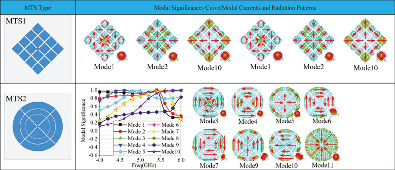
Figure 1 rectangular MTS (MTS1), circular MTS (MTS2), and the MS curve, modal currents, and radiation patterns of MTS1 and MTS2.
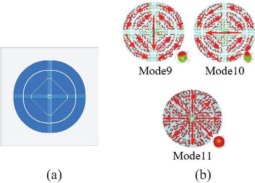
Figure 2 (a) Optimized circular MTS. (b) Current distribution and radiation patterns of optimized MTS at 4 GHz.
Figure 1 shows the rectangular MTS (MTS1) and circular MTS (MTS2) structures with their modal significance (MS) curves, where MS indicates how close a mode is to resonance (MS 1 for ideal resonance). The mode currents and radiation patterns for MTS1 and MTS2 are also presented. The modal solutions of the MTS structures are analyzed using CST. The MS curve of MTS1 shows good matching potential in the 4–6 GHz band. Modes 1, 2, and 10 with potential omnidirectional radiation potential are selected. However, considering the limitations of the antenna feed structure, the current distribution should be in a state of uniform divergence around to form a good vertical polarization characteristic. Mode 10 conforming to the feed structure is selected, but its antenna pattern roundness on the E plane is higher than 4 dB, and the radiation beamwidth on the H plane still needs to be further optimized.
To improve the omnidirectional pattern roundness, the rectangular MTS is replaced by a circular one (MTS2 in Fig. 1). Modes with modal significance MS 0.5 (meaning the mode is sufficiently close to resonance and can be effectively excited) and regular 3D patterns are displayed to analyze the required radiation modes. Eight modes are thus selected.
Modes 3, 4, 5, and 11 of MTS2 all have the potential of omnidirectional radiation. By analyzing the surface current, mode 11 is selected as the omnidirectional radiation mode. In addition, although modes 9 and 10 do not have omnidirectional radiation characteristics, they have broad beam radiation characteristics along the X- and Y-axis. The current distribution of mode 9 and mode 10 is basically the same, except that mode 9 is polarized along the X -axis and mode 10 is polarized along the Y-axis, so mode 9 and mode 10 are a pair of merging modes. In the two modes, the feed position of capacitive coupling excitation is inconsistent with that of omnidirectional radiation excitation, so a circular microstrip patch can be used to stimulate dual-polarized radiation to achieve a wide-beam common aperture structure design. At the same time, the capacitive patch structure directly connected with the inner conductor of the coaxial line was optimized, and the final microstrip patch structure design is shown in Fig. 2 (a). The surface current distribution of optimized modes 11, 9, and 10 at 4 GHz is shown in Fig. 2 (b). In addition, considering that the antenna has the potential of multi-layer structure design, the annular rectangular microstrip structure is introduced, so the antenna can achieve wide-beam radiation. At the same time, the coupled feed is used to excite the omnidirectional radiation in another frequency band of the MTS. To increase the isolation from the central coaxial line, the H-shaped coupling groove is etched in the corresponding coupling position in the ground layer. In addition, by etching four circular grooves in the ground layer and changing the electromagnetic field structure between the top radiation patch and the ground, the omnidirectional radiation irregularity can be optimized.
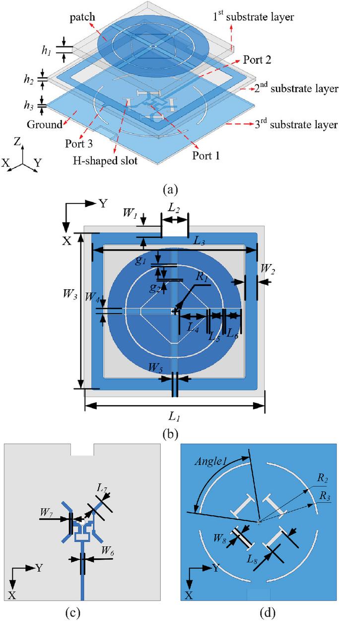
Figure 3 Structure view of the proposed three-port common aperture antenna. (a) 3D view, (b) top view, (c) bottom view, and (d) ground layer.
2.2 Antenna model
Based on the above analysis, a three-port common aperture antenna is proposed. The antenna structure diagram is shown in Fig. 3. The 1st and 2nd substrate layers of the antenna are composed of FR4 ( and ). MTS and ring patches are printed on the 1st and the 2nd substrate layers, respectively, to generate omnidirectional and wide-beam radiation. The metal microstrips on both sides of the 3rd substrate layer (Rogers5880 with and ) constitute the ground and feed structure, respectively. The ground has four H-shaped slots and four arc-shaped slots etched on it. On the reverse side of the feeding layer, a hybrid Wilkinson T-type power divider is adopted to uniformly excite the metasurface, which guarantees identical phase responses across all antenna ports and realizes a 1-to-4 power division function.
The dimensions of the antenna are shown in Table 1.
Table 1 Dimensions of the proposed three-port antenna (units: mm)
| Symbol | Value | Symbol | Value | Symbol | Value |
| 80 | 12 | 73 | |||
| 13 | 6 | 7.6 | |||
| 6 | 5 | 5.5 | |||
| 73.2 | 2.6 | 2 | |||
| 1.58 | 0.46 | 2 | |||
| 11 | 0.8 | 0.6 | |||
| 0.5 | 31 | 30 | |||
| 4 | 2 | 1 | |||
| Angle |
3 EXPERIMENTAL RESULTS
The fabricated prototypes of the three-port antenna are shown in Fig. 4. The simulation is conducted using HFSS. Figure 5 depicts the simulated and measured normalized radiation patterns of the antenna. The antenna achieves omnidirectional radiation beams of less than 2 dB pattern roundness and 100∘ wide-beam radiation, and the difference between the main and cross polarization is greater than 10 dB. The measured and simulated S-parameters of each port are shown in Fig. 6. The peak gain curve of each port is shown in Fig. 7 (a), and the simulation efficiency is shown in Fig. 7 (b). For omnidirectional mode, and bandwidths of 5.3% (2.92–3.08 GHz) and 13.2% (4.11–4.69 GHz), respectively. The simulation efficiency of in-band radiation is higher than 60% and 80%, respectively. For wide-beam radiation mode, the bandwidth is 7.2% (1.74–1.87 GHz). In-band simulation radiation efficiency is higher than 60%. The isolation between any two ports is higher than 22 dB, indicating low mutual coupling and sufficient port independence for multi-port operation.
The simulation and measurement curves are generally consistent, showing that the designed three-port common aperture antenna meets the expected radiation performance. The discrepancy between simulated and measured results is mainly attributed to welding errors, substrate gaps, and measurement environmental errors.
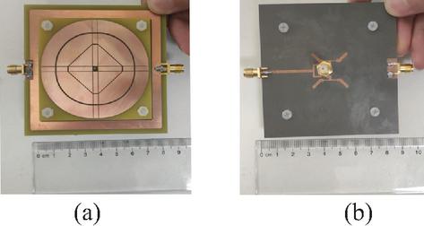
Figure 4 Photographs of the fabricated three-port antenna. (a) Front view and (b) back view.
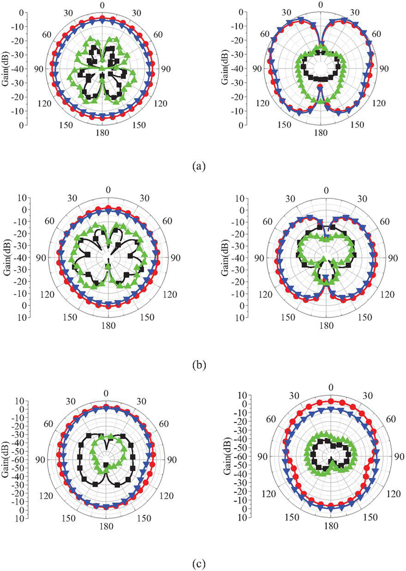
Figure 5 Measured directional pattern of the proposed three-port antenna E plane (left) and H plane (right). (a) Radiation pattern of port 1 at 3 GHz, (b) radiation pattern of port 2 at 4.3 GHz, and (c) radiation pattern of port 3 at 1.8 GHz.
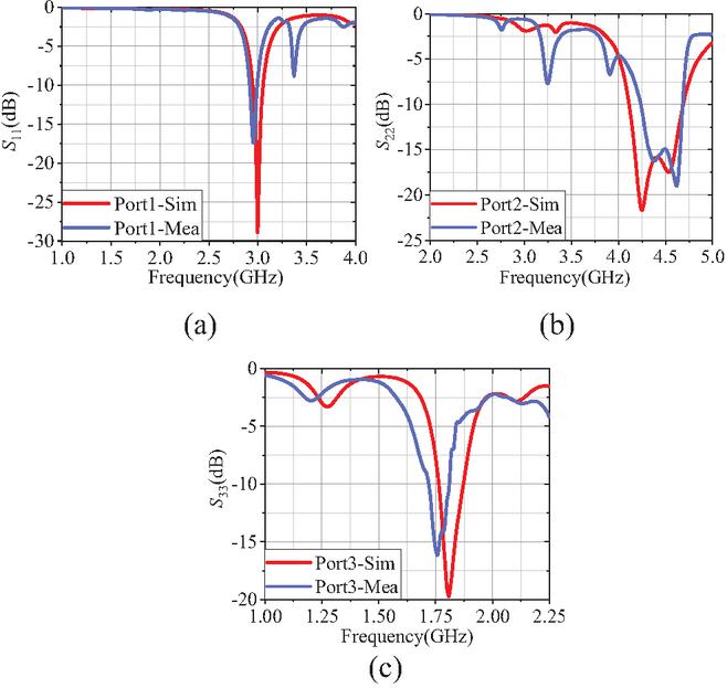
Figure 6 Measured and simulated S-parameters of the proposed three-port antenna. (a) Port 1, (b) port 2, and (c) port 3.
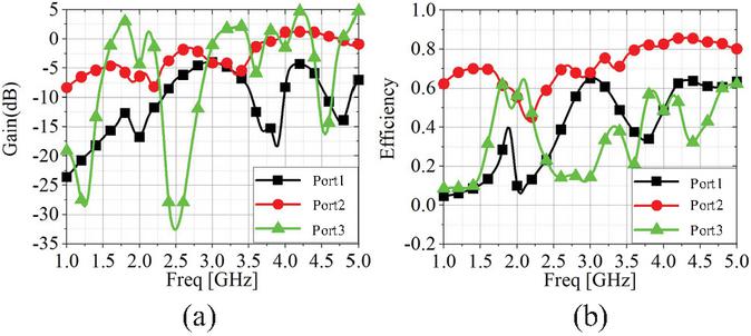
Figure 7 (a) Peak gain curve of the proposed three-port antenna. (b) Radiation efficiency curve of the proposed three-port antenna.
Table 2 Comparison with other three-port antennas
| Ref. | Basic Structure | Working Frequency (GHz) | Size | Iso. (dB) |
| [6] | Slot structure; Rectangular loop | 0.77–0.93 | 19 | |
| 1.53–1.83 | ||||
| 2.4–2.64 | ||||
| [9] | MTS | 3.26–3.84 | 22 | |
| [19] | Dielectric resonator antenna | 5.58–6.17 | 17 | |
| [20] | Dipoles, loop arrays | 3.5–5.4 | 22 | |
| [21] | Single patch | 3.3–3.68 | 35 | |
| [22] | Circular and ring patches | 2.98–4.75 | 15.3 | |
| Proposed | MTS | 1.74–1.87 | 22 | |
| 2.92–3.08 | ||||
| 4.1–4.69 |
Table 2 compares the proposed antenna with existing three-port antennas in bandwidth, size, and isolation. Unlike [9, 19, 20, 21, 22] in single continuous bands, the proposed antenna has different radiation patterns across its three bands. Its isolation is better than [19, 22], comparable to [9, 20], and worse than [21]. Its profile is lower than [20, 22]. Compared with [6], it provides band-specific patterns and higher isolation.
4 CONCLUSION
In this work, a three-port common aperture antenna based on MTS is designed and fabricated. The power divider coupling feed stimulates omnidirectional radiation performance at high frequency by feeding at different positions of the circular microstrip structure. At the same time, an annular microstrip patch structure is introduced in different outer layers of the MTS so that the antenna can generate wide-beam radiation. The antenna can generate omnidirectional radiation in the 2.92–3.08 GHz low frequency band and 4.11–4.69 GHz high frequency band, respectively, and wide-beam radiation in the 1.74–1.87 GHz low frequency band. The antenna presented in this paper has dual-frequency omnidirectional radiation and low-frequency wide-beam radiation. The antenna achieves high isolation between any two ports while maintaining high radiation efficiency within the operating bands. The antenna design scheme can be used for reference when scarce space resources and antenna integration requirements are high.
ACKNOWLEDGMENT
This work was supported by fund of Anhui Natural Science Foundation (No. 2208085MF161, No. 2208085QF185), Hefei Municipal Natural Science Foundation under Grant HZR2403, the Fundamental Research Funds (W2025JSKF0089, W2024JSKF0854).
REFERENCES
[1] B. Yang, Y. Xu, J. Tong, Y. Zhang, Y. Feng, and Y. Hu, “Tri-port antenna with shared radiator and self-decoupling characteristic for 5G smartphone application,” IEEE Trans. Antennas Propag., vol. 70, no. 6, pp. 4836–4841, June 2022.
[2] F. Qin, S. Gao, Q. Luo, C. X. Mao, C. Gu, G. Wei, J. Xu, J. Li, C. Wu, K. Zheng, and S. Zheng, “A simple low-cost common aperture dual-band dual-polarized high-gain antenna for synthetic aperture radars,” IEEE Trans. Antennas Propag., vol. 64, no. 7, pp. 2914–2922, July 2016.
[3] J. Ran, Y. Wu, C. Jin, P. Zhang, and W. Wang, “Dual-band multipolarized aperture-shared antenna array for Ku-/Ka-band satellite communication,” IEEE Trans. Antennas Propag., vol. 71, no. 5, pp. 3882–3893, May 2023.
[4] X. Li, R. Ma, H. Cai, Y.-M. Pan, and X. Y. Zhang, “High-gain dual-band aperture-shared CP patch antenna with wide AR beamwidth for satellite navigation system,” IEEE Antennas Wireless Propag. Lett., vol. 22, no. 8, pp. 1888–1891, Aug. 2023.
[5] Z. Wang, Y. Ning, and Y. Dong, “Hybrid metamaterial-TL-based, low-profile, dual-polarized omnidirectional antenna for 5G indoor application,” IEEE Trans. Antennas Propag., vol. 70, no. 4, pp. 2561–2570, Apr. 2022.
[6] P. Cheong, K.-F. Chang, W.-W. Choi, and K.-W. Tam, “A highly integrated antenna-triplexer with simultaneous three-port isolations based on multi-mode excitation,” IEEE Trans. Antennas Propag., vol. 63, no. 1, pp. 363–368, Jan. 2015.
[7] G. P. Gao, C. Yang, B. Hu, R. F. Zhang, and S. F. Wang, “A wearable PIFA with an all-textile MTS for 5 GHz WBAN applications,” IEEE Antennas Wireless Propag. Lett., vol. 18, no. 2, pp. 288–292, Feb. 2019.
[8] S. Liu, D. Yang, Y. Chen, K. Sun, X. Zhang, and Y. Xiang, “Low-profile broadband metasurface antenna under multimode resonance,” IEEE Antennas Wireless Propag. Lett., vol. 20, no. 9, pp. 1696–1700, Sep. 2021.
[9] Z. Wang, S. Liu, and Y. Dong, “Low-profile metasurface-based antenna with tripolarization for 5G applications,” IEEE Trans. Antennas Propag., vol. 69, no. 9, pp. 5437–5445, Sep. 2021.
[10] W. Yang, Q. Meng, W. Che, L. Gu, and Q. Xue, “Low-profile wideband dual-circularly polarized metasurface antenna array with large beamwidth,” IEEE Antennas Wireless Propag. Lett., vol. 17, no. 9, pp. 1613–1616, Sep. 2018.
[11] C. L. Holloway, E. F. Kuester, J. A. Gordon, J. O’Hara, J. Booth, and D. R. Smith, “An overview of the theory and applications of MTSs: The two-dimensional equivalents of metamaterials,” IEEE Antennas Propag. Mag., vol. 54, no. 2, pp. 10–35, Apr. 2012.
[12] S. Liu, D. Yang, Y. Chen, K. Sun, X. Zhang, and Y. Xiang, “Low-profile broadband metasurface antenna under multimode resonance,” IEEE Antennas Wireless Propag. Lett., vol. 20, no. 9, pp. 1696–1700, Sep. 2021.
[13] W. E. I. Liu, Z. N. Chen, and X. Qing, “Miniature wide-band non-uniform metasurface antenna using equivalent circuit model,” IEEE Trans. Antennas Propag., vol. 68, no. 7, pp. 5652–5657, July 2020.
[14] J. F. Wang, H. Wong, Z. Q. Ji, and Y. L. Wu, “Broadband CPW-fed aperture coupled MTS antenna,” IEEE Antennas Wireless Propag. Lett., vol. 18, no. 3, pp. 517–520, Mar. 2019.
[15] Z. Jiang, S. Meng, L. Nie, J. Qi, and F. Ji, “A low-profile tri-port multimode metasurface-based antenna using characteristic mode analysis,” IEEE Antennas Wireless Propag. Lett., vol. 24, no. 5, pp. 1119–1123, May 2025.
[16] G. Gao, R. F. Zhang, W. F. Geng, H. J. Meng, and B. Hu, “Characteristic mode analysis of a nonuniform metasurface antenna for wearable applications,” IEEE Antennas Wireless Propag. Lett., vol. 19, no. 8, pp. 1355–1359, Aug. 2020.
[17] Y.-H. Lv, R. Wang, B.-Z. Wang, and Z. N. Chen, “Anisotropic complementary metantenna for low sidelobe radiation and low in-band co-polarized scattering using characteristic mode analysis,” IEEE Trans. Antennas Propag., vol. 70, no. 11, pp. 10177–10186, Nov. 2022.
[18] T. Li and Z. N. Chen, “A dual-band MTS antenna using characteristic mode analysis,” IEEE Trans. Antennas Propag., vol. 66, no. 10, pp. 5620–5624, Oct. 2018.
[19] B. Zhang, J. Ren, T. Yang, Y.-T. Liu, Z. Zhao, and J. Zhao, “Three-port pattern- and polarization-diversity rectangular dielectric resonator antenna,” IEEE Trans. Antennas Propag., vol. 71, no. 6, pp. 5392–5397, June 2023.
[20] J. Han, R. Lian, D. Wu, M. Qin, and J. Zhang, “Design of a wideband tripolarized antenna with high isolation and diverse patterns,” IEEE Antennas Wireless Propag. Lett., vol. 23, no. 1, pp. 114–118, Jan. 2024.
[21] L. Y. Nie, B. K. Lau, H. Aliakbari, S. Xiang, B. Wang, and X. Q. Lin, “A low-profile wideband dual-resonance tri-port MIMO antenna,” IEEE Trans. Antennas Propag., vol. 70, no. 6, pp. 4866–4871, June 2022.
[22] Y. Yang, J. Ren, B. Zhang, J. Liu, H. Wang, and D. Song, “Wideband tripolarized MIMO antenna with pattern diversity for 5G application,” IEEE Antennas Wireless Propag. Lett., vol. 23, no. 1, pp. 349–353, Jan. 2024.
BIOGRAPHIES

Z. N. Jiang was born in Lianyungang, Jiangsu, China. He received the Ph.D. degree from Nangjing University of Science and Technology, Nanjing, in 2012. Since 2013, he has been engaged in research on numerical methods for computational electromagnetism. He is currently a Professor at Hefei University of Technology and a Distinguished Professor at Anhui Institute of Information Technology. He has authored or co-authored more than 100 papers in prestigious international journals and conferences, and has served as a Program Committee Member for several international conferences. His current research interests include antennas and microwave devices.

L. Wu, a native of Bozhou, Anhui Province, China, is currently pursuing the M.S. degree at Hefei University of Technology. He has been engaged in the research of microwave antenna design since 2024.

B. Z. Sun, a native of Huaibei, Anhui Province, China, is currently pursuing the M.S. degree at Hefei University of Technology. He has been engaged in the research of microwave antenna design since 2024.

L. L. Yu, native of Yuexi County, Anhui Province, China. He obtained his Master of Business Administration from the School of Management, Hefei University of Technology, in 2012. His professional endeavors focus on the management and research of information security and artificial intelligence applications. Currently, he serves as Deputy Director of the Office of Informationization Construction and Management at Hefei University of Technology. He is the author of several scholarly works, including Full-Stack Application and Migration of Domestic Operating Systems and Fundamentals and Applications of Artificial Intelligence. His current research interests encompass the integrated application of computer science and artificial intelligence technologies across diverse scenarios.
ACES JOURNAL, Vol. 41, No. 7, 614–620
DOI: 10.13052/2026.ACES.J.410702
© 2026 River Publishers