An Endfire Array Antenna for Simultaneous Operation in C- and X-Bands
Z. N. Jiang1, 2, W. X. Gao1, and C. Peng1
1School of Computer Science and Information
Hefei University of Technology, Hefei, China
jiangzhaoneng@hfut.edu.cn, 2970656281@qq.com, 3061596755@qq.com
2Anhui Institute of Information Technology
Wuhu, China
Submitted On: September 09, 2025; Accepted On: February 03, 2026
Abstract
In this paper, a broadband high-gain endfire array antenna based on spoof surface plasmon polaritons (SSPPs) is designed for simultaneous C- and X-band applications. To achieve endfire radiation, the SSPP structure is truncated to reduce its field confinement capability, while a radiating branch is loaded at the end of the transmission line to guide energy radiation. A rectangular metal ground is placed at the bottom of the antenna substrate to suppress backward radiation and optimize the contact area with the connector to ensure stable feeding. The final 14 endfire array antenna is formed by integrating unit antennas via a Wilkinson power divider-based feed network. A prototype was fabricated and tested, showing a 50% relative impedance bandwidth (6–10 GHz), 91% simulated radiation efficiency, 87% average measured radiation efficiency, and a maximum measured gain of 11.6 dBi at 9.7 GHz. With simple structure, low cost, and excellent performance, it is promising for C-band low-orbit satellite communication and X-band short-range radar.
Index Terms: Broadband, C-band, endfire array antenna, high gain, low-orbit satellite, short-range radar, Spoof Surface Plasmon Polaritons (SSPPs), X-band.
I. INTRODUCTION
At the metal-medium interface, free electrons interact with photons to form surface plasmon polaritons (SPPs), quasiparticles that characterize photon-electron coupling behavior [1, 2, 3]. SPPs propagate along the interface but decay rapidly in the direction perpendicular to it, exhibiting unique field confinement advantages in the optical band. To extend these advantages of SPPs from the optical band to microwave/terahertz frequencies [4], Pendry and his collaborators proposed subwavelength periodic metallic structures in 2004 to simulate the low-frequency properties of SPPs [5, 6], thus enabling the emergence of spoof surface plasmon polaritons (SSPPs).
Leveraging the strong field confinement capability of SSPP structures, they have been widely employed in microwave devices, including coplanar waveguides (CPW) [7, 8], filters [9], amplifiers [10], power splitters [11], and antennas [12, 13, 14, 15, 16]. Among these applications, SSPP-based endfire antennas have garnered significant attention. Compared with traditional endfire antennas, they offer distinct advantages of low profile and high integration, making them well-suited for planar integration scenarios. However, existing designs still face limitations. In [17], a printed dipole fed by an SSPP structure achieves enhanced directivity but suffers from narrow bandwidth due to the dipole’s resonant nature. Reference [18] adopted a substrate-integrated waveguide (SIW) structure for impedance matching; rectangular slots are cut in the SIW structure to broaden the bandwidth, yet there remains room for improvement in bandwidth enhancement. In [19], a wideband Vivaldi-shaped SSPP traveling-wave endfire antenna is proposed, yet its large transverse size hinders compact integration. Dipole-shaped odd-mode SSPPs are utilized to form a two-element array in [20], but it fails to balance high gain and high efficiency over a wide frequency band.
To address these issues, this paper proposes a novel broadband high-gain endfire array antenna based on SSPPs. It breaks the bandwidth-integration trade-off by truncating SSPP to adjust field confinement and adds a gradient groove transition section to solve microstrip-SSPP impedance mismatch. A 14 array with a Wilkinson power divider enhances gain while keeping compactness, a slot between the “knife” patch and feed end strengthens SSPP excitation. Experimental validation shows the antenna covers C- and X-dual bands, solves existing issues (narrow bandwidth, large size, unbalanced gain-efficiency), and provides a feasible solution for high-performance planar endfire antennas in wireless communications.
II. ANTENNA CONFIGURATION DESIGN AND MECHANISM
A. Dispersion relationship
The emergence of SSPP has facilitated endfire antenna design with two optimization methods: periodic modulation and bandwidth expansion by truncation. Both methods break electromagnetic field confinement and are widely used in microwave antennas. This paper uses the second method, designing slotted units to weaken field confinement, thereby achieving endfire radiation. Figure 1 shows the SSPP unit, which uses F4B substrate (), with a thickness of mm. The dimensions of this unit are as follows: mm, mm, mm, mm. The propagation properties of the SSPP unit were investigated using CST Microwave Studio software, aiming to provide a basis for optimizing the endfire antenna design by analyzing the influence of unit parameters on propagation characteristics.
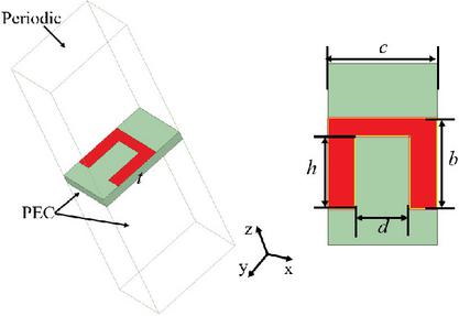
Figure 1 SSPP unit structure diagram.
Figure 2 presents the simulated dispersion characteristics of SSPP units and transmission lines with different slot depths. Slot depth serves as a key parameter to regulate the transmission characteristics of SSPP surface waves. From the perspective of electromagnetic field distribution, increasing enhances the “confinement effect” of the metal slot on the electromagnetic field which causes the field distribution of surface waves to concentrate more inside the slot, thereby expanding the spatial confinement region of the electromagnetic field and further enhancing the overall field confinement capability. Besides, the strengthened field confinement extends the wavelength of SSPP surface waves and reduces the cutoff frequency. Therefore, a detailed analysis of the slot depth is crucial when extracting the unit structure’s dispersion characteristics to ultimately obtain the optimal dispersion curve and slow-wave operating mode characteristics.
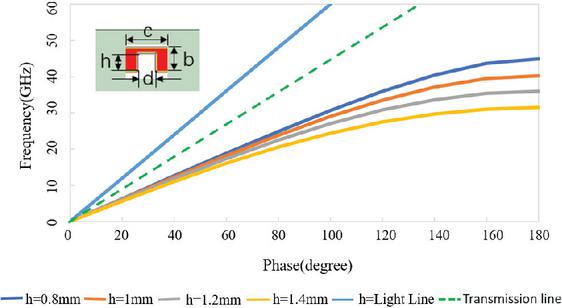
Figure 2 Simulated dispersion characteristic curves for different slot depths.
As the slot depth h increases from 0.8 mm to 1.4 mm, the deviation of the SSPP dispersion curve below the light line and the transmission line becomes more pronounced, and the cut-off frequency decreases continuously from 40 GHz to 29 GHz. At the same frequency, these dispersion curves exhibit a larger wave number K and a smaller wavelength than those of electromagnetic waves in vacuum. This slow-wave effect can effectively enable antenna miniaturization, which aligns with the compact design requirement of the proposed antenna.
B. Design and analysis of the unit antenna
Figure 3 shows the designed unit endfire antenna structure. The antenna is fabricated on a single-layer F4B dielectric substrate with a thickness of mm. The antenna consists of three core parts: a knife-shaped radiator, an SMA feed connector, and an SSPP transmission line. It features symmetrically distributed radiating elements, with the SSPP structure serving as the transmission line to guide electromagnetic energy. Additionally, a rectangular metal ground is designed at the bottom of the substrate to suppress backward radiation and optimize the contact area with the feed connector for stable power feeding.
The knife-shaped radiating patch adopts a Vivaldi gradient structure, which satisfies the following exponential function relationship:
| (1) | |
| (2) | |
| (3) |
Among them, , , , and represent the horizontal and vertical coordinates of the start point and end point of the curve, respectively. R denotes the curvature of the curve, with a value of 200.
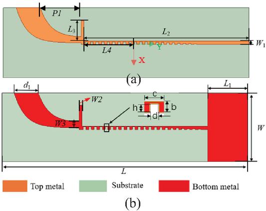
Figure 3 Specific structure diagram of unit antenna: (a) top view and (b) bottom view. , , , , , , , , , and (unit: mm).
The SSPP transmission line comprises two segments: 10 identical single-sided metal grooves (with mm) and nine gradient grooves (with varying from 0.04 mm to 1.2 mm), forming a two-part transition section. This gradient periodic unit structure offers three key advantages aligned with the design goals of the antenna. First, it achieves optimal impedance matching between the microstrip line and the SSPP transmission line. Second, it moderately enhances field confinement to ensure stable SSPP mode propagation without excessive energy leakage. Third, it enables smooth conversion from the quasi-TEM mode to the SSPP mode. To further broaden the impedance bandwidth and improve the endfire directivity of the antenna, a wide knife-shaped radiating patch is cascaded with the SSPP transmission line. This patch facilitates controlled energy radiation by weakening the field confinement of the final segment of the SSPP, a process essential for realizing endfire radiation.
C. Optimization and result analysis of unit antenna
Through structural analysis of the endfire antenna, the SSPP transmission line is identified as a key component regulating the performance of the antenna. Figure 4 (a) presents the optimization analysis of the slot depth h for the SSPP transmission line unit. As shown in Fig. 4, with the increase in h (from 1.1 mm to 1.4 mm), two resonance points within the target operating band gradually shift leftward, and the reflection coefficient curve shifts upward, which indicates degraded impedance matching performance. Based on the comprehensive analysis above, the slot depth mm is finally selected as the parameter for the SSPP unit.
The optimization results for the slot width d of the SSPP transmission line unit are presented in Fig. 4 (b). Comparative analysis shows that as d increases (from 1.0 mm to 1.4 mm), the operating resonant frequency point of the antenna does not shift, but the reflection coefficient S11 shifts upward gradually. This indicates that the impedance matching performance degrades significantly as d increases. Specifically, wider slots weaken the spatial confinement of the electromagnetic field by the metal slot, thus leading to unstable propagation of the SSPP mode. After comprehensive consideration of matching performance and mode stability, the slot width mm is selected for the SSPP unit structure.
Figure 4 (c) illustrates the effect of the stub on the S-parameters of the antenna. As the length of stub L3 increases from 4.5 to 8.5 mm, the impedance characteristic of the antenna is improved, and impedance matching is achieved when mm.
After setting the antenna parameters to the values shown in Figure 3, the antenna model is re-simulated. Figure 5 shows the main current distribution of the antenna at 8 GHz, revealing the primary radiation area of the antenna. Figure 6 (a) shows its S11 curve, confirming 6–10 GHz bandwidth that covers C-band and X-band. It also includes the simulated gain curve: gain is stable but not ideal for high performance, with a maximum of 6.26 dBi at 9.5 GHz. This limitation of the single-unit structure serves as the core driver for subsequent 14 array integration to enhance gain. Figure 6 (b) presents the simulated radiation pattern, demonstrating that the antenna achieves directional endfire radiation with a wide main beam and low backward radiation, which verifies that the antenna simultaneously exhibits good impedance matching performance and effective endfire radiation characteristics within the operating band.
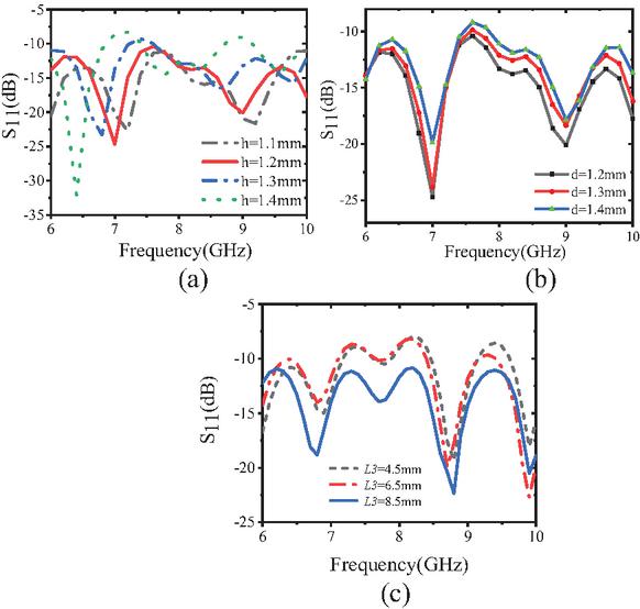
Figure 4 Simulated S-parameters with different parameters: (a) slot depth of h, (b) slot width of d, and (c) stub length of L3.
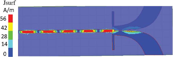
Figure 5 Current distribution at 8 GHz.
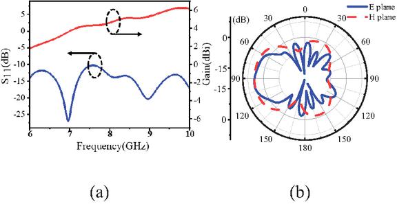
Figure 6 (a) S-parameters and gain of a single-unit endfire antenna and (b) 8 GHz direction diagram of a unit endfire antenna.
D. Design of array antennas and feed networks
To maintain the directional radiation performance of the single-unit endfire antenna and address its insufficient gain, a 14 array is adopted. This design enhances gain while retaining the compact planar structure for microwave system integration. A Wilkinson 1-to-4 microstrip equal-power divider serves as the feed network and is integrated with SSPP transmission lines, reducing overall size.
As shown in Fig. 7, the array has two copper layers on the F4B sheet. The top layer integrates a 14 SSPP feed network and the Wilkinson divider, the bottom layer has four symmetric SSPP lines and a full metallic ground. The ground suppresses backward radiation and supports the structure, while symmetrical layout ensures uniform energy distribution to avoid gain degradation.
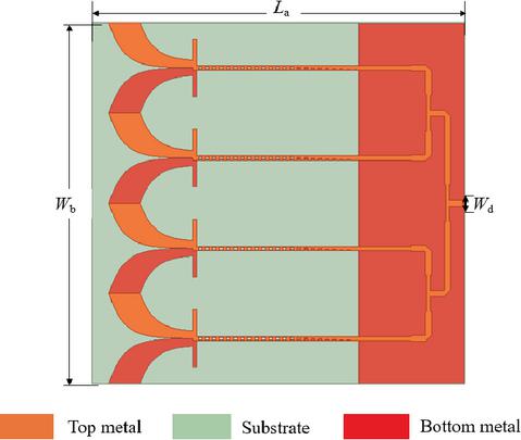
Figure 7 Endfire array antenna: , , and (unit: mm).
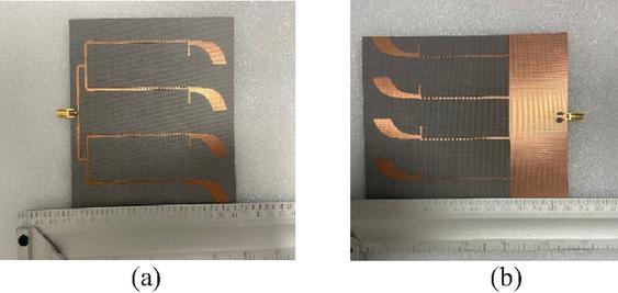
Figure 8 Photographs of the fabricated antenna: (a) top view and (b) bottom view.
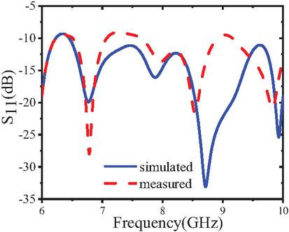
Figure 9 Simulated and measured S-parameters of the designed array antennas.
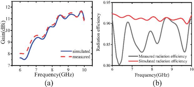
Figure 10 (a) Simulated and measured gains of the designed array antenna and (b) radiation efficiency of endfire antennas.
III. ANTENNA FABRICATION AND TESTING
Figure 8 shows the physical prototype of the proposed 14 endfire array antenna, and tests were conducted to validate its performance. Figure 9 compares the measured and simulated S-parameters of the proposed 14 endfire array. The measured 10 dB impedance bandwidth covers C-band high frequencies and X-band low frequencies, matching the target design. Figure 10 shows the gain of the array and measured radiation efficiency. Within 6–10 GHz, the measured gain of the array ranges from 8.2 to 11.6 dBi. This represents a gain enhancement of 4–5.4 dBi compared to
Table 1 Comparison with reported endfire antennas
| Ref. | (GHz) | Size L() W() | Band-width (%) | Average Efficiency (%) | Max Gain (dBi) |
| [14] | 16.6 | 5.84.44 | 11 | 95 | 12.1 |
| [16] | 10 | 2.930.51 | 20 | 98 | 13.3 |
| [17] | 5.5 | 3.330.74 | 7.4 | 85 | 7.86 |
| [18] | 19.5 | 6.21.4 | 35 | 90 | 15.2 |
| [19] | 12.5 | 6.592.92 | 120 | 92 | 10.7 |
| [20] | 6 | 2.330.25 | 67 | 54 | 7.9 |
| This Work | 8.0 | 30.85 | 50 | 87 | 11.6 |
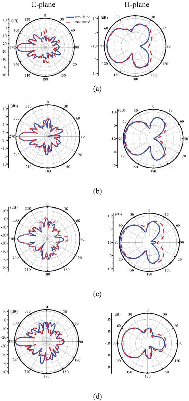
Figure 11 Simulated and measured radiation patterns in the E-plane (-plane) and H-plane (-plane) at (a) 7.5 GHz, (b) 8 GHz, (c) 8.5 GHz, and (d) 9 GHz.
the maximum gain of 6.26 dBi achieved by the single-unit SSPP endfire antenna, thereby verifying the effectiveness of the 14 array configuration in improving antenna gain. Measured average radiation efficiency is 87%, slightly lower than the simulated 91%. Figure 11 shows the measured and simulated radiation patterns of the array in the E-plane and H-plane. The simulated and measured patterns are basically consistent, only minor back lobe differences exist. Collectively, the measured results demonstrate excellent agreement with the simulation data. The minor deviations between the measured and simulated results are primarily caused by unavoidable fabrication tolerances.
Table 1 compares the proposed antenna with recent endfire antennas, where and are the center frequency and the wavelength at the center frequency, respectively. It has a wider bandwidth than [14, 16, 17, 18], while the antenna in [19] achieves a relatively wide bandwidth, it is too large for miniaturized integration, and the antenna in [20], though small and wideband, lacks radiation efficiency and gain. In contrast, the proposed antenna offers low profile, high integration, broadband capability, and stable radiation performance.
IV. CONCLUSION
This paper proposes a broadband high-gain endfire array antenna based on an SSPP transmission line. Endfire radiation is realized by truncating the SSPP structure to reduce field confinement. A 14 array is designed, with units connected via a Wilkinson power divider-based feed network. Featuring a low-profile and highly integrated structure, the antenna also possesses broadband performance and stable radiation characteristics, thus exhibiting great application potential in millimeter-wave communication, 5G/6G base stations, and satellite payloads.
ACKNOWLEDGMENT
This work was supported in part by the Teacher Research Program of Hefei University of Technology (JZ2019HGTB0093), Anhui Institute of Information Technology, the Research Fund of National Mobile Communications Research Laboratory, Southeast University (2023D05), and the Natural Science Foundation of Anhui Province (2208085MF161, JZ2022AKZR0453).
REFERENCES
[1] S.-Y. Zhou, S.-W. Wong, J.-Y. Lin, L. Zhu, Y. He, and Z.-H. Tu, “Four-way spoof surface plasmon polaritons splitter/combiner,” IEEE Microw. Wireless Compon. Lett., vol. 29, no. 2, pp. 98–100, Feb. 2019.
[2] X. Shen, T. Cui, D. Martin-Cano, and F. Garcia-Vidal, “Conformal surface plasmons propagating on ultrathin and flexible films,” Proc. Nat. Acad. Sci., vol. 110, no. 1, pp. 40–45, 2012.
[3] L. Liu, M. Chen, J. Cai, X. Yin, and L. Zhu, “Single-beam leaky wave antenna with lateral continuous scanning functionality based on spoof surface plasmon transmission line,” IEEE Access, vol. 7, pp. 25225–25231, 2019.
[4] W. L. Barnes, A. Dereux, and T. W. Ebbesen, “Surface plasmon sub-wavelength optics,” Nature, vol. 424, no. 6950, pp. 824–830, 2003.
[5] J. B. Pendry, L. Martín-Moreno, and F. J. García-Vidal, “Mimicking surface plasmons with structured surfaces,” Science, vol. 305, no. 5686, pp. 847–848, 2004.
[6] F. J. Garcia-Vidal, L. Martín-Moreno, and J. B. Pendry, “Surfaces with holes in them: New plasmonic metamaterials,” Journal of Optics and Pure and Applied Optics, vol. 7, no. 2, p. S97, 2005.
[7] A. Kandwal, Q. Zhang, X.-L. Tang, L. W. Liu, and G. Zhang, “Low-profile spoof surface plasmon polaritons traveling-wave antenna for near-endfire radiation,” IEEE Antennas Wireless Propag. Lett., vol. 17, no. 2, pp. 184–187, Feb. 2018.
[8] S. Ge, Q. Zhang, A. K. Rashid, G. Zhang, C.-Y. Chiu, and R. D. Murch, “Analysis of asymmetrically corrugated Goubau-line antenna for endfire radiation,” IEEE Trans. Antennas Propag., vol. 67, no. 11, pp. 7133–7138, Nov. 2019.
[9] L. Li, P. Chen, P. Zhu, and K. Yang, “A compact rejection filter based on spoof surface plasmon polaritons and folded split-ring resonators with controllable rejection bandwidth,” Applied Computational Electromagnetics Society (ACES) Journal, vol. 34, no. 09, pp. 1405–1410, Sep. 2019.
[10] H. C. Zhang, S. Liu, X. Shen, L. H. Chen, L. Li, and T. J. Cui, “Broad band amplification of spoof surface plasmon polaritons at microwave frequencies,” Laser & Photonics Reviews, vol. 9, no. 1, pp. 83–90, 2015.
[11] X. Gao, L. Zhou, X. Yu, W. Cao, H. Li, H. F. Ma, and T. Cui, “Ultra-compact surface plasmonic Y-splitter,” Optics Express, vol. 23, no. 18, p. 23270, 2015.
[12] J. Xu and Z. Zheng, “High-gain and wideband planar endfire antenna implemented via spoof surface plasmon polaritons and dielectric lens for x-band applications,” IEEE Antennas and Wireless Propagation Letters, vol. 22, no. 2, pp. 382–386, Feb. 2023.
[13] Y. Shi, Z. Fan, and C. Chen, “Wideband wide-angle SSPP-fed leaky-wave antenna with low side-lobe levels,” Applied Computational Electromagnetics Society (ACES) Journal, vol. 39, no. 10, pp. 916–926, Oct. 2024.
[14] L. Liu, M. Chen, and X. Yin, “Single-layer high gain endfire antenna based on spoof surface plasmon polaritons,” IEEE Access, vol. 8, pp. 64139–64144, 2020.
[15] X. Du, H. Li, and Y. Yin, “Wideband fish-bone antenna utilizing odd mode spoof surface plasmon polaritons for endfire radiation,” IEEE Trans. Antennas Propag., vol. 67, no. 7, pp. 4848–4853, July 2019.
[16] Q. Fu, H. Ni, G. Q. Luo, L. Zhu, and L. Liu, “A high aperture efficiency endfire antenna based on spoof surface plasmon polaritons,” IEEE Transactions on Antennas and Propagation, vol. 71, no. 1, pp. 50–57, Jan. 2023.
[17] D. Tian, R. Xu, G. Peng, J. Li, Z. Xu, and A. Zhang, “Low-profile high-efficiency bidirectional endfire antenna based on spoof surface plasmon polaritons,” in IEEE Antennas and Wireless Propagation Letters, vol. 17, no. 5, pp. 837–840, May 2018.
[18] F. Homayoon, A.-A. Heidari, and M.-M. Pezhman, “A low-profile high-performance endfire antenna based on spoof surface plasmon polaritons,” IEEE Antennas and Wireless Propagation Letters, vol. 22, no. 12, pp. 2891–2895, Dec. 2023.
[19] J. Y. Yin, H. C. Zhang, Y. Fan, and T. J. Cui, “Direct radiations of surface plasmon polariton waves by gradient groove depth and flaring metal structure,” IEEE Antennas and Wireless Propagation Letters, vol. 15, pp. 865–868, 2016.
[20] Y. Jiang, L. Liu, Y. Hu, and D. Jiang, “Wideband small aperture endfire antenna based on spoof surface plasmon polaritons,” IEEE Transactions on Antennas and Propagation, vol. 69, no. 8, pp. 5026–5031, Aug. 2021.
BIOGRAPHIES

Zhaoneng Jiang was born in Lianyungang, Jiangsu, China. He received the Ph.D. degree from Nanjing University of Science and Technology, Nanjing, in 2012. Since 2013, he has been engaged in research on numerical methods for computational electromagnetism. He is currently a Professor at Hefei University of Technology and a Distinguished Professor at Anhui Institute of Information Technology. He has authored or co-authored more than 100 papers in prestigious international journals and conferences and has served as a Program Committee Member for several international conferences. His current research interests include antennas and microwave devices.

Weixing Gao, a native of Zhoukou, Henan Province, China, obtained his master’s degree from Hefei University of Technology, in 2026. He has been engaged in the research of microwave antenna design since 2023.

Cheng Peng, a native of Yangzhou, Jiangsu Province, China, obtained his master’s degree from Hefei University of Technology in 2026. He has been engaged in the research of microwave antenna design since 2023.
ACES JOURNAL, Vol. 41, No. 3, 281–287
DOI: 10.13052/2026.ACES.J.410309
© 2026 River Publishers