Testing and Remote Communication of S-Parameters for Biomedical Applications Using Miniature VNA Hardware
Kenneth Y. Hora, Lisa Elmiladi, Atef Z. Elsherbeni, and Peter H. Aaen
Department of Electrical Engineering, Colorado School of Mines, Golden, CO 80401, USA
khora@mines.edu, lelmiladi@mines.edu, aelsherb@mines.edu, paaen@mines.edu
Submitted On: September 18, 2025; Accepted On: October 14, 2025
ABSTRACT
Remote sensing of lactate is important in both healthcare settings and monitoring athlete’s performance. Many approaches for noninvasive remote sensing of lactate use on-body resonator circuits that measure changes in S-parameters to determine lactate concentration. However, due to their large size, most commercial vector network analyzers (VNAs) are impractical for taking on-body measurements of moving participants. This paper presents an approach that uses smaller, hobbyist, VNAs to create practical on-body measurement systems.
Keywords: Bluetooth, lactate, MATLAB, NanoVNA, noninvasive sensing, python, VNA, wireless communication.
I. INTRODUCTION
Lactate monitoring within the human body can provide doctors, athletic trainers, and other health professionals with important information about their patients. This might include monitoring patients who have been in low oxygen situations or monitoring the exhaustion of athletes. Currently, many techniques for measuring lactate concentration require invasive procedures, such as pricking a finger to draw blood. There has been considerable development in noninvasive methods to measure lactate concentration, which often measure sweat, saliva, or tears; however, these methods often require characterization of these samples from external testing devices [1].
Recently, there has been additional development in RF and microwave-based devices examining whether the dielectric properties of lactate can be used with noninvasive, on-body sensors to detect lactate concentration [2, 3, 4, 5]. Often, these devices use resonators or similar circuitry and detect shifts in reflection and transmission coefficients over various frequencies to determine the concentration of lactate. While some approaches use transmission responses for characterization [2], these microwave circuits are often connected to vector network analyzers (VNAs) [3, 4, 5].
Current VNAs are often very large with respect to on-body sensors that require the measurement of S-parameters. Although some handheld VNAs do exist, such as the Keysight FieldFox [6], they are often still impractical for on-body measurements. However, within the past 4 years, hobbyist VNAs, such as the NanoVNA [7] and NanoVNA v2 by NanoRFE [8] have become widely available and provide relatively small footprints (though at the cost of measurement accuracy) that can be attached to a person for remote lactate sensing.
This paper explores the NanoVNA-H and NanoVNA v2 hardware as potential measurement devices for noninvasive lactate sensors.
II. NANOVNA HARDWARE
A. NanoVNA-H
The NanoVNA-H is a compact device that boasts a variety of hardware capabilities and interfaces designed to cater to a broad spectrum of RF measurement needs. It includes two ports, labeled Port 1 and Port 2, and is capable of measuring S11 and S21. The NanoVNA-H is equipped with a simple user interface, consisting of a touchscreen display that can be detached to render the device more compact, enhancing portability for field use or in testing environments where physical cables are impractical or hazardous. Additional specifications of the NanoVNA-H may be found in Table 1 [7, 9].
Table 1: NanoVNA-H characteristics
| Frequency Range | 50 kHz to 900 MHz |
| Frequency Resolution | 100 Hz |
| Noise Floor | -40 dB |
| Max Sweep Points | 1024 |
| Interface | micro-USB, hardware UART |
Moreover, NanoVNA-H hardware is designed to interface seamlessly with numerous software and platforms. One of the key interfaces is the UART (Universal Asynchronous Receiver/Transmitter), a hardware communication protocol that facilitates serial communication between devices [10]. This interface allows the NanoVNA-H to communicate over Bluetooth with modules like the HC-05, enabling wireless connectivity. The Bluetooth module connects to the VNA via jumper wires attached to the VCC, Tx and Rx pins, and GND. The Tx and Rx pins enable bidirectional communication, allowing commands to be sent and data to be received over UART. This wireless capability not only extends the device’s usability in different settings but also facilitates real-time data transfer to laptops or smartphones, eliminating the limitations imposed by cables.
B. NanoVNA v2
The NanoVNA v2 is an improved hobbyist VNA created by NanoRFE, but it is not based on the original NanoVNA-H design or derivatives [8]. Instead, it was designed to be more performant than previous hardware and was not designed to be compatible with the NanoVNA-H.
The NanoVNA v2 is a two-port network analyzer, capable of measuring S11 and S21. The authors used a NanoVNA v2 (see Table 2) [11].
Table 2: NanoVNA v2 characteristics
| Frequency Range | 50 kHz to 3 GHz |
| Frequency Resolution | 10 kHz |
| Noise Floor | 40 dB |
| Max Sweep Points | 1024-65536 (firmware & PC dependent) |
| Interface | micro-USB |
The NanoVNA v2 will interface with a host computer via USB and connects as a virtual serial port. Binary commands can be issued to the device to set sweep parameters or read data from the device [11].
III. WIRELESS COMMUNICATION INTERFACE WITH NANOVNA-H
The NanoVNA-H, while a compact and capable device for RF measurements, typically requires a direct USB connection for data interfacing, which limits its applicability for dynamic and remote sensing applications. This section presents the integration of an HC-05 wireless communication module, to enable remote operation and data acquisition from the NanoVNA-H.
The HC-05 module was selected for its ubiquity, ease of use, and sufficient data rate to transmit S-parameters effectively. Interfacing the module required firmware modifications to the NanoVNA-H, which were implemented following the support provided by DaveLapp [12]. The firmware release leverages the UART1 port for wireless data transmission when USB is not active.
A. Bluetooth module configuration
The HC-05 Bluetooth module was initially configured with AT commands to set the device name and baud rate, ensuring seamless communication with the NanoVNA-H. These configurations were critical for establishing a reliable link and compatibility with various operating systems and host devices.
B. Hardware configuration
The interfacing between the NanoVNA-H and the Bluetooth module involved connecting the Tx and Rx pins to the corresponding UART pads on the NanoVNA’s printed circuit board (PCB). This hardware setup facilitated a virtual serial port over Bluetooth, allowing for the wireless transmission of measurement data. The UART connections are shown in Fig. 1. The device under test (DUT) was attached to Port 1 of the VNA so that it can be measured. This is shown in Figs. 1 and 2.
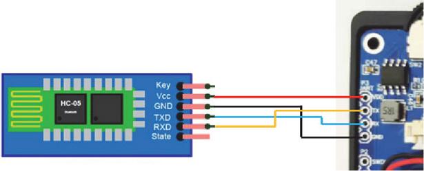
Figure 1: UART interface pin connections between HC-05 Bluetooth module and NanoVNA-H.
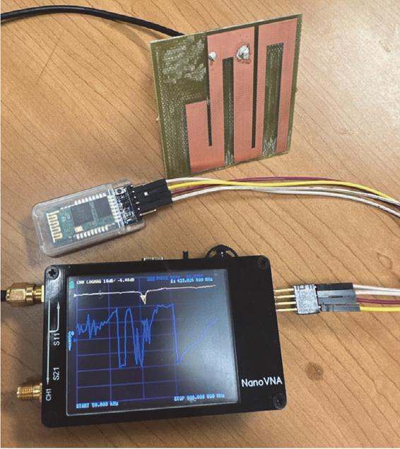
Figure 2: NanoVNA attached to HC-05 Bluetooth module via UART connections and a sensor antenna.
C. Software configuration
To capture and visualize the data wirelessly transmitted by the NanoVNA-H, a MATLAB script was developed and is listed in [13]. This script interfaces with the Bluetooth module to receive data, applies necessary calibrations, and plots the S-parameters for real-time analysis. The use of MATLAB provided robust data manipulation and visualization capabilities, essential for interpreting the RF characteristics related to lactate concentration.
A Python library was also developed to interface the NanoVNA-H to a host computer, allowing devices without MATLAB to perform the same functions [13]. It allows users to control the NanoVNA, acquire S-parameters data, and process this data for RF analysis.
D. Measurement saving and transfer
The wireless communication setup was tested in various scenarios to ensure stability and accuracy. The tests would involve remote monitoring of lactate concentrations using resonator circuits attached to the human body. Figure 3 represents an example resonator used to take microfluidic lactate samples. The wireless NanoVNA-H proved to be a valuable tool for dynamic testing environments where conventional VNAs are unsuitable due to size and the necessity of a physical connection.
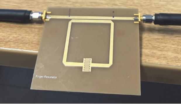
Figure 3: Finger resonator setup used for microfluidic measurements that mimic lactate concentrations.
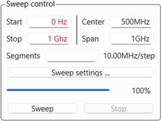
Figure 4: NanoVNA Saver sweep control interface.
In this experiment, the NanoVNA-H was connected via Bluetooth to a computer running the NanoVNA Saver application, which is available as an open-source application on GitHub [14]. This setup allowed for convenient and wireless data acquisition from the NanoVNA-H, streamlining the measurement process and enhancing mobility. The control panel for the application is shown in Fig. 4. The measurement results downloaded from NanoVNA Saver are shown in Fig. 5. The Smith chart, log magnitude, and other relevant plots were generated in NanoVNA Saver, enabling detailed examination of the DUT characteristics.
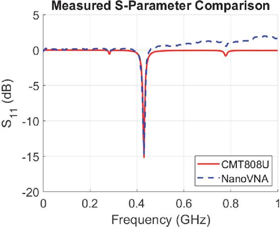
Figure 5: Comparison of measured S-parameters from CMT808U laboratory VNA (calibrated) and NanoVNA (uncalibrated) for the sensor antenna shown in Fig. 2.
Shown in Fig. 5 are S-parameter measurements for an on-body glucose-sensing antenna developed by Ostrem, Kringlen, and Evanovich in free space [15]. For comparison, the same antenna is measured on a CMT-808U laboratory VNA, calibrated on Port 1 using an S2611 Calibration Kit. The antenna measurements were initially taken in free space in the range 0-1 GHz, providing baseline S-parameter data for comparison.
For this antenna, the NanoVNA-H measured the resonance of the antenna around 430 MHz to an accuracy 1 MHz. The magnitude of the reflection coefficient is within 1 dB at the same measured frequency. It should be noted that measurements taken on the NanoVNA express a reflection coefficient 0 dB even though the device measured is passive. This is because the NanoVNA cannot transmit calibrated measurements over UART. In applications where calibration is necessary, measurements of a calibration kit may be taken by a user prior to use and have calibration applied through software after measurements are complete.
IV. WIRELESS COMMUNICATION INTERFACE WITH NANOVNA V2
Due to the hardware differences from the NanoVNA-H, the NanoVNA v2 does not provide a hardware UART port that can be used to interface the NanoVNA directly to a computer via a USB-to-serial bridge. Instead, the module can only connect via USB, which establishes a virtual USB Communication Device Class (CDC) serial port between the NanoVNA and its host computer.
A. Hardware configuration
Hardware setup for the NanoVNA v2 is relatively simple. The DUT is connected to Port 1 (and Port 2, if applicable) via a coaxial cable as shown in Figs. 6 and 7. The NanoVNA is then connected via USB to a host computer. In this paper, the NanoVNA was connected to a host laptop running Windows 10. A smaller, portable device such as a Raspberry Pi may be used in lieu of the laptop to allow all hardware to be attached to a person, and standard communication protocols such as WiFi or Bluetooth may be used to transfer datawirelessly.
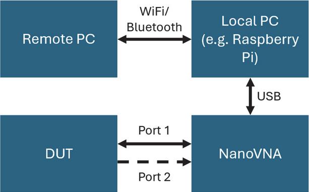
Figure 6: Connection diagram of NanoVNA v2 for remote measurement.
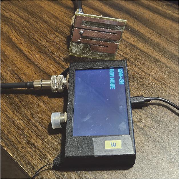
Figure 7: Test configuration of the sensor antenna using NanoVNA v2 and a host computer.
B. Software configuration
Using the USB data interface specification from the NanoRFE NanoVNA v2 Manual and example firmware provided on the NanoVNA v2 GitHub repository [16], a Python library was developed to simplify interfacing of the NanoVNA v2 with a host computer [13]. This Python library uses the pySerial library for serial interfacing so that the source code is compatible with Windows, Linux, or MacOS.
Due to firmware limitations, some sweep settings of the NanoVNA v2 may yield bad measurement results. For example, it was found that the number of sweep points must be a power of 2 if more than 256 samples are being requested from the NanoVNA. Otherwise, some repeated data will be sent from the NanoVNA v2.
C. Measurement saving and transfer
Using the software developed to interface with the NanoVNA v2, a sweep of S11 of the attached antenna was measured and plotted as shown in Fig. 7. The developed software is also able to export the measured parameters to a touchstone file, which may then be imported into software such as MATLAB for further analysis. Files can be retrieved from the host computer to other remote computers using protocols like SCP or SFTP. The same experiment using the sensor antenna developed by Collin Kringlen was used to examine the measurement accuracy of the NanoVNA v2 when connected remotely.
When examining the major resonance of the antenna at 2.1 GHz, the NanoVNA has a measurement accuracy of within 10 MHz. It does not, however, measure the magnitude of the S-parameters well, displaying over 5 dB of difference when compared to the NanoVNA v2. This is an expected tradeoff given the price of the NanoVNA v2 compared to a professional VNA, though application where only a shift in resonant frequency is examined could greatly benefit from the size reduction in measurement hardware. This setup also suffers from the same calibration issues where it may report a reflection coefficient 0 dB for a passive device, though software libraries such as scikit-rf may be used to measure a calibration kit and apply the calibration to the measured data [17].
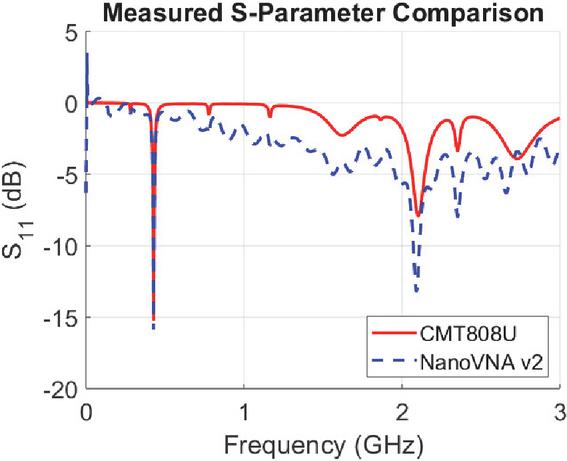
Figure 8: S11 plot of measured antenna on NanoVNA v2 (uncalibrated) against Copper Mountain CMT808U (calibrated).
V. DISCUSSION
This paper proposes a simple system for making noninvasive on-body measurements of S-parameters with small-footprint, low-cost VNA technology. However, there are potential areas where the software developed can be further improved.
First, it should be noted that direct readings from the NanoVNA v2 do not reflect any calibration applied to the device, so calibration needs to be applied in the software on the host computer. This is evident in Fig. 8 where S dB at some points. Calibration can be done using a library such as scikit-rf [17] or by custom implementation, though it has yet to be implemented in the currently developed Python codebase.
The developed software may also be imported as a class into other Python modules, which can allow users to develop real-time streaming of S-parameters or data analysis. If good models are created that relate a shift in S11 or S21 to lactate concentrations, this would enable real-time on-body lactate monitoring.
VI. CONCLUSIONS
The integration of microwave sensor technology with wireless data interfaces in the NanoVNA-H and NanoVNA v2 paves the way for a new era in biomedical sensing. This research not only contributes to the field of biomedical engineering but also sets a precedent for future innovations in portable measurement technologies.
Through the use of a NanoVNA, this study has demonstrated the feasibility of remote lactate sensing, which has significant implications for healthcare and athletic performance monitoring. The successful interfacing of the NanoVNA-H with Bluetooth communication modules and the development of accompanying software in MATLAB and Python highlights the potential for creating a user-friendly, cost-effective, and portable solution for real-time lactate monitoring. Although an additional single-board computer or similar device is needed to enable similar functionality on the NanoVNA v2, the ability to wirelessly interface with it provides additional opportunities that the NanoVNA does not provide, especially enabling measurement of S-parameters in the 900 MHz to 3 GHz range.
REFERENCES
[1] F. Alam, S. RoyChoudhury, A. H. Jalal, Y. Umasankar, S. Forouzanfar, N. Akter, S. Bhansali, and N. Pala, “Lactate biosensing: The emerging point-of-care and personal health monitoring,” Biosensors and Bioelectronics, vol. 117, pp. 818–829, Oct. 2018.
[2] M. Baghelani, Z. Abbasi, M. Daneshmand, and P. E. Light, “Non-invasive lactate monitoring system using wearable chipless microwave sensors with enhanced sensitivity and zero power consumption,” IEEE Transactions on Biomedical Engineering, vol. 69, no. 10, pp. 3175–3182, Oct. 2022.
[3] A. Mason, O. Korostynska, J. Louis, L. E. Cordova-Lopez, B. Abdullah, J. Greene, R. Connell, and J. Hopkins, “Noninvasive in-situ measurement of blood lactate using microwave sensors,” IEEE Transactions on Biomedical Engineering, vol. 65, no. 3, pp. 698–705, Mar. 2018.
[4] T. Reinecke, J.-G. Walter, T. Kobelt, A. Ahrens, T. Scheper, and S. Zimmermann, “Design and evaluation of split-ring resonators for aptamer-based biosensors,” Journal of Sensors and Sensor Systems, vol. 7, no. 1, pp. 101–111, Feb. 2018.
[5] A. Mason, O. Korostynska, M. Ortoneda-Pedrola, A. Shaw, and A. Al-Shamma’a, “A resonant co-planar sensor at microwave frequencies for biomedical applications,” Sensors and Actuators A: Physical, vol. 202, pp. 170–175, Nov. 2013.
[6] Keysight, FieldFox Handheld RF and Microwave Analyzers [Online]. Available: https://www.keysight.com/us/en/products/network-analyzers/fieldfox-handheld-rf-microwave-analyzers.html.
[7] About NanoVNA, NanoVNA |Very tiny handheld Vector Network Analyzer. [Online]. Available: https://nanovna.com.
[8] About NanoVNA, NanoVNA v2 Official Site [Online]. Available: https://nanorfe.com/nanovna-v2.html.
[9] L. Rothman, NanoVNA Console Commands [Online]. Available: https://4ham.ru/wp-content/uploads/2020/05/NanoVNA_Console_Commands_Dec-9-19-1.pdf.
[10] NanoVNA Hardware [Online]. Available: https://oristopo.github.io/nVhelp/html/hardware.htm.
[11] User Manual - NanoVNA V2, NanoVNA V2 Official Site [Online]. Available: https://nanorfe.com/nanovna-v2-user-manual.html#specifications.
[12] Firmware with UART support for nanoVNA-H [Online]. Available: https://github.com/DaveLapp/NanoVNA-H/releases/tag/shell-on-UART-HugenJan2020.
[13] K. Y. Hora, L. K. Elmiladi, A. Z. Elsherbeni, and P. H. Aaen, Nano VNA Remote Communication of S-Parameters [Online]. Available: https://aces-society.org/software/freeware/NanoVNA_Code_Appendix_LisaElmiladi.zip.
[14] NanoVNA-Saver/nanovna-saver [Online]. Available: https://github.com/NanoVNA-Saver/nanovna-saver/releases.
[15] S. Ostrem, C. Kringlen, C. Evanovich, A. Elsherbeni, and P. Aaen, “Towards the design of a non-invasive glucose monitoring sensor,” in 2024 International Applied Computational Electromagnetics Society (ACES) Symposium, pp. 1–2, May 2024.
[16] nanovna-v2/NanoVNA2-firmware [Online]. Available: https://github.com/nanovna-v2/NanoVNA2-firmware.
[17] A. Arsenovic, J. Hillairet, J. Anderson, H. Forstén, V. Rieß, M. Eller, N. Sauber, R. Weikle, W. Barnhart, and F. Forstmayr, “scikit-rf: An Open-Source Python Package for Microwave Network Creation, Analysis, and Calibration [Speaker’s Corner],” IEEE Microwave Magazine, vol. 23, no. 1, pp. 98–105, Jan. 2022.
BIOGRAPHIES

Kenneth Y. Hora received his B.S. in Electrical Engineering in 2025 with minors in Computer Engineering and Public Affairs at the Colorado School of Mines in Golden, CO, USA. He is continuing his education at Mines, pursuing an M.S. in Electrical Engineering. His research interests include microprocessor VLSI design, embedded systems, antennas, and electromagnetic simulation.

Lisa Elmiladi received her B.S. and M.S. in Electrical Engineering in 2024 and 2025, respectively, from the Colorado School of Mines in Golden, CO, USA, completing both degrees with distinction. Her research interests include VLSI circuit design, biomedical devices, antennas, computer architecture, and electromagnetics. With a keen interest in the practical and theoretical aspects of her field, Elmiladi is intent on furthering her education with a Ph.D. in Electrical Engineering.

Atef Z. Elsherbeni received his Ph.D. in Electrical Engineering from Manitoba University, Winnipeg, Manitoba, Canada, in 1987. He started his engineering career as a part-time Software and System Design Engineer from March 1980 to December 1982 at the Automated Data System Center, Cairo, Egypt. From January to August 1987, he was a Post-Doctoral Fellow at Manitoba University. Elsherbeni joined the faculty at the University of Mississippi in August 1987 as an Assistant Professor of Electrical Engineering and progressed to the full professor and the Associate Dean of the College of Engineering for Research and Graduate Programs. He joined the Electrical Engineering and Computer Science (EECS) Department at Colorado School of Mines in August 2013. Elsherbeni is an IEEE Life Fellow and ACES Fellow. He is the Editor-in-Chief for Applied Computational Electromagnetics Society (ACES) Journal, and a past Associate Editor to Radio Science. He was Chair of the Engineering and Physics Division of the Mississippi Academy of Science, Chair of the Educational Activity Committee for IEEE Region 3 Section, and past President of ACES Society. He recently received the 2023 IEEE APS Harington-Mittra Award for his contribution to computational electromagnetics with hardware acceleration and the ACES 2025 Computational ElectromagneticsAward.

Peter H. Aaen received the B.A.Sc. degree in engineering science and the M.A.Sc. degree in electrical engineering from the University of Toronto, Toronto, ON, Canada, in 1995 and 1997, respectively, and the Ph.D. degree in electrical engineering from Arizona State University, Tempe, AZ, USA, in 2005. He was the Manager of the RF Division, RF Modeling and Measurement Technology Team, Freescale Semiconductor, Inc., Tempe, AZ, USA, a company which he joined in 1997, then the Semiconductor Product Sector, Motorola Inc. In 2013, he joined the Faculty of Engineering and Physical Sciences, University of Surrey, Guildford, UK, where he was a Reader of microwave semiconductor device modeling. He was also the Director of the Nonlinear Microwave Measurement and Modeling Laboratory, a joint University of Surrey/National Physical Laboratory, and the Director of National Physical Laboratory – South of England, Guildford UK. In 2019, he joined the Colorado School of Mines as a Professor and Head of the Electrical Engineering Department. He co-authored Modeling and Characterization of RF and Microwave Power FETs (Cambridge University Press, 2007). Aaen is a member of the Microwave Theory and Techniques and Electron Device Societies, served as an Executive Committee Member and Vice-President of the Automatic RF Techniques Group, and was the Chair of the IEEE Technical Committee (MTT-1) on Computer-AidedDesign.
ACES JOURNAL, Vol. 40, No. 11, 1126–1132
DOI: 10.13052/2025.ACES.J.401109
© 2025 River Publishers