Wideband Dual-Polarized Metasurface Antenna Array with High Isolation
Yue-Chen Liu1, Xiaoyun Qu2, Cheng Ju1, and Wei-Hua Zong1*
1College of Electronics and Information Qingdao University
Qingdao 266000, China
liuyuechen@qdu.edu.cn, jucheng719@qdu.edu.cn, weihuazong@126.com*
*Corresponding Author
2Shandong Institute of Space Electronic Technology
Yantai, China
selina.qu@163.com
Submitted On: October 01, 2025; Accepted On: March 08, 2026
Abstract
This paper presents a dual-polarized 14 antenna array with wide bandwidth and high isolation. The antenna element consists of three metallic layers, a 44-unit metasurface (MTS) on the top layer, a patch fed by two ports on the middle layer, and a ground plane on the bottom layer. By exciting different feeding ports, the antenna achieves X-axis linear polarizations (X-LP) or Y-axis linear polarizations (Y-LP). Isolation slots etched on the patch, combined with a via-hole structure, effectively block the coupling between ports and improve port isolation. Experimental results demonstrate that the proposed antenna achieves an impedance bandwidth of 17.4% (4.975–5.925 GHz), with dB and dB. The measured peak gain attains 12.5 dBi.
Keywords: Antenna array, dual polarization, high isolation, low profile, metasurface (MTS)..
1 INTRODUCTION
Dual-polarized antennas enable Multiple-Input Multiple-Output (MIMO) polarization diversity by simultaneously transmitting and receiving two orthogonal polarizations, such as horizontal/vertical polarization and 45∘ cross-polarization. This capability helps reduce co-channel interference, mitigate multipath effects, and improve communication capacity along with data transmission rates. As a result, such antennas are widely used in macro and micro base stations, access point (AP) systems, and terminal devices for applications in mobile communications, Wireless Local Area Networks (WLAN), and Internet of Things (IoT). The design of dual-polarized antennas entails addressing several challenges: minimizing port coupling, suppressing cross-polarization, and simultaneously achieving wideband impedance matching and high gain, all with the overarching goal of satisfying the stringent application demands of modern communication systems.
Extensive research has been conducted on dual-polarized antennas, which mainly fall into two categories: dipole antennas [1, 2, 3, 4, 5, 6, 7] and planar patch antennas [8, 9, 10, 11, 12, 13, 14]. For dipole antennas, two orthogonal radiators are employed to achieve dual polarization. These two radiators are isolated from each other without any metallic connection, and their respective feeding strips are arranged in a crossed pattern on different layers, resulting in high port isolation. Metallic reflectors are placed beneath the radiators, and a large air gap is maintained between the reflectors and radiators to achieve directional radiation. However, this leads to the drawback of a large antenna volume.
Planar patch antennas feature a compact size, as they utilize a single patch with two feeding ports to realize dual polarization. Since the two polarizations share the same patch, strong mutual coupling occurs. Existing decoupling techniques include metamaterial-based electromagnetic bandgap (EBG) structures between the radiation patch and ground plane [8], shorting pins loaded between the radiator and ground [9], open- and short-circuited stubs added to the feeding strips [10], the use of coupled feeding methods [11, 12, 13], and slot etching on the patch combined with shorted feeding strips [14].
Antenna arrays are designed to improve antenna gain. Coupling between antenna elements needs to be considered in array antenna design. The commonly used decoupling techniques include adopting parasitic patches [10, 15, 16, 17, 18], defected ground structures [19, 20], adding isolating walls and metasurface (MTS) [21, 22], and reducing the radiator’s size by means of bending its shape [23].
In applications involving antennas for wearable devices, unmanned aerial vehicles (UAVs), compact passenger vehicles, automobiles, and micro-satellites, miniaturization of antennas is a core requirement. Patch antennas without an air gap are more suitable for integration in these scenarios. However, they suffer from a narrow bandwidth. The antennas exhibit much narrower bandwidths: 1.4% (lower band) and 0.8% (upper band) in [8], and 2.2% in [10]. In contrast, antennas with an air gap achieve significantly wider bandwidths: 51.3% in [9], 38.7% in [11], and 21.9% in [14].
This paper aims to design a dual-polarized patch antenna with wide bandwidth and high isolation. An MTS is adopted to enhance antenna bandwidth. Meanwhile, isolation slots are etched on the radiating patch, and a via-hole structure is integrated to improve isolation. Additionally, a 14 antenna array is proposed to improve antenna gain.
2 ANTENNA ELEMENT DESIGN AND MEASUREMENT
2.1 Configuration of antenna element
The configuration of the proposed antenna is shown in Fig. 1. The antenna consists of three metal layers, a 44-unit MTS on the top layer, a square patch loaded with slots on the middle layer and a ground plane on the bottom layer, printed on two pieces of FR-4 (, ) substrate. The two substrates are tightly bonded without air gap between them. Linear polarization (LP) along x/y axial is obtained by feeding Port 1/Port 2. The patch is etched with 33 slots, with each slot loaded with a via hole, to enhance isolation between the two feeding ports. The antenna dimensions are mm, mm, mm, mm, mm, mm, mm, mm, mm, mm, mm, mm, mm, mm, mm, and mm.
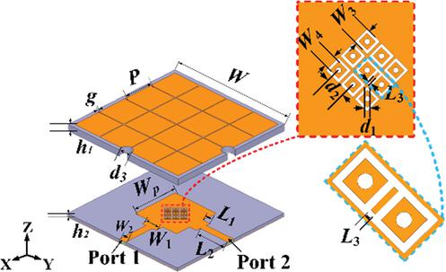
Figure 1 Configuration of the proposed antenna.
2.2 Bandwidth enhancement using MTS
Two reference antennas are illustrated in Fig. 2. Ant.2 is derived from the proposed antenna by removing the slots and via-holes. Ant.1 is obtained by further removing the MTS from Ant.2. The S-parameters of these two antennas are presented in Fig. 3. For Ant.1, its resonant frequency is 5.15 GHz, and its bandwidth is 5.1–5.25 GHz (with S11 10 dB). For Ant.2, adding the MTS layer excites a second resonance at 5.95 GHz. Its bandwidth is improved to 4.85–6.3 GHz. However, the coupling between Port 1 and Port 2 of Ant.2 is stronger than that of Ant.1. Specifically, S12 15 dB in 5.2–5.35 GHz and S12 20 dB in 5.1–5.65 GHz.
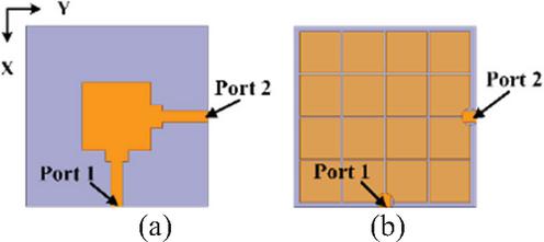
Figure 2 Reference antennas in bandwidth enhancement design (a) Ant.1 and (b) Ant.2.
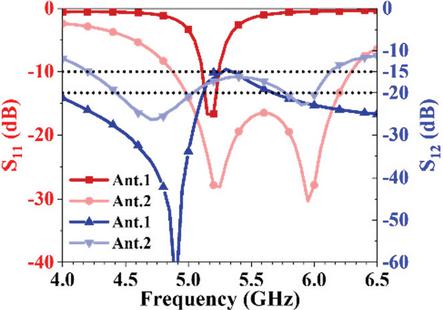
Figure 3 Simulated S parameters of Ant.1 and Ant.2.
The size of the radiation patch can be calculated using the following formula [24]:
| (1) |
In consideration of the dual-port, dual-polarized design and required structural symmetry, the square radiation patch is dimensioned as mm.
Loading MTS is an effective method to improve the antenna bandwidth. After adding the MTS structure, the antenna frequency shifts toward the low-frequency. is optimized to adjust the frequency. As shown in Fig. 4, with mm, the S11 is below 10 dB over 4.54–6.17 GHz. It provides the optimal bandwidth and impedance matching performance. mm is adopted as the width of the antenna radiation patch.
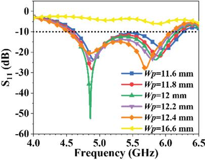
Figure 4 The effect of on S11.
As shown in Figs. 5 and 6, the dimensions of the MTS structure affect S11. When mm, S11 is below 10 dB in 4.54–6.17 GHz. This is the widest bandwidth among all cases. As shown in Fig. 6, the antenna exhibits the optimal impedance matching at mm, with S11 below 10 dB over 4.54–6.17 GHz. Therefore, mm and mm are determined.
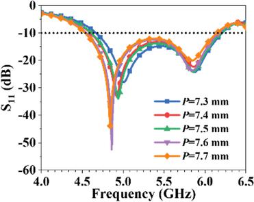
Figure 5 Effect of on S11.
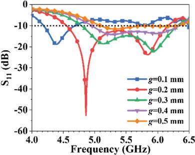
Figure 6 Effect of on S11.
2.3 Decoupling enhancement adopting slots with via holes
Based on Ant.2, geometry of the radiation patch is designed for decoupling as shown in Fig. 7. For Ant.3, two independent slots lading with via holes are etched in the patch. As shown in Fig. 8, compared with Ant.2, the S12 of Ant.3 decreases in 5.3–5.85 GHz. However, it remains higher than 20 dB in 4.8–5.5 GHz. With the addition of shorted slots, the coupling is further reduced. Ant.4, which incorporates 3 slots, exhibits a 1.6 dB lower coupling than Ant.3 in 5.45–5.5 GHz. Nevertheless, its coupling is still above 20 dB in 4.9–5.45 GHz. Ant.5, which is configured with a 33 array of independent slots, exhibits further reduced coupling. However, its S12 remains slightly higher than 20 dB in 5–5.25 GHz.
The proposed antenna is modified from Ant.5. Metal segments 1 and 2, located below the patch’s diagonal, are connected. The rectangular ring slot is extended accordingly. For this antenna, the port isolation is below 20 dB over 4.3–5.61 GHz.
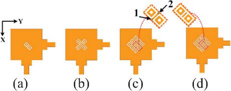
Figure 7 Decoupling geometries of the radiation patch (a) Ant.3, (b) Ant.4, (c) Ant.5, (d) Proposed.
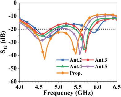
Figure 8 Isolation of Ant.2-5 and prop. antenna.
Figure 9 illustrates the effect of the distance between vias () on S11. mm provides the minimum S11 and optimal impedance matching and is thus adopted.
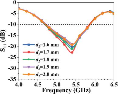
Figure 9 The effect of on S11.
Figure 10 illustrates the variation of the antenna’s port isolation with the slot extension length . When mm, the nine square slots are in an independent state, with one via hole loaded on each slot. In this case, S12 is slightly higher than 20 dB over 5–5.25 GHz. When mm, there is no significant improvement in the S12, and the S12 is basically the same as that when mm. However, when mm, the S12 is significantly improved. S12 falls below 20 dB in 4.3–5.61 GHz. Nevertheless, the bandwidth of this band is slightly reduced compared with that when mm.
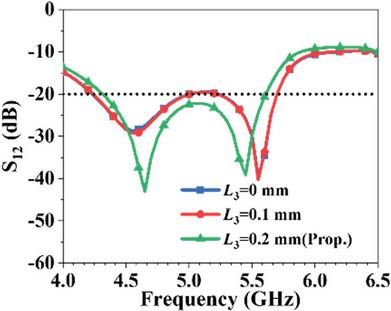
Figure 10 The effect of on S12.
2.4 Fabrication and measurement of the proposed antenna element
To verify its performance, the proposed antenna was fabricated and measured. Figure 11 presents a photograph of the fabricated antenna. The measured S11, S12, and realized gain of the antenna are shown in Fig. 12. For LP states, the overlapping impedance bandwidth of the antenna ranges 4.875–5.745 GHz, while its isolation bandwidth (with S12 20 dB) spans 4.4–6.1 GHz, and the realized gain of 4–6.2 dBi is achieved within this impedance bandwidth.
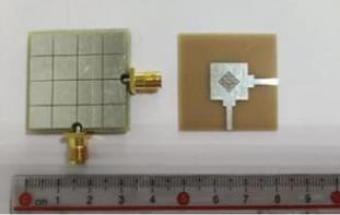
Figure 11 Top layer and bottom layer of the fabricated antenna.
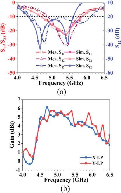
Figure 12 Measured (a) S-parameters and (b) gain of the proposed antenna.
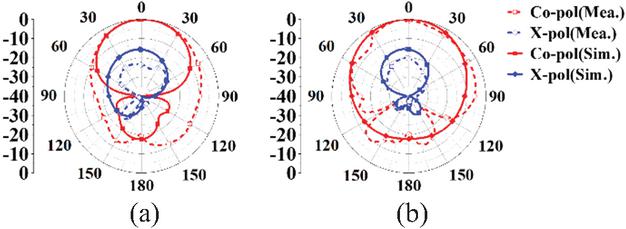
Figure 13 Radiation pattern at 5.1 GHz in YOZ plane (a) X-LP and (b) Y-LP.
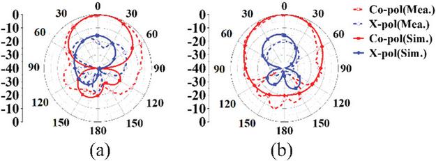
Figure 14 Radiation pattern at 5.45 GHz in YOZ plane (a) X-LP and (b) Y-LP.
Radiation patterns in Figs. 13–14 show the measured and simulated results of the antenna under X-axis linear polarizations (X-LP) and Y-axis linear polarizations (Y-LP) at 5.1 GHz and 5.45 GHz in YOZ plane, with cross-polarization levels exceeding 15 dB in all cases.
3 ANTENNA ARRAY DESIGN AND MEASUREMENT
3.1 Antenna array design
A 14 antenna array was designed as shown in Fig. 15. The distance (dx) between two adjacent elements center is 40 mm. There is an 8 mm gap between adjacent antenna elements.
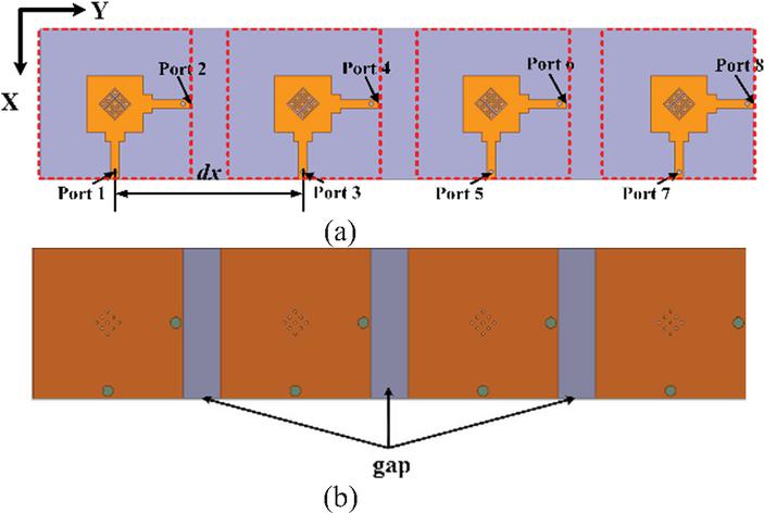
Figure 15 Configuration of the proposed antenna array (a) top layer and (b) bottom layer.
The dx affects the isolation between adjacent ports. Since the isolation between adjacent ports is highly similar, only S13 is presented in Fig. 16 (a). It can be observed that S13 improves as dx increases. At mm, S13 is below 20 dB in the range of 4.65–5.64 GHz. Considering structural compactness, the dx is finally set to 40 mm. Figure 16 (b) illustrates that the isolation between two ports of one element and those of two adjacent elements is below 20 dB when mm.
The port reflection coefficients deteriorate when four elements form the antenna array. As illustrated in Fig. 17 (a), the reflection coefficients S44, S55, and S66 exceed 10 dB within the frequency range of 5.1–5.25 GHz. By introducing gaps into the antenna ground plane, the reflection coefficients of all ports are reduced to below 10 dB, as depicted in Fig. 17 (b).
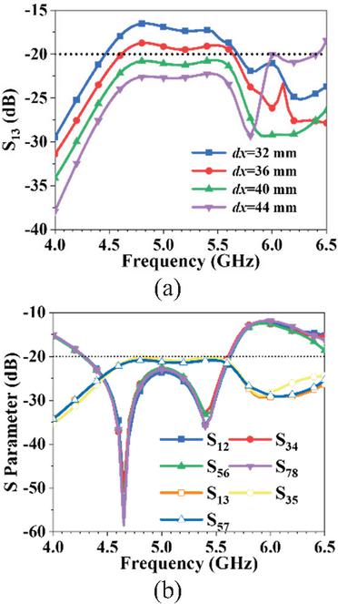
Figure 16 Isolation between ports (a) the effect of and (b) mm.
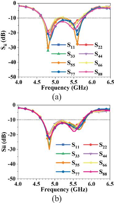
Figure 17 The effect of antenna ground connectivity on Sii (a) without gap and (b) with gap.
3.2 Fabrication and measurement of the antenna array
To verify the feasibility of the proposed antenna, the antenna prototype was fabricated and measured. To enable simultaneous excitation of the array antenna’s horizontal/vertical ports, the antenna ports were connected via a 1-to-4 power divider, as shown in Fig. 18.
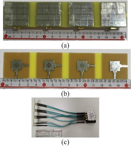
Figure 18 Photographs of the array antenna prototype (a) top layer, (b) bottom layer, and (c) power divider.
The measured impedance bandwidth, isolation, gain, and efficiency of the antenna are shown in Fig. 19. For LP states, the overlapping impedance bandwidth ranges 4.975–5.925 GHz. The isolation bandwidth (with dB) spans 4.3–6 GHz, the peak realized gain within this impedance bandwidth reaches 12.5 dBi, and the efficiency can reach 75.4%.
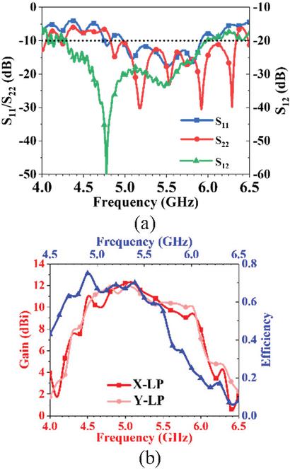
Figure 19 Measured (a) S-parameters and (b) gain of the proposed antenna.
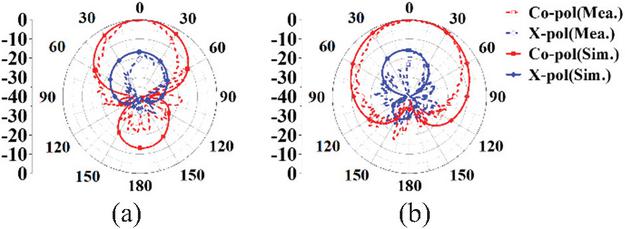
Figure 20 Radiation pattern at 5 GHz in XOZ plane (a) X-LP and (b) Y-LP.
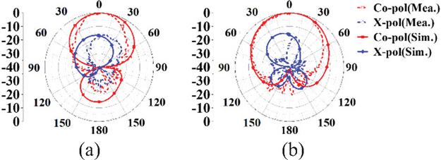
Figure 21 Radiation pattern at 5.4 GHz in XOZ plane (a) X-LP and (b) Y-LP.
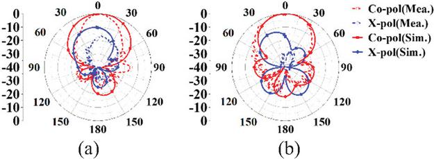
Figure 22 Radiation pattern at 5.9 GHz in XOZ plane (a) X-LP and (b) Y-LP.
Table 1 Comparison of the published dual-polarized antennas
| Ref. | AS | Size | Air Gap | Peak Gain (dBi) | Iso (dB) | BW (%) | Efficiency |
| [23] | 13 | 0.511.920.08 | With | 11.5 | 17 | 20.3 | 85% |
| [13] | Unit | 1.111.110.11 | With | 9.0 | 47 | 32.9 | NA |
| [12] | Unit | 1.31.30.13 | With | 9.1 | 28 | 25.1 | NA |
| [22] | 46 | 2.466.770.26 | With | 19.4 | 20 | 14.1 | NA |
| [6] | 212 | 1.261.260.315 | With | 5.9 | 22 | 17.1 | 91.7% |
| [19] | 12 | 0.80.40.006 | WO | NA | 19 | 0.86 | NA |
| [18] | 22 | 0.60.60.04 | WO | 6.2 | 27 | 5.2 | 80% |
| [4] | 22 | 3.052.020.14 | WO | 13 | 14 | 25.2 | NA |
| [7] | Unit | 1.151.150.28 | WO | 9.2 | 25 | 50.4 | 90% |
| This Work | 14 | 2.70.580.042 | WO | 12.5 | 20 | 17.4 | 75.4% |
| NA: Not applicable; WO: Without; Iso: Isolation; BW: Bandwidth; AS: Array scale. | |||||||
The radiation patterns in Figs. 20–22 show the measured and simulated results for X-LP and Y-LP at 5, 5.4, and 5.9 GHz in XOZ plane.
A comparison of the proposed antenna with existing designs is provided in Table 1. Compared with antennas that have an air gap in [6, 12, 13, 22, 23], the proposed antenna features a low profile, compact structure, and ease of fabrication. Compared with air-gap-free antennas in [18, 19], the proposed antenna exhibits a slightly higher profile but a significantly wider bandwidth. Moreover, its profile is much lower than that in [4, 7]. Its realized gain reaches 12.5 dBi, higher than that of the antennas in [6, 7, 12, 13, 18, 19, 23]. Overall, the proposed antenna demonstrates superior performance in isolation, structural compactness, and operating bandwidth.
4 CONCLUSION
In this paper, a dual-polarized antenna with low profile and high isolation is proposed. The polarization state of the antenna can be switched by selecting different feeding ports. The measurement results indicate that the antenna has a 10 dB impedance bandwidth of 4.975–5.925 GHz in different states, with a relative bandwidth of 17.4%. Arranging the antenna elements into a 14 array effectively improves the antenna gain. The peak gain of the array antenna reaches 12.5 dBi. The simulated and measured results are in good agreement, verifying the correctness of the design. Additionally, the proposed dual-polarized antenna benefits from low profile, compact size, low cost, and high isolation. It is suitable for various communication systems with space constraints, intelligent requirements, and anti-interference needs.
References
[1] J. Li, S.-J. Hao, Y.-G. Cui, and X. Chen, “A miniaturized wideband dual-polarized planar antenna based on multi resonance,” IEEE Antennas and Wireless Propagation Letters, vol. 21, no. 2, pp. 242–246, Feb. 2022.
[2] J.-Y. Yang, X.-H. Ding, W.-W. Yang, and J.-X. Chen, “Compact wideband dual-polarized antenna using shared dipoles loaded with partially coupled stubs,” IEEE Antennas and Wireless Propagation Letters, vol. 22, no. 12, pp. 2886–2890, Dec. 2023.
[3] Y. Zhang and Y. Zhang, “Dual-band dual-polarized antenna using a simple radiation restoration and decoupling structure,” IEEE Antennas and Wireless Propagation Letters, vol. 22, no. 4, pp. 709–713, Apr. 2023.
[4] H. C. Ye, C. Mao, L. L. Dai, and X. Y. Zhang, “Dual-band dual-polarized antenna and array with enhanced bandwidth for 5G millimeter-wave applications,” IEEE Antennas and Wireless Propagation Letters, vol. 24, no. 7, pp. 1829–1833, July 2025.
[5] R. Wu, C.-R. Li, and F.-C. Chen, “Tri-band dual-polarized shared-aperture antenna array for base station applications,” IEEE Antennas and Wireless Propagation Letters, vol. 24, no. 9, pp. 3213–3217, Sep. 2025.
[6] H. Yuan and F.-C. Chen, “A mixed decoupling scheme based on AMC and ADS for dual-polarized antenna array,” IEEE Transactions on Antennas and Propagation, vol. 71, no. 7, pp. 6150–6155, July 2023.
[7] J. Qi, J. Pan, Y. Li, and G.-L. Huang, “A wideband base station antenna loaded with bow-tie-like parasitic elements,” Applied Computational Electromagnetics Society (ACES) Journal, vol. 37, no. 08, pp. 893–900, Aug. 2022.
[8] B. P. Smyth and A. K. Iyer, “Low-profile uniplanar dual-band and dual-polarized microstrip patch antenna using embedded MTM-EBGs,” IEEE Transactions on Antennas and Propagation, vol. 69, no. 7, pp. 3645–3653, July 2021.
[9] C. Zhou, J. Sun, W.-W. Yang, M. Li, and H. Wong, “A wideband low-profile dual-polarized hybrid antenna using two different modes,” IEEE Antennas and Wireless Propagation Letters, vol. 22, no. 1, pp. 114–118, Jan. 2023.
[10] J. Liu, H. Liu, X. Dou, Y. Tang, C. Zhang, L. Wang, R. Tang, and Y. Yin, “A low profile, dual-band, dual-polarized patch antenna with antenna-filter functions and its application in MIMO systems,” IEEE Access, vol. 9, pp. 101164–101171, 2021.
[11] X. Zhang, D. Zhou, Y. Li, K. Wei, and Z. Zhang, “A simple dual-polarized patch antenna array for Wi-Fi 6/6E application,” IEEE Transactions on Antennas and Propagation, vol. 70, no. 11, pp. 11143–11148, Nov. 2022.
[12] M. Ciydem, “A low-profile dual-polarized antenna with high isolation and high front-to-back ratio for 5G base stations,” Applied Computational Electromagnetics Society (ACES) Journal, vol. 36, no. 09, pp. 1229–1236, Nov. 2021.
[13] M. Ciydem and E. A. Miran, “A low-profile hybrid-fed dual-polarized antenna with high isolation and high cross-polar discrimination,” Applied Computational Electromagnetics Society (ACES) Journal, vol. 36, no. 09, pp. 1164–1172, Nov. 2021.
[14] S. Aminu, N. Yan, Y. Luo, K. Ma, I. Bello, and E. N. Moro, “High isolation dual-polarized SISL antenna with out-of-band rejection improvement using artificial magnetic conductor,” IEEE Antennas and Wireless Propagation Letters, vol. 23, no. 11, pp. 3882–3886, Nov. 2024.
[15] Y. Xu, R. Li, Z.-X. Liu, Y. Hu, C. Wang, and Y. Liu, “Dual-polarized crossed-dipole base station antenna array with high-isolation and wide-angle scanning,” IEEE Transactions on Antennas and Propagation, vol. 72, no. 11, pp. 8394–8403, Nov. 2024.
[16] B. Qian, A. Zhang, X. Chen, and A. A. Kishk, “Ultralow-profile decoupling patch structure for E-plane microstrip antenna arrays,” IEEE Antennas and Wireless Propagation Letters, vol. 24, no. 10, pp. 3799–3803, Oct. 2025.
[17] B. Chen, A. Zhang, and X. Chen, “Decoupling of planar circularly polarized patch array by ADS and parasitic structure,” IEEE Antennas and Wireless Propagation Letters, vol. 24, no. 9, pp. 2979–2983, Sep. 2025.
[18] C. Guo, Y. Jia, Y. Wang, and H. Zhai, “A dual-polarized antenna array with high port isolation through TM03/04 modes cancellation,” IEEE Antennas and Wireless Propagation Letters, vol. 22, no. 8, pp. 1987–1991, Aug. 2023.
[19] M. Li, T. Yang, X.-X. Yang, D. Zeng, and Z. Yi, “A defected ground structure for TE and TM coupling reduction of dual-polarized antenna array,” IEEE Antennas and Wireless Propagation Letters, vol. 23, no. 9, pp. 2648–2652, Sep. 2024.
[20] Y. Wang, X. Wang, J. Wang, and R. Shao, “Dual-band highly isolated eight-element MIMO antenna for 5G mobile phone,” Applied Computational Electromagnetics Society (ACES) Journal, vol. 37, no. 05, pp. 588-596, May 2022.
[21] T. Yoon, U. Park, and J. Oh, “Band-stop behavior vertically extended ground isolator based on transmission line theory for IBFD TRx decoupling applications,” IEEE Transactions on Microwave Theory and Techniques, vol. 72, no. 2, pp. 1405–1415, Feb. 2024.
[22] F.-F. Fan, P.-P. Ma, and Q.-L. Chen, “Wide-angle scanning and high isolation dual-polarized base station antennas for sub-6 GHz applications,” Applied Computational Electromagnetics Society (ACES) Journal, vol. 39, no. 02, pp. 149–155, Feb. 2024.
[23] T.-Y. Yan, X.-H. Ding, J.-Y. Yang, and J.-X. Chen, “A low-cost compact dual-polarized patch antenna array for 5G massive MIMO base station,” IEEE Antennas and Wireless Propagation Letters, vol. 23, no. 4, pp. 1381–1385, Apr. 2024.
[24] Rachmansyah, A. Irianto, and A. Mutiara, “Designing and manufacturing microstrip antenna for wireless communication at 2.4 GHz,” International Journal of Computer and Electrical Engineering, vol. 3, no. 5, Oct. 2011.
Biographies

Yue-Chen Liu was born in Handan, Hebei, China, in 2000. She received the B.E. degree in Electronic Information Engineering from Xi’an University of Posts & Telecommunications, Xi’an, Shaanxi, in 2018. She is currently pursuing the M.E. degree in electronic science and technology in Qingdao University, Qingdao, Shandong. Her research interest is antennas.

Xiaoyun Qu was born in Yantai City, Shandong Province, China, in 1974. She received the B.S. in applied mathematics from Yantai University, in 1996, M.S. degree in electromagnetic fields and microwave technology from Nanjing Electronics research Center, Nanjing, Jiangsu Province, in 1990. She is with Shandong Institute of Space Electronic Technology, Yantai, as a Senior Engineer. Her research interest is antenna design.

Cheng Ju received the Ph.D. degree from Beijing University of Posts and Telecommunications in 2015. He joined the School of Electronic Information at Qingdao University in 2017 as a lecturer. He is mainly engaged in researching DSP algorithms for space laser communication systems and FPGA implementation of DSP algorithms.

Wei-Hua Zong was born in Penglai City, Shandong Province, China, in 1975. She received the B.S. in applied mathematics from Yantai University, in 1997, M.S. degree in electromagnetic fields and microwave technology from Nanjing Electronics research Center, Nanjing, Jiangsu Province, in 2000, and the Ph.D. degree in electromagnetic fields and microwave technology from Xidian University, Xian, Shanxi Province, in 2004. In 2004, she joined Qingdao University, Qingdao, Shandong Province, as a lecturer. Since 2005, she has been an Associate Professor in Qingdao University. From February to August 2010, she was a Visiting Scholar Assistant with Electrical and Computation Engineering Department, National University of Singapore. Her research interests include antenna design and electromagnetic material measurement.
ACES JOURNAL, Vol. 41, No. 2, 162–169
DOI: 10.13052/2026.ACES.J.410207
© 2026 River Publishers