Modeling of Thin Shielding Layer Based on Unstructured Grid Vector Finite Element Method and Analysis of its Effect on SQUID TEM Observation Signal
Binyuan Ma1, Nansong Chang1, Yanju Ji1, 2, Xuejiao Zhao1, 2, and Hui Luan1, 2
1College of Instrumentation and Electrical Engineering
Jilin University, Changchun 130000, China
maby20@mails.jlu.edu.cn, changns24@mails.jlu.edu.cn, jiyj@jlu.edu.cn, zhaoxuejiao@jlu.edu.cn, luanhui@jlu.edu.cn
2Key Laboratory of Geophysical Exploration Equipment Ministry of Education
Jilin University, Changchun 130000, China
Submitted On: October 13, 2025; Accepted On: March 24, 2026
Abstract
Superconducting Quantum Interference Devices Time-Domain Electromagnetic Method (SQUID TEM) is currently the most accurate electromagnetic detection technology used in geophysics. However, SQUID is highly susceptible to electromagnetic interference in outdoor spaces, so it needs to work continuously and stably in a Dewar bucket wrapped with a metal shielding material. Therefore, the influence of the metal shielding thin layer on the observation signal cannot be ignored. We propose a vector finite element method based on unstructured grids to spatially model the sleeve formed by the metal shielding thin layer wrapped around the SQUID and analyze the influence of the metal shielding sleeve on the SQUID TEM observation signal. Firstly, we derive the governing equations from Maxwell’s equations. Secondly, the Galerkin method is used for finite element discretization of the control equations, and unstructured mesh discretization is applied to the metal shielding sleeve and other computational areas. By solving the interpolation basis functions of tetrahedral vector elements, the local equations of each element are obtained and combined into a global large sparse matrix. Finally, the direct solution method is used to calculate the electromagnetic response at the observation points inside the metal shielding sleeve. The effectiveness and universality of the proposed method are verified through numerical simulations. Furthermore, through field experiments in the Da Hinggan Ling area, the necessity of metal shielding sleeves in field experiments and the reliability of the calculation results proposed have been demonstrated.
Index Terms: SQUID TEM, thin shielding layer modeling, unstructured tetrahedral mesh, vector finite element method.
I. INTRODUCTION
Superconducting Quantum Interference Devices Time-Domain Electromagnetic Method (SQUID TEM) is currently the most accurate electromagnetic detection method used for geophysical field surveys, with unique advantages in weak magnetic signal observation and polymetallic mineral exploration [1, 2, 3, 4, 5, 6]. Due to the complex physical properties and parameter information of polymetallic ores in nature, most of them exhibit low resistivity or polarization characteristics in timedomain electromagnetic detection [7, 8, 9, 10]. The physical properties of these ores are reflected in the sign reversal in the magnetic field signals observed by SQUID TEM systems [11, 12]. In actual field exploration, the SQUID sensor placed in a Dewar vessel containing liquid nitrogen must be wrapped with a certain thickness of metal material as a shielding sleeve outside the Dewar vessel to achieve spatial electromagnetic interference shielding, so as to achieve long-term stable operation of the system [13, 14, 15]. The effective signals observed by SQUID sensors, especially the polarized signals containing deep mineral layer information, are usually on the order of pT or even fT , and the weak electromagnetic signals that characterize deep information are usually in the late low-frequency range. Therefore, it is very necessary to study the influence of metal shielding sleeves on the observation signal in the SQUID TEM detection.
In order to achieve mesh modeling of curved surfaces and numerical simulation of spatial electromagnetic response in geophysical methods, scholars have conducted extensive research on mesh partitioning methods and numerical simulation methods. He et al. proposed a method that combines curved hexahedral mesh and regular hexahedral mesh to solve the problem of the influence of the surface topography and gradient approximation on inversion results [16]. Cao et al. used unstructured tetrahedral mesh to simulate complex underground structures and rugged terrain and successfully achieved forward modeling and inversion calculation of the Z-axis tipper electromagnetic (ZTEM) using the finite element method [17]. Zhu et al. achieved numerical simulation of the electromagnetic response of complex underground structures in electromagnetic (EM) detection by introducing a spectral element method based on unstructured tetrahedral grids [18]. Key used unstructured triangular or quadrilateral grids to simulate geometric shapes that conform to actual measurements, and then accurately calculated electromagnetic responses through adaptive finite element method [19]. Li et al. simulated the geometric shapes of complex models based on unstructured tetrahedral grids and solved the marine controlledsource electromagnetic (CSEM) response using adaptive finite element method [20]. Zhou et al. used an unstructured tetrahedral mesh to accurately discretize the true complex shape of unexploded bombs and combined it with the finite element method to accurately simulate the time-domain electromagnetic response of unexploded bombs in TEM measurements [21]. Rong et al. proposed an arbitrary anisotropic inversion method based on unstructured tetrahedral mesh discretization, which can adapt well to complex structures such as Earth’s terrain and coastline, and ultimately produce inversion results that conform to actual geological data [22]. In summary, whether obtaining accurate numerical simulation results through forward modeling or achieving outcomes more consistent with actual geological data via inverse modelling, it is necessary to take into account the geometric modeling of the actual survey situation. Furthermore, realistic geometric modeling and appropriate numerical simulation methods are key to accurately obtaining electromagnetic responses. Therefore, it is very important to accurately calculate the electromagnetic response at the observation point of the SQUID TEM system under the condition of a thin shielding sleeve.
At present, scholars have a certain theoretical research basis for the numerical calculation of spatial electromagnetic field distribution with thin layers. Liu et al. used the finite difference method and nonuniform mesh partitioning technique to study the influence of metal thin layers on the detection of effective anomalous signals in TEM detection. The results showed that metal thin layers would reduce the detection sensitivity of TEM and weak the electromagnetic response of low resistivity anomalous targets [23]. Zhou et al. proposed an enriched finite element method to numerically simulate the electromagnetic response of magneto electro elastic composite materials excited by external electric or magnetic fields and improved the solution accuracy through grid refinement [24]. Etse et al. proposed a method that combined homogenization of multi-layer shielding layers with the second-order AMSL method to accurately model thin layers of metal composite materials and applied it to magnetic shielding [25]. Gao et al. used the finite element method to model and calculate multi-layer metal thin shell structures for magnetic shielding, quantitatively analyze their electromagnetic characteristics, and provided a theoretical basis for precision measurement research of low-noise magnetic shielding [26]. Korkotadze et al. calculated the near-field shielding effect of two-layer and three-layer thin plates based on vector wave equations and boundary conditions, which can predict the shielding effect of multi-layer plates under known material properties and help determine the optimal thickness of the shielding layer [27]. In addition, some scholars used commercial software based on finite element method for numerical simulation and calculation and made significant progress in various fields such as simulating electromagnetic interference of shielded cables [28], simulating the effects of return stroke parameters and soil water content on EMF characteristics [29], and simulating the influence of augmented rail geometry on rail gun design parameters [30]. The availability of finite element commercial software is only for the problems that are suitable for the software to solve, and there may be issues with low computing efficiency [31]. It can be seen that the finite element method and its extensions are one of the flexible and efficient important techniques among many methods in different fields of studying electromagnetic field related problems [24, 26, 32, 33, 34]. However, most scholars’ research is limited to the physical modeling of shielding thin-layer materials and the analysis of shielding performance, and the computational research area is mostly within the calculation area near the thin layer, which has not yet involved the problem of low computational efficiency or even non-convergence that may occur due to a large calculation area. Due to the fact that SQUID TEM long wire sources are usually several kilometers long, and the distribution of underground ore bodies detected is often tens of meters or even thousands of meters, it is necessary to study how to calculate the influence of small-sized metal shielding sleeves on weak signals observed inside the cylinder in large-scale space.
We propose a vector finite element method based on unstructured grids for modeling thin metal shielding sleeves and analyze their impact on SQUID TEM observation signals. In the first place, the thin metal shielding sleeve is finely modeled using the unstructured tetrahedral mesh, and the entire calculation area is discretized reasonably. The control equations are derived from the Maxwell equations, and the Galerkin method is used for finite element discretization of the control equations. Then, the metal shielding sleeve and other calculation areas are discretized using the unstructured mesh. Secondly, by solving the interpolation basis functions of tetrahedral vector elements, the local equations of each element are obtained, and the local equations are combined into a global large sparse matrix. Finally, the direct solution method is used to calculate the electromagnetic response at the observation point with a metal shielding sleeve. To demonstrate the effectiveness of our proposed method, we have designed three typical models and have calculated the effects of metal shielding sleeves on the SQUID TEM observation signals under different models. In addition, we have also verified the correctness of the proposed method’s calculation conclusions through field experiments in the Da Hinggan Ling area.
II. THEORY
A. Vector finite element method
The first and second equations of Maxwell’s system of equations:
| (1) | |
| (2) |
The dual curl equation of the electric field can be derived:
| (3) |
In order to avoid the problem of non-singularity caused by the source term during the solving process, the total field is written in the form of the superposition of the background field and the quadratic field, that is
| (4) |
Therefore, the control equation can be written as:
| (5) |
For the convenience of subsequent solving
| (6) | |
| (7) |
Substituting equations (6) and (7) into equation (5) and organizing them, we can obtain:
| (8) |
The Galerkin method [35] is used to discretize equation (8), and the residual expression of the control equation is:
| (9) |
where is the approximate solution of the quadratic field to be solved.
Let the weight function be , and let the residual of all units in the calculation area and the inner product of the weight function be zero to seek the optimal solution, that is:
| (10) |
By substituting the residual equation into equation (10), we can obtain:
| (11) |
By using Green’s formula to expand the first term of equation (11), we can obtain:
| (12) |
That is:
| (13) | |
| (14) |
where is the unit normal vector on the surface . The electric field within each unit can be written as:
| (15) |
where is the vector basis function and is the number of each edge of the tetrahedral element.
Based on the Galerkin method, the weight function is taken as the vector basis function and further integrated within the vector finite element calculation area:
| (16) |
Discretize each tetrahedral element to obtain the equation in the discrete form of each tetrahedron:
| (17) |
where and represent the labels of rows and columns, is the left-hand term matrix of the equation, and is the right-hand term matrix of the equation.
Combine all equations in equation (17) into a global equation and represent it as a sparse matrix:
| (18) |
By using the direct solution method to solve equation (18), the electric field matrix can be obtained, and then the magnetic field matrix can be solved from equation (1). Finally, the time-domain magnetic field response can be obtained through frequency-time transformation [36].
B. Unstructured tetrahedral mesh and vector interpolation basis function solution
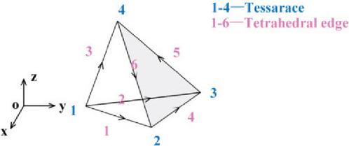
Figure 1 Schematic diagram of the unstructured tetrahedral unit.
In any tetrahedral element, as shown in Fig. 1, the expression of the basis function to be solved can be set as:
| (19) |
where is tetrahedral unit numbers and , and are undetermined coefficients.
By substituting equation (19) into each vertex, we can obtain:
| (20) | |
| (21) | |
| (22) | |
| (23) |
where , and correspond to the coordinates of vertices , and 4, respectively.
By solving equations (20)–(23) simultaneously, we can obtain:
| (24) | ||
| (25) | ||
| (26) | ||
| (27) | ||
| (28) | ||
| (29) | ||
| (30) | ||
| (31) |
where represents the volume of tetrahedral units:
| (32) |
According to the coordinates of the four vertices of the tetrahedral element, each undetermined coefficient in the basis function equation (19) to be solved can be calculated separately, that is:
Substituting the above coefficients into the expression of the basis function to be solved, the basis function can be written as:
| (33) |
where is the interpolation basis function, whose expression is:
| (34) |
Therefore, the tetrahedral vector basis function can be expressed as:
| (35) |
It satisfies the condition of zero divergence, and the curl expression is:
| (36) |
That is:
| (37) |
where , and are the unit vectors of direction , , and , respectively.
III. NUMERICAL RESULTS
In order to investigate the effect of the metal shielding layer wrapped around the Dewar vessel with SQUID on the measurement of secondary field signals in the SQUID TEM observation experiments, we have first modeled and meshed the SQUID TEM experimental system based on the actual situation. Then, we have studied the influence of the shielding layer on the observed signals when the measurement background is a uniform ground. In this section, we compare the proposed method with the calculation results of the traditional finite element method to verify the accuracy and correctness of our proposed method.
Subsequently, we introduce the low resistivity anomalous body into the uniform ground model and study the impact of the shielding layer on the observation signal by calculating the electromagnetic response curve with and without the shielding layer. In this section, we study and discuss the influence of the thickness of the metal shielding layer on the magnetic field signal.
Finally, to demonstrate the universality of our proposed method, we introduce the polarized anomalous body into the uniform ground model and analyze the influence of the shielding layer on the electromagnetic response of the SQUID TEM system for detecting polarized anomalies. In addition, we discuss and compare the effect of the shielding layer on the electromagnetic response of SQUID TEM system detecting polarization anomalies under different polarization parameters.
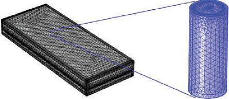
Figure 2 SQUID TEM observation system and modeling of thin shielding layer.
We have constructed a calculation area of , as shown in Fig. 2, with an air layer and a uniform ground, respectively. The length of the long wire source is 1 km, and the current is 20 A. The long wire source is placed in the large geological formation along the x-axis direction, with a horizontal distance of 300 m from the center point of the source to the center point of the metal shielding cylinder. Considering that the commonly used shielding material for SQUID TEM systems in actual field measurements is aluminum foil [6, 12, 37, 38], we have constructed a cylindrical shielding sleeve with an outer diameter of 30 cm and an inner diameter of 24 cm. The outer shielding material is aluminum and the conductivity is . In field experiments, the aluminum foil usually wrapped around the cylinder is more than ten layers, so the thickness of the aluminum metal shielding layer is designed to be .
A. Influence of a thin shielding layer on the SQUID TEM signal under a uniform half space model
On the basis of the above modeling, the conductivity of a uniform ground is set to , and the horizontal distance between the center of the shielding bucket and the long wire source is 300 m. The electromagnetic response of the observation point at a distance of 10 cm from the ground surface inside the shielding bucket and the electromagnetic response at the same observation point without the shielding bucket are calculated separately. The calculation results are shown in Fig. 3.
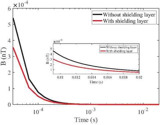
Figure 3 Influence of a thin shielding layer on the SQUID TEM signal under a uniform half-space model.
The calculation results in Fig. 3 indicate that when a shielding bucket is present, the magnetic field response inside the shielding bucket is always smaller than that without the shielding bucket, indicating that the shielding bucket has a certain weakening effect on the magnetic field signal observed in the SQUID TEM system. It can be clearly seen that the presence of the shielding bucket has a stronger weakening effect on early signals.
In order to verify the correctness and effectiveness of the proposed method, taking the uniform geodetic model as an example, we have set the same model parameters and compared the calculation results of the traditional finite element method with those of the method proposed in Fig. 3. The comparison results are shown in Fig. 4.
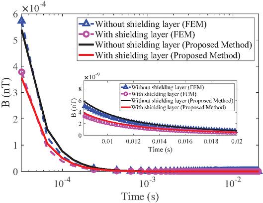
Figure 4 Comparison of calculation results between the unstructured grid vector finite element method and the finite element method.
From the calculation results in Fig. 4, it can be seen that the proposed method is consistent with the traditional finite element method. Therefore, the correctness and effectiveness of the numerical simulation method proposed have been verified.
B. Influence of a thin shielding layer on the SQUID TEM signal under a low resistivity anomalous body model
On the basis of the above modeling, a uniform earth conductivity of is set, and a low resistivity anomalous body of is set at 500 m below the surface with a conductivity of . The center of the shielding cylinder with a thin layer of metal aluminum is set to coincide with the center of the anomalous body in the vertical direction. The electromagnetic response at the observation point 10 cm away from the surface inside the shielding cylinder and the electromagnetic response at the same observation point without a shielding cylinder are calculated separately. The calculation results are shown in Fig. 5.
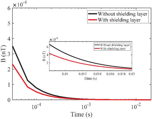
Figure 5 Influence of a thin shielding layer on the SQUID TEM signal under a low resistivity anomaly model.
The calculation results in Fig. 5 indicate that, in addition to the attenuation effect on the SQUID TEM observation signal when the shielding bucket is present, compared with the magnetic field response curve calculated for the uniform half-space model in Fig. 3, the magnetic field amplitude of the corresponding curve in Fig. 5 is significantly smaller due to the presence of the low resistivity anomalous body. Therefore, the introduction of shielding bucket modeling will not affect the basic characteristics of TEM observation signals under low resistivity anomaly models, that is, the magnetic field signal inside the shielding bucket can still be used to display the relative magnitude of the resistivity of the anomalous body.
Compared with the magnetic field response without the shielding bucket (black curve in Fig. 5), the TEM magnetic field response curve observed inside the shielding bucket will first decay to the resolution threshold of the SQUID sensor, especially for late time channels. Due to the deeper geological exploration depth corresponding to the late time channel in TEM detection, the signal attenuation caused by the presence of the shielding bucket would ideally result in a shallower maximum effective depth for future data interpretation and inversion.
In order to further study and analyze the influence of the thickness of the metal shielding thin layer on the magnetic field signal observed by SQUID TEM, based on the low resistivity anomalous body model mentioned above, we assume that the thickness of a single layer of aluminum foil is , and calculate the electromagnetic response of the observation point position 10 cm away from the ground surface in the cylinder under shielding layers , and 50, respectively. That is, the corresponding shielding layer thickness and , and the calculation results are shown in Fig. 6.
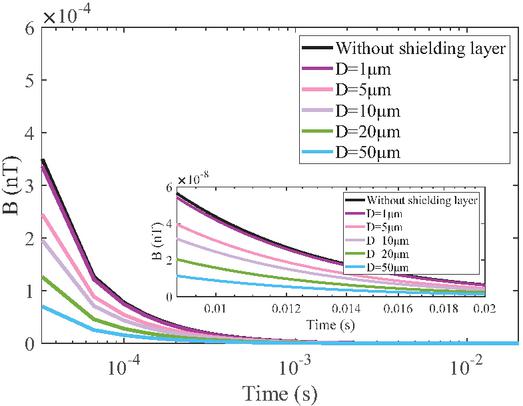
Figure 6 Influence of a thin shielding layer thickness on the SQUID TEM signal under a low resistivity anomaly model.
From the calculation results in Fig. 6, it can be seen that compared with the magnetic field curve of the unshielded thin layer, when the shielding layer is , both curves almost overlap in both the early and late stages, and the shielding layer has little effect on the magnetic field response. As the thickness of the shielding layer increases, the early magnetic field values significantly decrease, indicating that the thicker the shielding layer, the better the shielding effect. However, if the shielding layer is too thick, the attenuation curve will become flatter (blue curve in Fig. 6), and it will no longer be able to effectively distinguish whether low resistivity anomalies exist. Therefore, the thickness of the shielding thin layer is not necessarily the thicker the better. There is a suitable thickness that could shield the SQUID from external electromagnetic interference while still allowing the abnormal body information carried by the attenuation curve to be clearly distinguished.
C. The influence of a thin shielding layer on the SQUID TEM signal under a polarized anomalous body model
On the basis of the above modeling, the conductivity of a uniform ground is set to . Based on typical parameters of common polymetallic ores, a polarization anomaly body is set 500 m below the surface. The Cole-Cole model parameters of the anomaly body are zero frequency conductivity of , polarization rate of 0.5, time constant of , and dispersion coefficient of 0.5. We set the center of the shielding cylinder with a thin layer of metal aluminum to coincide with the center of the anomalous body in the vertical direction. Then, We calculate the electromagnetic response at the observation point 10 cm away from the ground surface inside the shielding cylinder and the electromagnetic response at the same observation point without the shielding cylinder. The calculation results are shown in Fig. 7.
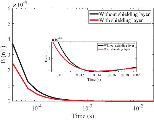
Figure 7 Influence of a thin shielding layer on the SQUID TEM signal under a polarized anomaly model.
The calculation results in Fig. 7 indicate that, in addition to the attenuation effect on the SQUID TEM observation signal when the shielding bucket is present, there are two intersection points in the magnetic field response curves of Fig. 7 with and without the shielding bucket compared to Fig. 3. From the perspective of the electromagnetic field, this indicates that both positive and negative response parts are attenuated by the shielding bucket, rather than the polarization signal being larger when the shielding bucket is present than when it is absent. Therefore, in actual detection, the presence of a shielding bucket has a significant impact on the polarization information of rock and ore carried by the polarization signal, so the influence of a metal thin layer shielding bucket cannot be ignored.
In order to further analyze the influence of the presence of metal shielding thin layers on the electromagnetic response of polarized anomalous bodies, we have calculated the magnetic field curves of the anomalous body with different polarizations at the shielding layer thickness of , and we also have studied the differences between them. We have set polarizations of , and , respectively, and have studied the influence of metal shielding thin layers on the electromagnetic response of anomalous bodies with different degrees of polarization. The calculation results are shown in Figs. 8 and 9, where Fig. 9 is a locally enlarged view of the polarization response characteristic segment of the curve in Fig. 8.
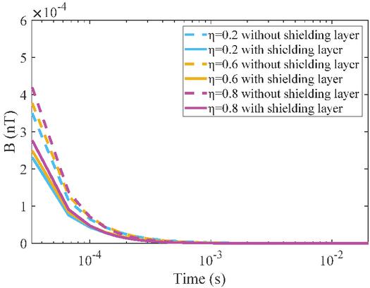
Figure 8 Magnetic field response curves of anomalous bodies with different polarizations under the same shielding thin layer condition.
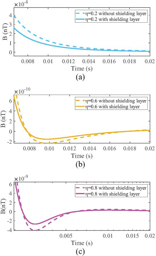
Figure 9 Magnetic field curves of polarization response amplification segments of anomalous bodies with different polarizations under the same shielding thin layer conditions: (a) , (b) , (c) .
From Fig. 8, it can be seen that the higher the polarizability of the anomalous body, the greater the attenuation effect of the shielding thin layer on the early signals observed by SQUID TEM. Furthermore, Fig. 9 is a partial enlargement of the polarization response characteristic segments of the curve in Fig. 8. From Fig. 9 (a), we can see that the weak polarization signal will no longer exhibit negative response in the late stage, and the introduction of the shielding layer will not cause false amplitude response in the curve that originally had no negative response. The phenomenon consistent with Fig. 7 is observed in Figs. 9 (b) and (c). Comparing Figs. 9 (b) and (c), it can be seen that the introduction of a shielding thin layer only reduces the absolute value of the maximum negative value representing the polarization response characteristic and does not completely eliminate the polarization response that should have existed. Therefore, the method proposed in this paper can be used to accurately model the shielding thin layer and analyze its impact on the SQUID TEM observation signal, providing reliable theoretical guidance for practical detection.
In the above three typical geoelectric models, the introduction of the shielding layer has a certain degree of impact on the magnetic field signal observed by SQUID TEM, which is reflected in the characteristics of the electromagnetic response curve. Table 1 summarizes the magnetic field characteristics with and without the shielding bucket.
The summary in Table 1 indicates that the presence of the shielding bucket has different effects on the SQUID TEM observation signal depending on the geological model. The more parameters in the geoelectric model, the more complex it becomes, and the more diverse the impact of the shielding bucket on the SQUID TEM observation signal. This highlights the necessity of precise calculation and analysis of the influence of the thin shielding layer on SQUID TEM observation signal. Furthermore, the method proposed also lays a theoretical foundation for future research on how to accurately interpret and invert data based on the impact of the shielding bucket.
Table 1 Summary of the magnetic field characteristics with and without the shielding layer
| Model | Characterization | Result |
| Uniform Half Space | ➀ The magnetic field inside the shielding bucket is always smaller than that without the shielding bucket. | Fig. 3 |
| ➁ The shielding bucket has a certain weakening effect on the magnetic field signal. | ||
| Low Resistivity Anomalous Body Model | ➀ The magnetic field signal inside the shielding bucket could still display the relative magnitude of the resistivity of the anomalous body. | Fig. 5 |
| ➁ The signal attenuation caused by the shielding bucket would result in a shallower maximum effective depth for later data interpretation | ||
| Polarized Anomalous Body Model | ➀ The higher the polarizability of the anomalous body, the greater the attenuation effect of the shielding thin layer on the early signal. | Fig. 7 Fig. 8 Fig. 9 |
| ➁ The shielding thin layer only reduces the absolute value of the maximum negative value representing the polarization response characteristic. |
IV. FIELD SURVEY EXPERIMENT AND RESULTS
To further verify the effectiveness of the proposed method and the reliability of the calculation conclusions, a long wire source SQUID TEM field experiment has been conducted in the Da Hinggan Ling area of Heilongjiang Province, China. The detection area is located on the east side of the main peak basin in the northern section of the Da Hinggan Ling, with an average elevation of 1300 m and a relative elevation difference of 300–450 m. The main metallic minerals present are lead zinc polymetallic deposits with polarization effects. The surrounding rocks mainly include marble and skarn, and the shallow surface mainly consists of gravel and clay.
The instruments used in the experiment are shown in Fig. 10. The metal material wrapped around the acrylic cylinder is aluminum foil. The transmitter generates bipolar trapezoidal waves with a period of 80 ms to excite the underground target ore body and generate electromagnetic response. The SQUID TEM system has a resolution of 100 fT and a sampling rate of 30 kHz for the receiver.
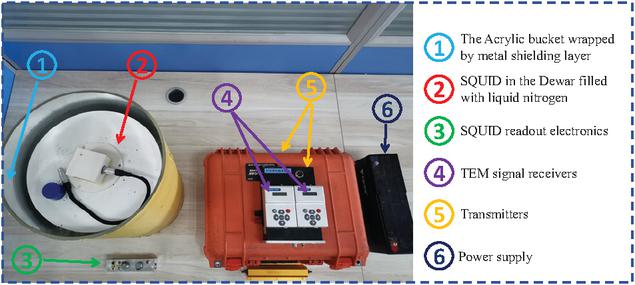
Figure 10 SQUID TEM experimental instruments.
The actual location and layout of the measuring points in the survey area are shown in Fig. 11. The emission source is 1.7 km long and emits a current of 18 A. A total of 12 measurement points are measured from the near source to the far source, with a distance of 50 m between each point. Due to the serious influence of high-power power supply vehicles and spatial electromagnetic interference, the SQUID sensor without the shielding bucket could only work intermittently at the two furthest points from the emission source, but there is still a problem of frequent loss of lock and unstable measurement [39]. Therefore, very little effective data can be collected, which also indicates the necessity and importance of metal shielding layer. Moreover, we have taken the measurement results of the observation point furthest from the emission source as the example to verify the reliability of the method proposed in this paper and its conclusions. The measurement results of the furthest point and the typical measurement curves caused by SQUID unlocking due to electromagnetic interference are shown in Fig. 12.
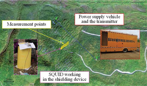
Figure 11 Layout of SQUID TEM field experiment site in the Da Hinggan Ling area.
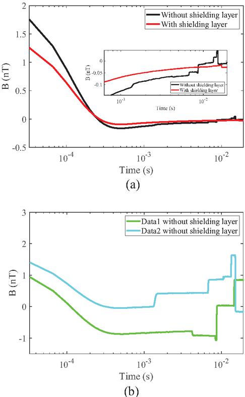
Figure 12 Measured SQUID TEM magnetic field signals: (a) comparison of electromagnetic response with and without the shielding cylinder at the furthest point and (b) typical unlocked magnetic field curves.
As shown in Fig. 12 (a), the influence of the shielding bucket on the experimental measurement results is almost identical to the trend obtained from the numerical simulation method proposed. Due to the fact that the actual earth is not uniform and the actual parameters of the geological environment are very complex, the amplitude and attenuation rate of the magnetic field response curves obtained from experimental measurements are not exactly the same as those obtained from numerical simulations. However, the trend of the shielding bucket’s influence on the SQUID TEM measurement results reflected by the two is almost alike.
Furthermore, due to the significant impact of external electromagnetic interference on the SQUID sensor when measuring without the shielding bucket, the interference on the later measurement curve is extremely severe, as shown in the enlarged part of Fig. 12 (a). Although we have conducted multiple measurements in the field, the SQUID sensor itself is still severely affected by surrounding electromagnetic interference in the unshielded environment, which leads to irregular jumps in the late-stage signal, resulting in a small segment of the signal intersecting with the signal measured in a shielded environment that should not have occurred. Therefore, the rock mineral resistivity information carried by the later signal is unreliable, which once again confirms the importance of measurement inside the shielding bucket.
Figure 12 (b) shows the magnetic field curves that can be measured without the shielding cylinder, however, most of the time in the experiment, the system cannot be locked for normal measurements. This also indicates that it is necessary to study the influence of metal shielding thin layers on SQUID TEM observation signals through the method proposed in this manuscript, which lays a theoretical foundation for further research on how to eliminate the influence of shielding thin layers on magnetic field response and improve detection resolution in the future.
V. CONCLUSION
We propose a vector finite element method based on unstructured grids. The Galerkin method is used to solve the vector basis functions, and the unstructured grids are discretized for the shielding thin layer and other calculation areas. Finally, the electromagnetic response calculation of the area with shielding thin layer is achieved. By calculating the effect of shielding thin layers on the SQUID TEM observation signals under different models, the influence of the presence of metal thin layer shielding sleeves on the SQUID TEM signals under three common model conditions has been summarized. Furthermore, the field detection experiments have been designed and conducted to verify the effectiveness and reliability of the proposed method in this paper. The method proposed can accurately calculate and analyze the impact of thin shielding layers on the SQUID TEM observation signals, providing theoretical basis and research foundation for the subsequent research on how to eliminate the influence of shielding thin layers and accurately invert observation data.
ACKNOWLEDGMENT
This work was supported by National Science and Technology Project of China No. 2024ZD1002605 and Key Laboratory of Geophysical Exploration Equipment, Ministry of Education (Jilin University) under Grant 20240104.
REFERENCES
[1] R. Stolz, M. Schiffler, M. Becken, A. Thiede, M. Schneider, G. Chubak, P. Marsden, A. B. Bergshjorth, M. Schaefer, and O. Terblanche, “SQUIDs for magnetic and electromagnetic methods in mineral exploration,” Mineral Economics, vol. 35, pp. 467–494, 2022.
[2] R. Stolz, M. Schmelz, V. Zakosarenko, C. Foley, K. Tanabe, X. Xie, and R. L. Fagaly, “Superconducting sensors and methods in geophysical applications,” Superconductor Science and Technology, vol. 34, pp. 1–33, 2021.
[3] E. Arai, “State-of-the-art geophysics for metal exploration,” Resource Geology, vol. 71, pp. 470–491, 2021.
[4] H. Ren, Y. Wang, C. Chen, G. Fu, L. Qiu, L. Guo, C. Xie, Y. He, H. Sun, and J. Teng, “Underground laboratories Deep underground observation Scientific questions—Insights from observations of multi-physic fields in deep underground labs,” Science China Earth Sciences, vol. 68, pp. 343–362, 2025.
[5] J. Wu, Q. Zhi, X. Deng, X. Wang, X. Chen, Y. Zhao, and Y. Huang, “Deep gold exploration with SQUID TEM in the Qingchengzi Orefield, Eastern Liaoning, Northeast China,” Minerals, vol. 12, p. 102, 2022.
[6] I. Mohanty, R. Nagendran, L. Bisht, A. V. T. Arasu, R. Baskaran, B. V. L. Kumar, and M. B. Verma, “Development of SQUID based TDEM system and its utilization for field survey at Tumallapalle, Andhra Pradesh, India,” Journal of Applied Geophysics, vol. 204, p. 104746, 2022.
[7] A. Revil, D. Mao, Z. Shao, M. F. Sleevi, and D. Wang, “Induced polarization response of porous media with metallic particles—Part 6: The case of metals and semimetals,” Geophysics, vol. 82, pp. E97–E110, 2017.
[8] D. J. Marshall and T. R. Madden, “Induced polarization, a study of its causes,” Geophysics, vol. 24, pp. 790–816, 1959.
[9] G. Xue, N. Zhou, B. Su, A. Zhang, Y. Yang, J. Mo, and X. Wu, “Geophysical exploration strategy for Cu-Ni-Co deposits in China: A review,” Geophysics, vol. 89, pp. WB25–WB34, 2024.
[10] Z. Guo, G. Xue, J. Liu, and X. Wu, “Electromagnetic methods for mineral exploration in China: A review,” Ore Geology Reviews, vol. 118, p. 103357, 2020.
[11] S. Du, Y. Zhang, Y. Pei, K. Jiang, L. Rong, C. Yin, Y. Ji, and X. Xie, “Study of transient electromagnetic method measurements using a superconducting quantum interference device as B sensor receiver in polarizable survey area,” Geophysics, vol. 83, pp. E111–E116, 2018.
[12] B. Ma, Y. Ji, Y. Ma, Q. Wu, X. Zhao, D. Li, M. Teng, and Y. Yu, “Research on parameters extraction of resistivity and polarizability from SQUID TEM data based on adaptive differential optimization algorithm,” Chinese Journal of Geophysics, vol. 67, pp. 4468–4481, 2024.
[13] J. R. Claycomb and J. H. Miller, “Superconducting magnetic shields for SQUID applications,” Review of Scientific Instruments, vol. 70, pp. 4562–4568, 1999.
[14] R. L. Fagaly, “Superconducting quantum interference device instruments and applications,” Review of Scientific Instruments, vol. 77, pp. 1–45, 2006.
[15] L. Wei, G. Wang, J. Li, S. Zhang, and G. Hong, “Multilayer magnetic shielding for testing a superconducting single-flux-quantum circuit chip in liquid helium Dewar,” Journal of Instrumentation, vol. 16, p. 04007, 2021.
[16] H. He, T. Li, and R. Zhang, “Joint inversion of 3D gravity and magnetic data under undulating terrain based on combined hexahedral grid,” Remote Sensing, vol. 14, pp. 4651–4673, 2022.
[17] X. Cao, X. Huang, C. Yin, L. Yan, and Y. Han, “3-D inversion of Z-axis tipper electromagnetic data using finite-element method with unstructured tetrahedral grids,” IEEE Transactions on Geoscience and Remote Sensing, vol. 60, pp. 1–11, 2021.
[18] J. Zhu, C. Yin, L. Gao, Z. Hui, Y. Liu, X. Ren, B. Zhang, J. Wang, and B. Xiong, “3D unstructured spectral element method for frequency-domain airborne EM forward modeling based on Coulomb gauge,” IEEE Transactions on Geoscience and Remote Sensing, vol. 60, pp. 1–13, 2022.
[19] K. Key, “MARE2DEM: A 2-D inversion code for controlled-source electromagnetic and magnetotelluric data,” Geophysical Journal International, vol. 207, pp. 571–588, 2016.
[20] J. Li, Y. Li, Y. Liu, K. Spitzer, and B. Han, “3-D marine CSEM forward modeling with general anisotropy using an adaptive finite-element method,” IEEE Geoscience and Remote Sensing Letters, vol. 18, pp. 1936–1940, 2021.
[21] Y. Zhou, Y. Yi, J. Li, and X. Hu, “Response characteristics of transient electromagnetic methods for unexploded ordnances considering metal shell thickness and shell fragments,” IEEE Transactions on Geoscience and Remote Sensing, vol. 62, pp. 1–13, 2020.
[22] Z. Rong, Y. Liu, C. Yin, L. Wang, X. Ma, C. Qiu, B. Zhang, X. Ren, Y. Su, and A. Weng, “Threedimensional magnetotelluric inversion for arbitrarily anisotropic earth using unstructured tetrahedral discretization,” Journal of Geophysical Research: Solid Earth, vol. 127, pp. 1–26, 2022.
[23] Y. Liu, S. Liu, M. Li, X. Liu, and W. Guo, “Influence of metal roadway supports on transient electromagnetic detection in mines,” Earth Sciences Research Journal, vol. 25, pp. 109–114, 2021.
[24] L. Zhou and Y. Gao, “Mechanical-electromagnetic coupling enriched finite element method for static analysis of magneto-electroelastic composites,” Mechanics of Advanced Materials and Structures, vol. 31, pp. 4374–4386, 2024.
[25] K. Etse, P. Clerico, L. Prevond, A. L. Helbert, T. Baudin, and X. Mininger, “Comparative study of thin layers modeling in electromagnetism: Application to multilayer magnetic shielding,” IEEE Transactions on Electromagnetic Compatibility, vol. 65, pp. 1351–1359, 2023.
[26] Y. Gao, D. Ma, K. Wang, X. Xu, S. Li, Y. Dou, and J. Li, “A low-noise multilayer Mu-metal thin shell magnetic shield for ultra-highly sensitive atomic sensors,” Sensors and Actuators A: Physical, vol. 352, p. 114207, 2023.
[27] G. Korkotadze, G. Chiqovani, and R. Jobava, “Analytical prediction of magnetic field shielding for multilayer thin sheets excited by loop sources,” in 2024 IEEE 29th International Seminar/Workshop on Direct and Inverse Problems of Electromagnetic and Acoustic Wave Theory (DIPED), Tbilisi, Georgia, pp. 12–17, 2024.
[28] Y. Yang, F. Zhu, N. Lu, and Y. Xiao, “Study on the electromagnetic interference of shielded cable in rail weighbridge,” Applied Computational Electromagnetics Society (ACES) Journal, vol. 37, pp. 215–221, 2022.
[29] M. I. Mousa, Z. Abdul-Malek, and M. R. M. Esa, “Effects of return stroke parameters and soil water content on EMF characteristics,” Applied Computational Electromagnetics Society (ACES) Journal, vol. 34, pp. 1219–1225, 2019.
[30] M. N. S. Kumar, R. Murugan, J. Lydia, and S. L. S. Vimalraj, “Investigations on the influence of augmented rail geometry on rail gun design parameters using finite element method,” Applied Computational Electromagnetics Society (ACES) Journal, vol. 40, pp. 564–570, 2025.
[31] X. Zhang, R. Chen, and A. Zhan, “A difference subgridding method for solving multiscale electro-thermal problems,” Applied Computational Electromagnetics Society (ACES) Journal, vol. 37, pp. 168–175, 2022.
[32] M. Xue and J. Jin, “Finite-element domain decomposition methods for analysis of large-scale electromagnetic problems,” Applied Computational Electromagnetics Society (ACES) Journal, vol. 29, pp. 990–1002, 2014.
[33] S. Zuo, Y. Zhang, D. G. Doñoro, X. Zhao, and Q. Liu, “A novel finite element mesh truncation technology accelerated by parallel multilevel fast multipole algorithm and its applications,” Applied Computational Electromagnetics Society (ACES) Journal, vol. 34, pp. 1671–1678, 2019.
[34] S. Zuo, Z. Lin, Z. Yue, D. G. Doñoro, Y. Zhang, and X. Zhao, “An efficient parallel hybrid method of FEM-MLFMA for electromagnetic radiation and scattering analysis of separated objects,” Applied Computational Electromagnetics Society (ACES) Journal, vol. 35, pp. 1127–1136, 2020.
[35] J. M. Jin, The Finite Element Method in Electromagnetics. Hoboken, NJ: John Wiley & Sons, 2015.
[36] J. H. Knight and A. P. Raiche, “Transient electromagnetic calculations using the GaverStehfest inverse Laplace transform method,” Geophysics, vol. 47, pp. 47–50, 1982.
[37] M. Bick, G. Panaitov, N. Wolters, Y. Zhang, H. Bousack, A. I. Braginski, U. Kalberkamp, H. Burkhardt, and U. Matzander, “A HTS rf SQUID vector magnetometer for geophysical exploration,” IEEE Transactions on Applied Superconductivity, vol. 9, pp. 3780–3785, 1999.
[38] T. Nagaishi, H. Ota, E. Arai, T. Hayashi, and H. Itozaki, “High Tc SQUID system for transient electromagnetic geophysical exploration,” IEEE Transactions on Applied Superconductivity, vol. 15, pp. 749–752, 2005.
[39] A. Chwala, R. Stolz, M. Schmelz, V. Zakosarenko, M. Meyer, and H. G. Meyer, “SQUID systems for geophysical time domain electromagnetics (TEM) at IPHT Jena,” IEICE Transactions on Electronics, vol. 98, pp. 167–173, 2015.
BIOGRAPHIES

Binyuan Ma received the B.S. degree in measurement and control technology and instrumentation from the College of Instrumentation and Electrical Engineering, Jilin University, Changchun, China, in 2018, where he is currently pursuing the Ph.D. degree in detection technology and automatic equipment. His research interests include artificial intelligence algorithms, electromagnetic signal correction & processing, parameters extraction and their applications in SQUID TEM detection.

Nansong Chang received the B.S. degree in electrical engineering and automation from the College of Instrumentation and Electrical Engineering, Jilin University, Changchun, China, in 2020, where she is currently pursuing the Ph.D. degree in detection technology and automatic equipment. Her research interests include electromagnetic signal data processing and parameter extraction, deep learning algorithms and applications of electromagnetic signals in superconductivity.

Yanju Ji received the M.S. degree in measurement technology and instrument and the Ph.D. degree in Earth exploration and information techniques from Jilin University, Changchun, China, in 1998 and 2004, respectively. From 2004 to 2009, she was an Associate Professor with Jilin University. Since 2010, she has been with Jilin University where she is currently a Professor of instrument science and technology. She has authored or coauthored more than 200 articles. Her current research interests include computational electromagnetics, inverse problems, and electromagnetic detecting instrument.

Xuejiao Zhao received the B.S. degree in electrical engineering and automation, and the Ph.D. degree in detection technology and automatic equipment from Jilin University, Changchun, China, in 2013 and 2019, respectively. She is currently a Post-Doctoral Fellow in instrument science and technology with Jilin University. She has authored or coauthored more than 20 papers in journals and conference proceedings. Her research interests include electromagnetic anomalous diffusion and time-space fractional differential solution in the time domain.

Hui Luan received the Ph.D. degree in microwave remote sensing from the Chinese Academy of Science, Beijing, China, in 2007. Since 2007, she has been with the College of Instrumentation and Electrical Engineering, Jilin University, Changchun, where she is currently a Professor. Her research interests include the development of transient electromagnetic instruments and electromagnetic numerical simulation.
ACES JOURNAL, Vol. 41, No. 3, 225–237
DOI: 10.13052/2026.ACES.J.410304
© 2026 River Publishers