Fast and Efficient Analysis of Electromagnetic Radiation from Radome Thermal Protective Enclosure-Antennas Structure
Jintong Liu1, Pengyuan Wang1, 2, Weidong Hu1, 3, and Mang He1, 3
1School of Integrated Circuits and Electronics Beijing Institute of Technology, Beijing 100081, China
jintongliu@bit.edu.cn, 924131004@qq.com, hoowind@bit.edu.cn, hemang@bit.edu.cn
2Beijing Institute of Astronautical Systems Engineering Beijing 100076, China
3Beijing Institute of Technology Zhuhai, Guangdong 519088, China
Submitted On: November 02, 2025
Accepted On: May 15, 2026
ABSTRACT
In this paper, a novel hybrid method combining the full-wave integral equation and high-frequency approaches is proposed to assess the electromagnetic performance of the radome and thermal protective enclosure (TPE)-enclosed antenna (RTA) structure. By using the approximate equivalence principle twice, the basic difficulty in applying the previously proposed hybrid method to RTA structure is eliminated. The interactions between the antennas and TPE, as well as between the combined antenna-TPE system and the radome, are accounted for iteratively. Numerical results demonstrate that the proposed hybrid method computes the radiation patterns of RTAs with good accuracy and significantly higher efficiency compared to full-wave solutions.
Keywords: Hybrid method, radiation pattern radome-enclosed antennas, thermal protective enclosure..
1 INTRODUCTION
Radomes are commonly used to protect antennas from adverse environmental effects in modern electronic systems. To meet aerodynamic requirements in various complex environments, a multitude of types of radomes have been developed [1, 2]. During long-distance flight of high-speed vehicles, temperatures within the radome-enclosed space can rise sharply, potentially degrading the performance of communication or radar systems. To mitigate damage risk from excessive heating, an additional dielectric shield, termed a thermal protective enclosure (TPE), is often placed between the antennas and the radome (see Fig. 1). Since the radome itself affects antenna performance [2, 3, 4], it is evident that addition of a TPE will inevitably further distort the radiation pattern. Therefore, it is desired to evaluate the overall electromagnetic (EM) properties of the radome-TPE-antennas (RTAs) in the preliminary stage of system design.
From the viewpoint of computational electromagnetics, the radome-antenna system is typically a large-size, multi-scale structure, making accurate and efficient analysis of its EM performance highly challenging for the existing full-wave methods [3, 5, 6, 7, 8, 9, 10, 11, 12]. The addition of TPE further increases the difficulty of full-wave analysis due to increased requirement of computational resources. On the other hand, although high-frequency methods can predict radiation patterns of the radome-antenna systems in some scenarios [13, 14, 15], they lack sufficient accuracy for arbitrarily shaped radome. In contrast, the hybrid methods leverage domain-decomposition concept and use suitable solutions in different regions [16, 17, 18, 19, 20, 21, 22], thus some of them inherit high efficiency from high-frequency methods while possessing acceptable accuracy. However, the existing hybrid methods seldom account for the mutual coupling between radome and antennas, which limits their applicability in situations where high accuracy is demanded. Recently, a method called VSIE-MSI-MLFMA [23] was proposed to handle large/medium-sized complex radome-antenna structures, which considered the interactions among the antennas and radome in an iterative manner, resulting in high efficiency and accuracy. Nonetheless, for the RTA structures, it is hard to simply consider the radome and TPE as a single multilayered radome, because the gap between them is often large in terms of wavelength, and direct use of the VSIE-MSI-MLFMA method will result in low precision due to poor accuracy of the local planar approximation used in the MSI process for transmission matrix computation [1, 23].
In this paper, we construct a new mathematical model that not only includes all mutual interactions among the antennas, TPE, and radome in an RTA structure, but also eliminates the main difficulty in applying the VSIE-MSI-MLFMA method to deal with the large air gap between the TPE and the radome. The remainder of the paper is organized as follows. Section 2 details the derivation of the new mathematical model and its implementation, highlighting improvements over our previous work. In section 3, numerical examples are used to verify the accuracy and efficiency of the proposed method. Conclusions are drawn in section 4.
2 FORMULATIONS
2.1 Approximate equivalence model for EM analysis of RTAs
The configuration of a typical RTA structure is shown in Fig. 1. The entire RTA can be decomposed into three regions: the antenna region, which contains complex antenna structures requiring full-wave methods for accurate solutions; the TPE region, which typically has low permittivity to preserve the EM performance of the antennas while preventing excessive temperature rise; and the radome region, which contains of an arbitrarily-shaped, large-size, multilayer dielectric radome with variable wall-thickness.
First, we use a virtual surface (green dashed line in Fig. 1) to enclose the TPE. According to the equivalence principle, the radiating EM fields () outside the space bounded by the surfaces which are marked by green solid/dash lines in Fig. 1 are given as the superposition of the fields ( is either or , and is either , or ) produced by the equivalent EM currents on the outer surface , bottom surface , and virtual surface of the TPE
| (1) |
If we keep the TPE structure unchanged and replace the material of TPE by vacuum, the radiating fields outside the same surfaces become
| (2) |
where are the partial EM fields produced by the equivalent EM currents on the surfaces of the auxiliary vacuum TPE. Apparently, for vacuum TPE, () are the same as the radiation () from the freestanding antennas, i.e.
| (3) |
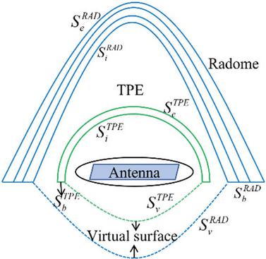
Figure 1 Schematic diagram of a typical RTA structure.
According to the equivalence principle, the selection of the shape and position of the virtual surface can be arbitrary, so we placed it completely outside the radome-covered space. For typical RTA structures, the ground plane (also a part of the antenna region) of the antennas usually seals the bottoms of TPE and radome, so the field intensities on the virtual surface are much weaker, compared to those in the interior region. Therefore, we assume that the field distributions on do not vary drastically as the materials of TPE change, i.e.
| (4) |
If we replace (2)–(4) into (1), an approximate representation of the radiating EM fields () from the combination of the antenna and TPE regions can be obtained
| (5) |
where and and are transmitted EM fields through the realistic and vacuum TPE, respectively.
To calculate the radiation from the entire RTA, we (Z)nsider the combination of antennas and TPE as a new antenna structure. By enclosing the radome through a virtual surface (blue dash line in Fig. 1) and utilizing the equivalence principle again with the assumption similar to (3), i.e. the EM fields on the virtual surface remain approximately unchanged with the radomes material, the radiating EM fields () outside the RTA (blue solid/dash lines in Fig. 1) can be calculated in the similar way as those in (1)–(5)
| (6) |
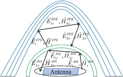
Figure 2 Field interactions among the antennas, TPE, and radome.
where and are the partial EM fields produced by the equivalent EM currents on the surfaces of the realistic and auxiliary vacuum radome, respectively. If we substitute (5) into (6), we obtain
| (7) |
Equation (7) represents a new approximate equivalence model for acquiring the EM radiation of the entire RTA structure.
2.2 Implementation details of the proposed approach and overcoming drawbacks
As shown in Fig. 2, the EM fields () radiating from the antenna region (including the antenna array and the ground plane) are accurately computed by the full-wave VSIE solver [23], incident on the TPE and then partly reflected multiple times to produce the reflection fields Another part of goes through the TPE to form the transmitted fields (), and these waves impinge upon the radome, giving rise to the fields transmitted into free space and the internal multi-reflected fields within the radome. These reflected fields, in part, transmit back through the TPE and subsequently generate higher-order reflection inside the space enclosed by TPE. In turn, the reflected fields from TPE act on the antenna region and alter the EM currents on them. Ultimately, the modified EM currents update the radiating fields () from antenna region. The above process will be repeated until the current distributions on the antenna region reach final (g) uilibrium. In general, the following inequality is used to quantitatively measure if the iterative process terminates
| (8) |
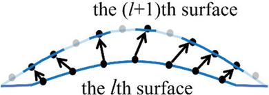
Figure 3 Locally planar approximation used in transmission matrix computation.
where is the coefficient vector of EM currents on the antenna region during the th iteration of the MLFMA, is the preset threshold, and means the 2-norm of a vector.
The above reflection and transmission fields are computed by using the locally planar approximation, ray tracing, and transmission matrix method as employed in the previously proposed VSIE-MSIMLFMA method [23] and in other high-frequency approaches [20, 21, 22, 24, 25]. In implementation, each curved surface of the TPE and the radome is discretized into triangular meshes, and the number of triangles on the outer ()th surface is always greater than that on the inner th surface. Consequently, during the raytracing process, the incident points on the th surface can always find the exit points on the ()th surface. However, a portion of triangles on the ()th surface invariably lack corresponding exit points (gray points in Fig. 3) corresponding to the incident points (black points in Fig. 3) on the th surface, resulting in null EM fields on those triangles. This causes the outer ()th surface be in a “broken state” as illustrated in Fig. 3. When the gap between the th and th surfaces is small relative to the wavelength, as in typical multilayer radomes without a TPE, the number of unmatched points is negligible, rendering the “broken state” insignificant. However, in RTA structures, the large air gap (relative to wavelength) between the TPE and the radome leads to failure in identifying exit points for numerous triangles on the outer surfaces. This renders accurate EM field computation impossible (necessitating zero-field approximation), substantially compromising the algorithm’s accuracy. Therefore, for a RTA system, the radome, the TPE, and the air gap between them cannot be treated as a single multilayer dielectric in the previous VSIE-MSI-MLFMA model. In contrast, the new mathematical model, derived in the preceding subsection, successfully decouples the TPE and radome into distinct regions, overcoming the difficulty in computing transmission matrices for RTAs inherent in the previous method.
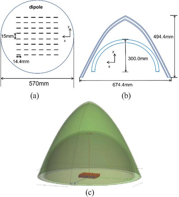
Figure 4 Radome-enclosed dipole array with a hemispherical TPE: (a) layout of the dipole array, (b) sideview of the radome and TPE, and (c) 3-D view of the entire RTA structure.
Table 1 Material and geometrical parameters of the radome and TPE
| Layer | min/max | ||
| thickness (mm) | |||
| Outer skin | 3.8 | 0.03 | 1.2/2.4 |
| Core | 1.5 | 0.015 | 4.8/9.6 |
| Inner skin | 3.8 | 0.03 | 1.2/2.4 |
| TPE | 1.3 | 0.003 | 15 |
3 NUMERICAL RESULTS
Numerical examples are presented in this section to validate the proposed method. All computations are performed on a workstation with a 2.4 GHz 16-core CPU and 384 GB RAM. Unless otherwise specified, the operating frequency is 10 GHz .
3.1 Radiation of a dipole antenna arrayhemispherical TPE-A-type sandwiched radome structure
The configuration of a dipole array enclosed by a hemispherical TPE and an A-type sandwiched radome is shown in Fig. 4. Each half-wave dipole element has a length of 14.4 mm and the spacing between two adjacent elements is 15 mm. The array is positioned 7.5 mm above a PEC ground plane with a diameter of 570 mm that almost seals the bottom of the TPE. The radome and TPE have the overall dimensions of and , respectively, and the material properties and thicknesses of the radome and TPE are listed in Table 1.
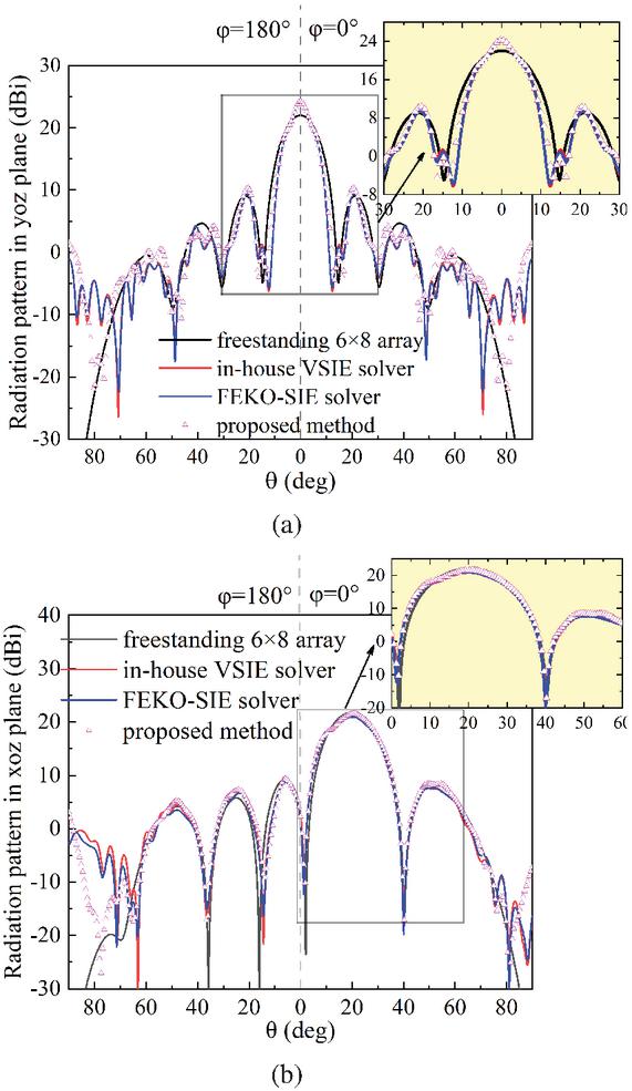
Figure 5 Radiation patterns of the RTA structure shown in Fig. 4 in (a) yoz-plane (scanning angle is ) and (b) xozplane (scanning angle is ).
Figures 5 (a) and (b) show the radiation patterns of the RTA in the and planes when the main beam scans to and , respectively. The proposed method, an in-house full-wave VSIE solver [3], and the commercial FEKO surface integral equation (SIE) solver [26] are applied to calculate the RTA’s radiation patterns for comparison purpose. Radiation distortion of the array caused by the radome and TPE is clearly observed in Figs. 5 (a) and (b), and the results of the proposed method agree well with the full-wave ones in the regions of main beam and nearby sidelobes (up to 60∘) as the scanning angle changes. The accuracy of the proposed method is reduced near the horizontal plane (), which may be caused by the approximation used in (4). Table 2 presents the computational time and memory usage of the methods, compared with the two full-wave solvers, the proposed hybrid method reduces the computational time from 19,000 s to 250 s and the memory cost by more than 95%.
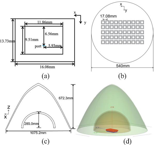
Figure 6 Radome-enclosed microstrip antenna array with a TPE: (a) sizes of the antenna element, (b) layout of the antenna array, (c) side view of the radome and TPE, and (d) 3-D view of the entire RTA.
Table 2 Comparison of time and memory usage of different methods
| Methods | No of | No of | Time | Mem | |
| Triangles | Tetrahedrons | (s) | (GB) | ||
| 1 | VSIE solver | 73,169 | 3,507,620 | 18,972 | 251.9 |
| FEKOSIE | 617,080 | – | 19,413 | 240.6 | |
| Proposed | 1,797,246 | – | 250 | 3.1 | |
| 2 | in [23] | 1,286,758 | 11,365 | 223 | 2.8 |
| VSIE solver | 68,880 | 3,915,121 | 85,824 | 213.3 | |
| Proposed | 1,286,758 | 11,365 | 389 | 5.1 |
3.2 Radiation of a microstrip antenna arrayhemispherical TPE single-layer radome
The second example is the computation of EM radiation of a microstrip array (MSA) enclosed by a single-layer radome and a TPE. The geometry of the antenna element and the layout of the antenna array are shown in Fig. 6. The relative permittivity of the substrate used in the MSA is , and the thickness and relative permittivity of the TPE are 15 mm and , respectively. The relative permittivity of the radome is , and the thickness varies from 12.3 mm at the top to 6.6 mm at the base.
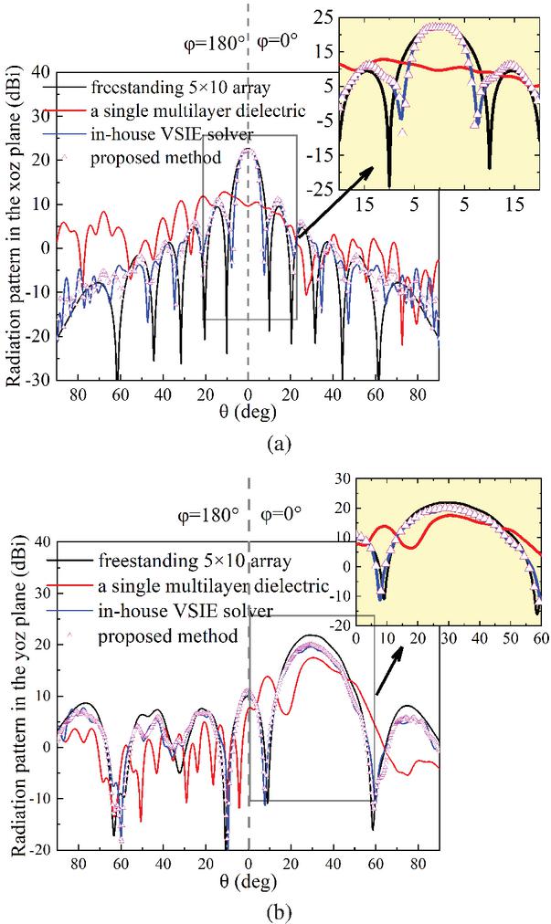
Figure 7 Radiation pattern of the RTA structure shown in Fig. 6 in (a) plane (scanning angle is ) and (b) plane (scanning angle is ).
Figure 7 shows the RTA’s radiation patterns calculated by the full-wave VSIE solver and the proposed method. Compared to the freestanding array’s radiation pattern, the major effects of the radome and TPE are gain reduction and increased ripples in the sidelobe regions. For two different scanning angles, the results of the proposed method match the full-wave solution in almost the entire upper half-space. Figure 7 also includes results (red lines) obtained by directly treating the TPE, air gap, and radome as a single multilayer dielectric and applying the method from [23]. As expected, these results significantly deviate from the full-wave solutions. This not only reveals the inherent limitations of the original method in analyzing RTAs but also demonstrates the effectiveness of the new approach. Table 2 confirms that the new method demands significantly less time and memory compared to the full-wave solver.
4 CONCLUSION
In this paper, a fast and efficient method is proposed for EM analysis of the RTA structures. By applying the approximate equivalence principle twice, a new mathematical model is derived. This model separates the TPE and radome into distinct regions, overcoming the fundamental difficulty in the existing VSIE-MSI-MLFMA method when handling the large air gap between the TPE and radome. The hybrid method takes into account the mutual coupling among the antennas, TPE, and radome in an iterative manner, and all interactions among the three regions can be efficiently computed by virtue of the MLFMA. Numerical results demonstrate the method’s good accuracy and significant reductions in computational time and memory requirements compared to full-wave solvers.
ACKNOWLEDGMENT
The authors wish to acknowledge the support of the National Natural Science Foundation of China under Grant 62171026 and the Aeronautical Science Foundation of China under Grant 20220026072001.
REFERENCES
[1] R. Shavit, Radome Electromagnetic Theory and Design. Oxford: John Wiley & Sons, 2018.
[2] A. Algaba-Brazález, P. Castillo-Tapia, M. C. Viganó, and O. Quevedo-Teruel, “Lenses combined with array antennas for the next generation of terrestrial and satellite communication systems,” IEEE Communications Magazine, vol. 62, no. 9, pp. 176–182, Sep. 2024.
[3] M. He, Q. Chen, Q. Yuan, K. Sawaya, and X. W. Xu, “A simple strip model in the volume-surface integral equation for analysis of arbitrary probe-fed conformal microstrip antennas,” IEEE Antennas Wireless Propag. Lett., vol. 8, pp. 530–533, 2009.
[4] P. Y. Zhou, Z. Zhang, and M. He, “Radiation pattern recovery of the impaired-radome-enclosed antenna array,” IEEE Antennas Wireless Propag. Lett., vol. 19, no. 9, pp. 1639–1643, Sep. 2020.
[5] A. Sadigh and E. Arvas, “Deformation of the horizontal radiation pattern of TV transmitting antennas due to a thin dielectric radome,” IEEE Trans. Antennas Propag., vol. 40, pp. 942–948, Aug. 1992.
[6] R. K. Gordon and R. Mittra, “Finite element analysis of axisymmetric radomes,” IEEE Trans. Antennas Propag., vol. 41, no. 7, pp. 975–980, July 1993.
[7] C. C. Lu and W. C. Chew, “A coupled surface-volume integral equation approach for the calculation of electromagnetic scattering from composite metallic and material targets,” IEEE Trans. Antennas Propag., vol. 48, no. 12, pp. 1866–1868, Dec. 2000.
[8] W. H. Yu, D. Arakaki, and R. Mittra, “On the solution of a class of large body problems with full or partial circular symmetry by using the finite-difference time-domain (FDTD) method,” IEEE Trans. Antennas Propag., vol. 48, no. 12, pp. 1810–1817, Dec. 2000.
[9] W. C. Chew, J. M. Jin, E. Michielssen, and J. M. Song, Fast and Efficient Algorithms in Computational Electromagnetics. Norwood, MA: Artech House, 2001.
[10] W. J. Zhao, L. W. Li, and Y. B. Gan, “Efficient analysis of antenna radiation in the presence of airborne dielectric radomes of arbitrary shape,” IEEE Trans. Antennas Propag., vol. 53, pp. 442–449, Jan. 2005.
[11] J. L. Guo, J. Y. Li, and Q. Z. Liu, “Analysis of arbitrarily shaped dielectric radomes using adaptive integral method based on volume integral equation,” IEEE Trans. Antennas Propag., vol. 54, no. 7, pp. 1910–1916, July 2006.
[12] M. He, X. W. Xu, B. Hu, and Y. Zheng, “Accurate analysis of arbitrarily shaped wire antenna-dielectric radome structures,” IEEE Antennas Wireless Propag. Lett., vol. 6, pp. 408–410, 2007.
[13] D. T. Paris, “Computer-aided radome analysis,” IEEE Trans. Antennas Propag., vol. 18, no. 1, pp. 7–15, Jan. 1970.
[14] J. L. Volakis and J. A. Shifflett, “CADDRAD: A physical optics radar/radome analysis code for arbitrary 3D geometries,” IEEE Antennas Propag. Mag., vol. 39, no. 6, pp. 73–79, Dec. 1997.
[15] T. Schuster and M. S. Cassidian, “Reach/preach-a physical optics-based tool for simulation of radome effects on antenna patterns,” in Proc. 6th Eur. Conf. on Antennas and Propag., pp. 3225–3229, 2011.
[16] M. A. Abdel Moneum, Z. Shen, J. L. Volakis, and O. Graham, “Hybrid po-mom analysis of large axisymmetric radomes,” IEEE Trans. Antennas Propag., vol. 49, no. 12, pp. 1657–1666, Dec. 2001.
[17] X. C. Nie, Y. B. Gan, N. Yuan, C. F. Wang, and L. W. Li, “An efficient hybrid method for analysis of slot arrays enclosed by a large radome,” J. Electromagn. Waves Appl., vol. 20, no. 2, pp. 249–264, Jan. 2006.
[18] H. F. Meng and W. B. Dou, “A hybrid method for the analysis of radome-enclosed horn antenna,” Prog. Electromagn. Res., vol. 90, pp. 219–233, 2009.
[19] Y. An and R. Chen, “A fast hybrid method for EM analysis of electrically large metal space frame radomes,” IEEE Antennas Wireless Propag. Lett., vol. 13, pp. 1124–1127, 2014.
[20] Z. Tan, M. Bai, X. Dang, and Y. Wu, “A hybrid method for wave propagation through large dielectric radome,” IEEE Antennas Wireless Propag. Lett., vol. 23, no. 10, pp. 3277–3281, Oct. 2024.
[21] M. Poveda-Garcia, F. Mesa, A. Algaba-Brazález, O. Quevedo-Teruel, and J. L. Gomez-Tornero, “Ray-tracing and physical optics modeling of leaky-wave antennas combined with lenses,” IEEE Trans. Antennas Propag., vol. 73, no. 3, pp. 1296–1307, Mar. 2025.
[22] Y. Youn, J. Choi, D. Kim, A. A. Omar, J. Choi, S. Chang, I. Yoon, S.-T. Ko, J. Lee, Y. Lee, M. O. Akinsolu, B. Liu, and W. Hong, “Dome-shaped mm-wave lens antenna optimization for wide-angle scanning and scan loss mitigation using geometric optics and multiple scattering,” IEEE J. Multiscale Multiphysics Comput. Tech., vol. 7, pp. 142–150, 2022.
[23] H. W. Ke, P. Y. Wang, J. B. Liu, J. Li, and M. He, “A hybrid method for fast and efficient evaluation of electromagnetic performance of the radome-enclosed antennas,” IEEE Trans. Antennas Propag., vol. 70, no. 10, pp. 9795–9805, Oct. 2022.
[24] M. Pubill-Font, F. Mesa, A. Algaba-Brazález, S. Clendinning, M. Johansson, and O. Quevedo-Teruel, “2-D ray-tracing model for multilayer dielectric dome arrays with inner reflections,” IEEE Open Journal of Antennas and Propagation, vol. 5, no. 4, pp. 845–854, Aug. 2024.
[25] J. H. Kim, H. J. Chun, I. P. Hong, Y. J. Kim, and Y. B. Park, “Analysis of FSS radomes based on physical optics method and ray tracing technique,” IEEE Antennas Wireless Propag. Lett., vol. 13, pp. 868–871, 2014.
[26] FEKO, Altair, Troy, MI, USA, 2021 [Online]. Available: www.altair.com/feko.
BIOGRAPHIES

Jintong Liu received the B.S. degree in electronic information engineering from Beijing Institute of Technology, Beijing, China, in 2023, where he is currently pursuing the Ph.D. degree. His current research interests include antenna-radome system analysis, periodic structure unit analysis, and computational electromagnetics.

Pengyuan Wang received the B.S. degree in communication engineering from North China Electric Power University, Baoding, China, in 2019, and the Ph.D. degree from the Beijing Institute of Technology, Beijing, China, in 2025. Since 2025, she has been with the Beijing Institute of Astronautical Systems Engineering, Beijing. Her current research interests include computational electromagnetics and EMC design.

Weidong Hu was born in Shanxi, China, in 1975. He received the B.S. degree in electronic engineering and the Ph.D. degree in electromagnetic field and microwave from Beijing Institute of Technology, Beijing, China, in 1997 and 2004, respectively. From 2004 to 2010, he was a Lecturer with the Microwave Laboratory, Beijing Institute of Technology. In 2011, he was a Visiting Scholar with the Electronic Engineering Department, City University of Hong Kong. Since 2022, he has been a Professor with the Beijing Key Laboratory of Millimeter Wave and Terahertz Technology, Beijing Institute of Technology. Since 2024, he has been the Chair of Terahertz Science Application Center in Zhuhai. His research interests include radar cross section measurements, microwave remote sensing, terahertz imaging, and antennas.

Mang He received the B.S. and Ph.D. degrees from the Department of Electrical Engineering, Beijing Institute of Technology, Beijing, China, in 1998 and 2003, respectively. He is currently a Full Professor with Beijing Institute of Technology. From 2003 to 2004, he was a Research Associate with the Department of Electronic Engineering, City University of Hong Kong, Hong Kong. From 2008 to 2009, he was a Post-Doctoral Research Fellow with the Department of Electrical and Communication Engineering, Tohoku University, Sendai, Japan. His current research interests include computational electromagnetics and its applications, antenna theory and design, and radome-antenna system analysis and design.
ACES JOURNAL, Vol. 41, No. 5, 406–412
DOI: 10.13052/2026.ACES.J.410503
© 2026 River Publishers